
OMRON D40A / G9SX-NSSafety Components/ Safety Door Switches/Non-Contact Door Switches
OMRON D40A / G9SX-NS Safety Components
- D40A / G9SX-NS Compact Non-Contact Door Switch/Non-Contact Door Switch Controller/Catalog
- D40A / G9SX-NS Compact Non-Contact Door Switch/Non-Contact Door Switch Controller/Dimensions
- D40A / G9SX-NS Compact Non-Contact Door Switch/Non-Contact Door Switch Controller/Lineup
- D40A / G9SX-NS Compact Non-Contact Door Switch/Non-Contact Door Switch Controller/Specifications
- Purchase the OMRON D40A / G9SX-NS Non-Contact Door Switches
OMRON D40A / G9SX-NS Dimensions
/Images/l_1832-25-118645-198x198.jpglast update: January 6, 2014

Solves Conventional Switch Issues to Provide Stable Detection
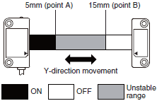
[Issue 1] The Switch does not accurately detect the door when it is closed slowly, resulting in an error.

[Solution 1] Conventional Switches

[Issue 2] It is nearly impossible to tell which door is open in a multi-door application.

[Solution 2]

With the D40A...
The auxiliary outputs can be used to easily indicate which door is open.
And with two-color indicators, mounting adjustments are also easy.
The D40A is the first Non-contact Door Switch to combine 2-color indicators, auxiliary outputs, and 30-switch connection capacity, allowing you to create a better safety environment.
[Issue 3] Various cable lengths and complex wiring are required for multiple doors.
[Solution 3]

The model with a connector allows you to select the cable lengths that are connected and purchase the cables of required lengths. Switches can be integrated into a single Switch with a connector.
Downtime can be reduced by replacing the cable and switch partially at maintenance time.
Two Types of Controller to Solve Productivity, Expandability, and Maintenance Issues
The G9SX-NS and G9SX-NSA are designed specifically for use with Non-contact door switch, and with the G9SX-NSA you can also connect mechanical safety door switches. Among other features, these Controllers support logical AND connections that enable partial stops. These Controllers make the most of D40A Switches.


Reduce Costs with these New-Concept Controllers
[Issue 1] Two Controllers are required for emergency stop switches and non-contact door switches.

[Issue 2] Another Controller has to be added to use an OFF-delay timer.

* Always use a manual reset when using an emergency stop.
last update: January 6, 2014
Purchase the OMRON Non-Contact Door Switches Please fill in the following
If you have just landed here, this product OMRON D40A / G9SX-NS Safety Components,Safety Components is offered online by Tianin FLD Technical Co.,Ltd. This is an online store providing Safety Components at wholesale prices for consumers. You can call us or send enquiry, we would give you the prices, packing,deliverty and more detailed information on the D40A / G9SX-NS We cooperate with DHL,TNT,FEDEX,UPS,EMS,etc.They guarantee to meet your needs in terms of time and money,even if you need your OMRON D40A / G9SX-NSSafety Components tomorrow morning (aka overnight or next day air) on your desk, 2, 3 days or more.Note to international customers, YES, we ship worldwide.
E8FC IoT Flow Sensors/Features
E2J Long Sensing-distance Capacitive Separate Amplifier Proximity Sensor/Features
A3P (Super Luminosity Type) Lighted Pushbutton Switch (Square) Ultra Bright LED Type/Features
G3J Simple Solid State Contactors/Features
E52 (For Packing Machine) Temperature Sensors for Packaging Machines/Features
OMRON D40A / G9SX-NS catalog
D40A / G9SX-NS Compact Non-Contact Door Switch/Non-Contact Door Switch Controller/Catalog- Catalog
- Manual
- CAD
English
Global Edition
| Catalog Name | Catalog Number [size] | Last Update | |
|---|---|---|---|
| | C140-E1-02 [2993KB] | Nov 01, 201820181101 | D40A, G9SX-NS Data Sheet |
OMRON D40A / G9SX-NS dimension
D40A / G9SX-NS Compact Non-Contact Door Switch/Non-Contact Door Switch Controller/Dimensionslast update: December 18, 2017
(Unit: mm)
D40A
Non-contact Door Switch (Switch/Actuator)
D40A-1C2
D40A-1C5
D40A-1C015-F
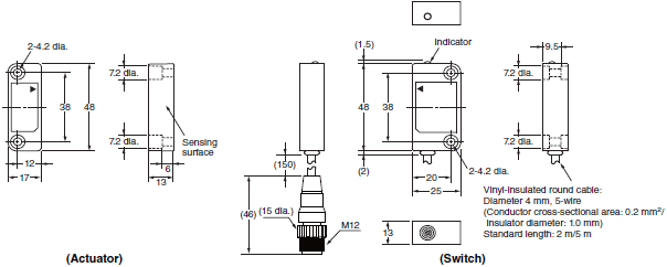
Accessories (Sold separately)
Socket on One Cable End (5-pole Connectors)
XS2F-D521-DG0-A (L=2m)
XS2F-D521-GG0-A (L=5m)
XS2F-D521-JG0-A (L=10m)
XS2F-D521-KG0-A (L=15m)
XS2F-D521-LG0-A (L=20m)

Sockets and Plugs on Cable Ends (5-pole Connectors)
XS2W-D521-DG1-A (L=2m)
XS2W-D521-GG1-A (L=5m)
XS2W-D521-JG1-A (L=10m)
XS2W-D521-KG1-A (L=15m)
XS2W-D521-LG1-A (L=20m)

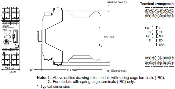
G9SX-NS
Non-contact Door Switch Controller
G9SX-NS202-[]
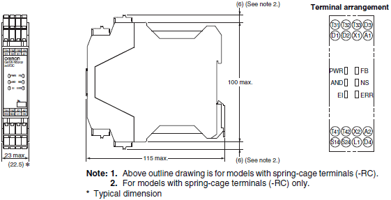
G9SX-NSA222-T03-[]
Expansion Unit
G9SX-EX401-[]
Expansion Unit (OFF-delayed Model)
G9SX-EX041-T-[]
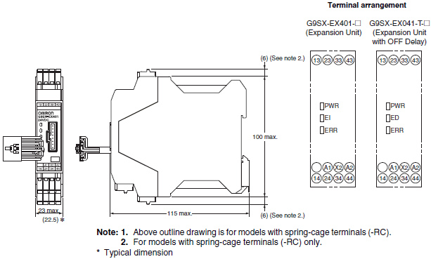
last update: December 18, 2017
OMRON D40A / G9SX-NS lineup
D40A / G9SX-NS Compact Non-Contact Door Switch/Non-Contact Door Switch Controller/Lineuplast update: December 18, 2017
D40A
Non-Contact Door Switches (Switch/Actuator)
| Classification | Appearance | Auxiliary outputs | Cable length | Model |
|---|---|---|---|---|
| Standard models |  | Semiconductor outputs *1 | 2 m | D40A-1C2 |
| 5 m | D40A-1C5 | |||
| Connector model |  | 0.15 m | D40A-1C015-F *2 |
Note: The Switch must be used in combination with a Non-Contact Door Switch Controller (G9SX-NS[]) or Safety
Controller (G9SP).
*1. PNP open-collector semiconductor output.
*2. The model with a connector is not KOSHA certified.
Cable with connector
| Connector Type | Cable Length | Model | Packing Unit |
|---|---|---|---|
| Single-end | 2 m | XS2F-D521-DG0-A | 5 |
| 5 m | XS2F-D521-GG0-A | 5 | |
| 10 m | XS2F-D521-JG0-A | 1 | |
| 15 m | XS2F-D521-KG0-A | 1 | |
| 20 m | XS2F-D521-LG0-A | 1 | |
| Double-end | 2 m | XS2W-D521-DG1-A | 5 |
| 5 m | XS2W-D521-GG1-A | 5 | |
| 10 m | XS2W-D521-JG1-A | 1 | |
| 15 m | XS2W-D521-KG1-A | 1 | |
| 20 m | XS2W-D521-LG1-A | 1 |
Controllers
Non-Contact Door Switch Controllers G9SX-NS[]
| Safety outputs *1 | Auxiliary outputs *3 | Logical AND con- nection input | Logical AND con- nection output | Max. OFF delay time *4 | Rated voltage | Terminal block type | Model | |
|---|---|---|---|---|---|---|---|---|
| Instant- aneous | OFF- delayed *2 | |||||||
| 2 (Semi- conductors) | 0 | 2 (Semi- conductors) | 1 | 1 | --- | 24 VDC | Screw terminals | G9SX-NS202-RT |
| Spring- cage terminals | G9SX-NS202-RC | |||||||
| 2 (Semi- conductors) | 3.0 s | Screw terminals | G9SX-NSA222-T03-RT | |||||
| Spring- cage terminals | G9SX-NSA222-T03-RC | |||||||
Note: For details, refer to Data Sheet or subsequent pages.
*1. P channel MOS FET transistor output
*2. The OFF-delayed output becomes an instantaneous output by setting the OFF-delay time to 0 s.
*3. PNP transistor output
*4. The OFF-delay time can be set in 16 steps as follows:
0/0.2/0.3/0.4/0.5/0.6/0.7/0.8/0.9/1.0/1.2/1.4/1.8/2.0/2.5/3.0 s
Safety Controller G9SP Series
| Name | No. of I/O points | Unit version | Model | |||
|---|---|---|---|---|---|---|
| Safety inputs | Test outputs | Safety outputs | Standard outputs | |||
| Safety Controller | 10 | 4 | Semiconductor outputs: 4 | 4 | Ver.2.0 | G9SP-N10S |
| 10 | 6 | Semiconductor outputs: 16 | -- | G9SP-N10D | ||
| 20 | 6 | Semiconductor outputs: 8 | -- | G9SP-N20S | ||
Note: For details, refer to the G9SP Series Catalog (Catalog No. F090).
G9SX-NS
Non-Contact Door Switch Controllers
| Safety outputs *1 | Auxiliary outputs *3 | Logical AND con- nection input | Logical AND con- nection output | Max. OFF delay time *4 | Rated voltage | Terminal block type | Model | |
|---|---|---|---|---|---|---|---|---|
| Instant- aneous | OFF- delayed *2 | |||||||
| 2 (Semi- conductors) | 0 | 2 (Semi- conductors) | 1 | 1 | --- | 24 VDC | Screw terminals | G9SX-NS202-RT |
| Spring- cage terminals | G9SX-NS202-RC | |||||||
| 2 (Semi- conductors) | 3.0 s | Screw terminals | G9SX-NSA222-T03-RT | |||||
| Spring- cage terminals | G9SX-NSA222-T03-RC | |||||||
*1. P channel MOS FET transistor output
*2. The OFF-delayed output becomes an instantaneous output by setting the OFF-delay time to 0 s.
*3. PNP transistor output
*4. The OFF-delay time can be set in 16 steps as follows:
0/0.2/0.3/0.4/0.5/0.6/0.7/0.8/0.9/1.0/1.2/1.4/1.8/2.0/2.5/3.0 s
Expansion Units
| Safety outputs | Auxiliary outputs | OFF-delay time | Rated voltage | Terminal block type | Model | |
|---|---|---|---|---|---|---|
| Instantaneous | OFF-delayed | |||||
| 4PST-NO | --- | 1 (Semi- conductor) *1 | --- | 24 VDC | Screw terminals | G9SX-EX401-RT |
| Spring-cage terminals | G9SX-EX401-RC | |||||
| --- | 4PST-NO | *2 | Screw terminals | G9SX-EX041-T-RT | ||
| Spring-cage terminals | G9SX-EX041-T-RC | |||||
*1. PNP transistor output
*2. The OFF-delay time is synchronized to the OFF-delay time setting in the connected Controller (G9SX-NSA222-T03-[]).
Accessories
Terminal Block
| Appearance * | Specifications | Applicable units | Model | Remarks |
|---|---|---|---|---|
 | Terminal Block with screw terminals (3-pin) | G9SX-NSA | Y9S-03T1B-02A | Two Terminal Blocks (black) with screw terminals, and a set of six code marks to prevent erroneous insertion. |
| Terminal Block with screw terminals (4-pin) | G9SX-NS G9SX-EX-[] | Y9S-04T1B-02A | Two Terminal Blocks (black) with screw terminals, and a set of six code marks to prevent erroneous insertion. | |
 | Terminal Block with spring-cage terminals (3-pin) | G9SX-NSA | Y9S-03C1B-02A | Two Terminal Blocks (black) with spring-cage terminals, and a set of six code marks to prevent erroneous insertion. |
| Terminal Block with spring-cage terminals (4-pin) | G9SX-NS G9SX-EX-[] | Y9S-04C1B-02A | Two Terminal Blocks (black) with spring-cage terminals, and a set of six code marks to prevent erroneous insertion. |
Note: The G9SX main unit comes with a terminal block as standard equipment. The accessories shown here can be
ordered as a replacement.
* The illustrations show 3-pin types
last update: December 18, 2017
OMRON D40A / G9SX-NS specification
D40A / G9SX-NS Compact Non-Contact Door Switch/Non-Contact Door Switch Controller/Specificationslast update: December 18, 2017
D40A
Non-contact Door Switches
Ratings and Characteristics
| Model | D40A-1C[] | |
|---|---|---|
| Interlock type | Type 4 (EN ISO 14119) | |
| Coding level | Low level coded (EN ISO 14119) | |
| Operating characteristics *2 | Operating distance OFF→ON | 5 mm min. *1 |
| Operating distance ON→OFF | 15 mm max. *1 | |
| Differential travel | 20% or less of operating distance at 23°C (maximum 2.5 mm) | |
| Influence of temperature (max.) | ±20% of operating distance at 23°C, within temperature range of -10 to 55°C | |
| Repeat accuracy | ±10% or less of operating distance at 23°C | |
| Ambient operating temperature | -10 to 55°C (no icing or condensation) | |
| Ambient operating humidity | 25% to 85% | |
| Insulation resistance (between charged parts and case) | 50 MΩ max. (at 500 VDC) | |
| Dielectric strength (between charged parts and case) | 1,000 VAC for 1 min | |
| Pollution degree | 3 | |
| Electromagnetic compatibility | IEC/EN 60497-5-3 compliant | |
| Vibration resistance | 10 to 55 to 10 Hz (single amplitude: 0.75 mm, double amplitude: 1.5 mm) | |
| Shock resistance | 300 m/s2 min. | |
| Degree of protection | IP67 | |
| Material | PBT resin | |
| Mounting method | M4 screws | |
| Terminal screw tightening torque | 1 N·m | |
| Power supply voltage | 24 VDC +10%/-15% | |
| Power consumption | 0.6 W max. | |
| Auxiliary outputs *3 | 24 VDC, 10 mA (PNP open-collector outputs) | |
| LED indicators | Actuator not detected (red); actuator detected (yellow) | |
| Connection cables | 2 m, 5 m, 0.15m (Connector type) | |
| Number of connectable switches | 30 max. (wiring length: 100 m max.) *4 | |
| Weight | Switch: approx. 145 g, actuator: approx. 20 g (D40A-1C2) | |
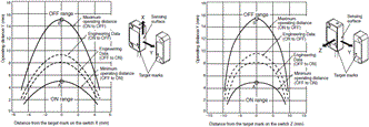
*1. The condition of this distance are that the switch and actuator target marks are on the same axis and the sensing
surfaces are exactly parallel condition. OFF to ON distance shows the switch approaching (Point A in the engineering
data graph) and ON to OFF distance shows the switch separating away (Point B in the engineering data graph).
*2. For details on response time and operating time, refer to the catalog or manual of a safety controller to be connected.
*3. Turns ON when the actuator is approaching. The G3R series of the SSR can be driven at an auxiliary output of 10 mA.
Contact your OMRON representative for details.
*4. For details, refer to item 5 on Data sheet.
Engineering Data
Note: 1. The operating distance is the distance between the switch and actuator sensing surfaces.
2. The graph indicates shifting to X or Z direction from following condition that the switch and actuator target marks
are on the same axis and the sensing surfaces are exactly parallel condition.
Dashed lines indate reference value for maximum and minimun oprating distance at abient temperature +23°C.
The solid line indicates reference values of the maximum and minimum operating distances.
3. The operating distance may be affected by ambient metal, magnet catches, and temperature.
Cable with connector
Ratings and Characteristics
| Rated current | 4 A |
|---|---|
| Rated voltage | 250 VAC/VDC |
| Contact resistance (Connector) | 40 mΩ max. (20 mV max., 100 mA max.) |
| Insulation resistance | 1,000 MΩ min. (at 500 VDC) |
| Dielectric strength (Connector) | 1,500 VAC for 1 min (leakage current: 1 mA max.). |
| Degree of protection | IP67 (IEC60529) |
| Insertion tolerance | 200 times min. |
| Cable holding strength | Cable diameter: 6 mm 98 N/15 s |
| Ambient operating temperature range | Operating: - 25°C to 70°C |
| Ambient humidity range | 20% to 85% |
Materials and Finish
| Item | XS2F/H/W | |
|---|---|---|
| Contacts | Materials | Phosphor bronze |
| Finish | Nickel base, 0.4-μm gold plating | |
| Thread bracket | Materials | Brass |
| Finish | Nickel plated | |
| Pin block | Materials | PBT resin (UL94V-0) |
| Finish | For DC: light gray; for AC: dark gray | |
| O-ring/rubber bushing | Rubber | |
| Cover | PBT resin (UL94V-0) | |
G9SX-NS
Non-contact Door Switch Controllers
Ratings
Power input
| Model | G9SX-NS202-[] | G9SX-NSA222-T03-[] | G9SX-EX-[] |
|---|---|---|---|
| Rated supply voltage | 24 V DC | ||
| Operating voltage range | -15% to 10% of rated supply voltage | ||
| Rated power consumption * | 3 W max. | 4 W max. | 2 W max. |
* Power consumption of loads not included.
Inputs
| Model | G9SX-NS202-[]/G9SX-NSA222-T03-[] |
|---|---|
| Safety input *1 | Operating voltage: 20.4 VDC to 26.4 VDC, internal impedance: approx. 2.8 kΩ *2 |
| Feedback/reset input |
*1. Only applies to the G9SX-NSA222-T03-[]. Refers to input other than that from the Non-contact Door Switch.
*2. Provide a current equal to or higher than that of the minimum applicable load of the connected input control device.
Outputs
| Model | G9SX-NS202-[]/G9SX-NSA222-T03-[] |
|---|---|
| Instantaneous safety output *1 OFF-delayed safety output *1 | P channel MOS FET transistor output Load current: 0.8 A DC max. *2 |
| Auxiliary output | PNP transistor output Load current: 100 mA max. |
*1. While safety outputs are in the ON state, the following signal sequence is output continuously for diagnosis.
When using the safety outputs as input signals to control devices (i.e. Programmable Controllers), consider the OFF
pulse shown below.

*2. The following derating is required when Units are mounted side-by-side.
G9SX-NS202-[]/G9SX-NSA222-T03-[]: 0.4 A max. load current
Expansion Unit
| Model | G9SX-EX-[] |
|---|---|
| Rated load | 250 VAC, 3 A/30 VDC, 3 A (resistive load) |
| Rated carry current | 3 A |
| Maximum switching voltage | 250 VAC, 125 VDC |
Characteristics
| Model | G9SX-NS202-[] | G9SX-NSA222-T03-[] | G9SX-EX-[] | |
|---|---|---|---|---|
| Over-voltage category (IEC/EN 60664-1) | II | II (Relay outputs 13 to 43 and 14 to 44: III) | ||
| Operating time (OFF to ON state) *1 | Logical AND connection input: 100 ms max. D40A connected: 100 ms max. D40Z connected: 200 ms max. | Safety input: 50 ms max. *2 Logical AND connection input: 100 ms max. *3 D40A connected: 100 ms max. *3 D40Z connected: 200 ms max. *3 | 30 ms max. *4 | |
| Response time (ON to OFF state) *1 | 15 ms max. (Logical AND connection input: OFF) Logical AND connection input: 15 ms max. D40A connected: 20 ms max. *6 D40Z connected: 45 ms max. | 15 ms max. (Logical AND connection input: OFF) Safety input: 15 ms max. Logical AND connection input: 15 ms max. D40A connected: 20 ms max. *6 D40Z connected: 45 ms max. | 10 ms max. *4 | |
| ON-state residual voltage | 3.0 V max. (safety output, auxiliary output) | |||
| OFF-state leakage current | 0.1 mA max. (safety output, auxiliary output) | |||
| Maximum wiring length of safety input, logical AND connection input, and Non-contact Door Switch input | 100 m max. (External connection impedance: 100 Ω max. and 10 nF max.) | |||
| Reset input time (Reset button pressing time) | 100 ms min. | |||
| Accuracy of OFF-delay time *5 | --- | Within ±5% of the set value | Within ±5% of the set value | |
| Insulation resistance | Between logical AND connection terminals, and power supply input terminals and other input and output terminals connected together | 20 MΩ min. (at 100 VDC) | --- | |
| Between all terminals connected together and DIN rail | 100 MΩ min. (at 500 VDC) | |||
| Dielectric strength | Between logical AND connection terminals, and power supply input terminals and other input and output terminals connected together | 500 VAC for 1 min. | --- | |
| Between all terminals connected together and DIN rail | 1,200 VAC for 1 min | |||
| Between different poles of outputs | --- | |||
| Between relay outputs connected together and other terminals connected together | 2,200 VAC for 1 min | |||
| Vibration resistance | 10 to 55 to 10 Hz, 0.375 mm single amplitude (0.75 mm double amplitude) | |||
| Shock resistance | Destruction | 300 m/s2 | ||
| Malfunction | 100 m/s2 | |||
| Durability | Electrical | --- | 100,000 cycles min. rated load, switching frequency: 1,800 cycles/hour) | |
| Mechanical | --- | 5,000,000 cycles min. (switching frequency: 7,200 cycles/hour) | ||
| Ambient operating temperature | -10 to 55°C (no icing or condensation) | |||
| Ambient operating humidity | 25% to 85% | |||
| Terminal tightening torque | 0.5 N·m (For the G9SX-NS[]-RT (with screw terminals) only) | |||
| Weight | Approx. 125 g | Approx. 200 g | Approx. 165 g | |
*1. When two or more Units are connected by logical AND, the operating time and response time are the sum total of the
operating times and response times, respectively, of all the Units connected by logical AND.
The operating time/response time of the Non-contact Door Switch are included of the time with the D40A/D40Z.
*2. Represents the operating time when the safety input turns ON with all other conditions set.
*3. Represents the operating time when the logical AND input and the Non-contact Door Switch input turn ON with all
other conditions set.
*4. This does not include the operating time or response time of G9SX-NS[] that are connected.
*5. This does not include the operating time or response time of internal relays in the G9SX-EX-[].
*6. The failure detection time for 24 V short-circuit failure on the input to Non-contact Door Switches is 35 ms max.
If using the Switch for an application other than as a Door Switch, calculate the safe distance using a failure detection
time of 35 ms.
last update: December 18, 2017
- NO. D40A / G9SX-NS
- TYPE:Safety Door Switches Non-Contact Door Switches
 Copyright Statement
 - DATE:2021-06-12
- Associated products:
D40Z Compact non-contact Door Switch/Features NX-CSG / SL5 / SI / SO NX-series Communication Control Unit/Safety Control Units/Features