OMRON E5CSControl Components/ Temperature Controllers/General-purpose
OMRON E5CS Control Components
OMRON E5CS Dimensions
/Images/l_166-25-118773-198x198.jpglast update: December 19, 2013
• Easy setting using DIP switch.
• Models with two alarms added to Series, ideal for applications requiring alarms.
• Universal-input (thermocouple/platinum resistance thermometer) models also available.
• Clearly visible digital display with character height of 13.5 mm.
• RoHS compliant.
last update: December 19, 2013
Purchase the OMRON General-purpose Please fill in the following
If you have just landed here, this product OMRON E5CS Control Components,Control Components is offered online by Tianin FLD Technical Co.,Ltd. This is an online store providing Control Components at wholesale prices for consumers. You can call us or send enquiry, we would give you the prices, packing,deliverty and more detailed information on the E5CS We cooperate with DHL,TNT,FEDEX,UPS,EMS,etc.They guarantee to meet your needs in terms of time and money,even if you need your OMRON E5CSControl Components tomorrow morning (aka overnight or next day air) on your desk, 2, 3 days or more.Note to international customers, YES, we ship worldwide.
CS1W-CIF31 USB-Serial Conversion Cable/Features
E2K-X Cylindrical Proximity Sensor/Features
A3P (Super Luminosity Type) Lighted Pushbutton Switch (Square) Ultra Bright LED Type/Features
KM-N2-FLK Power Monitor/Features
K8DS-PU Three-phase Undervoltage and Phase-sequence Phase-loss Relay/Features
OMRON E5CS dimension
E5CS Temperature Controllers/Dimensionslast update: November 12, 2012
Controller
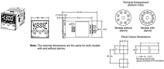
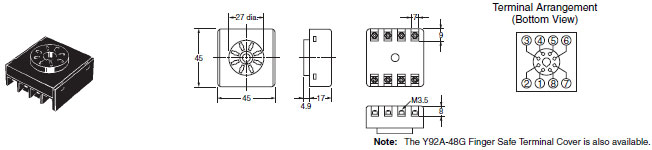
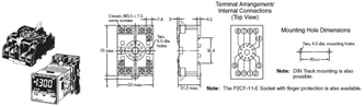
E5CS-U
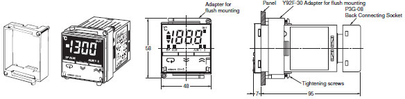
E5CS-U + Adapter for Flush Mounting (Enclosed) + Back Connecting Socket (Order Separately)
(Without Alarms)
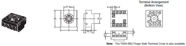
E5CS-U + Adapter for Flush Mounting (Enclosed) + Back Connecting Socket (Order Separately)
(Without Alarms)
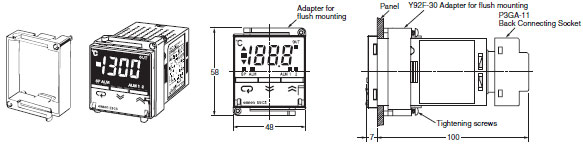
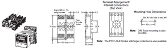
Note: Use the P2CF-08 and P3G-08 Sockets for models without alarms, and use the P2CF-11 and P3GA-11 Sockets for models with alarms.
Accessories (Order Separately)
8-pin Sockets without Alarms
P2CF-08 Front Connecting Socket
P3G-08 Back Connecting Socket
11-pin Sockets with Alarms
P2CF-11 Front Connecting Socket
P3GA-11 Back Connecting Socket
Note: Do not use any other types of Sockets. Doing so will adversely affect the accuracy.
Applicable Thermistors
Use Element Interchangeable Thermistors (E52-THE5A, E52-THE6D, and E52-THE6F) to connect to the E5CS-[]GU. For details on Sensors, refer to E52.
Hard Protective Cover
The Y92A-48B Hard Protective Cover is available for the following applications.
• To protect the set from dust and dirt.
• To prevent the panel from being accidentally touched causing displacement of set values.
• To provide effective protection against water droplets.
last update: November 12, 2012
OMRON E5CS catalog
E5CS Temperature Controllers/Catalog- Catalog
- Manual
- CAD
English
Global Edition
| Catalog Name | Catalog Number [size] | Last Update | |
|---|---|---|---|
| | - [1134KB] | Aug 04, 201520150804 | E5CS Data Sheet |
OMRON E5CS specification
E5CS Temperature Controllers/Specificationslast update: August 05, 2015
Ratings
| Supply voltage | 100 to 240 VAC, 50/60 Hz 24 VAC, 50/60 Hz; 24 VDC | |
|---|---|---|
| Operating voltage range | 85% to 110% of rated supply voltage | |
| Power consumption | 100 to 240 VAC: 5 VA 24 VAC: 3 VA, 24 VDC: 2 W | |
| Sensor input | Thermocouple: K, J, L Platinum resistance thermometer: Pt100, JPt100 Thermistor: E52-THE[][] Universal-input (thermocouple/platinum resistance thermometer): K, J, L, T, U, N, R, Pt100, JPt100 | |
| Control output | Relay output | SPDT, 250 VAC, 3 A (resistive load) |
| Voltage output (for driving the SSR) | 12 VDC, 21 mA (with short-circuit protection circuit) | |
| Control method | ON/OFF or 2-PID (with automatic PID parameter setting function) | |
| Alarm output | SPST-NO, 250 VAC, 1A (resistive load) | |
| Setting method | Digital setting using front panel keys | |
| Indication method | 7-segment digital display (character height: 13.5 mm) and deviation indicators | |
| Other functions | Setting change prohibit (key protection) Input shift Temperature unit change (°C/°F) Direct/reverse operation Temperature range, Sensor switching (K/J/L, Pt100/JPt100) Switching is performed between a thermocouple and platinum resistance thermometer for universal-input models. Control period switching 8-mode alarm output Sensor error detection (excluding thermistor models) | |
| Ambient operating temperature | -10 to 55°C (with no condensation or icing); with 3-year guarantee: -10 to 50°C | |
| Ambient operating humidity | 25% to 85% | |
| Storage temperature | -25 to 65°C (with no condensation or icing) | |
Note: Do not use an inverter output as the power supply. (Refer to Safety Precautions for All Temperature Controllers.)
Characteristics
| Setting accuracy | Thermocouple *1: (±1% of indication value or ±2°C, whichever is greater) ±1 digit max. Platinum resistance thermometer *2: (±0.5% of indication value or ±1°C, whichever is greater) ±1 digit max. Thermistor *3: (1% FS of indication value) ±1 digit max. | |
|---|---|---|
| Indication accuracy (ambient temperature of 23°C) | ||
| Influence of temperature | R thermocouple inputs: (±2% of PV or ±10°C, whichever is greater) ±1 digit max. Other thermocouple inputs: (±2% of PV or ±4°C, whichever is greater) ±1 digit max. Platinum resistance thermometer inputs: (±1% of PV or ±2°C, whichever is greater) ±1 digit max. Thermistor: (±2% FS) ±1 digit max. | |
| Influence of voltage | ||
| Influence of EMS. (at EN 61326-1) | ||
| Hysteresis (for ON/OFF control) | 0.2% FS (0.1% FS for universal-input (thermocouple/platinum resistance thermometer) models) | |
| Proportional band (P) | 1 to 999°C (automatic adjustment using auto-tuning/self-tuning) | |
| Integral time (I) | 1 to 1,999 s (automatic adjustment using auto-tuning/self-tuning) | |
| Derivative time (D) | 1 to 1,999 s (automatic adjustment using auto-tuning/self-tuning) | |
| Alarm output range | Absolute-value alarm: Same as the control range Other: 0 to input setting range full scale (°C or °F) Alarm hysteresis: 0.2°C or °F (fixed) | |
| Control period | 2/20 s | |
| Sampling period | 500 ms | |
| Insulation resistance | 20 MΩ min. (at 500 VDC) | |
| Dielectric strength | 2,000 VAC, 50/60 Hz for 1 min between current-carrying terminals of different polarity | |
| Vibration resistance | Malfunction | 10 to 55 Hz, 20 m/s2 for 10 min each in X, Y, and Z directions |
| Destruction | 10 to 55 Hz, 0.75-mm single amplitude for 2 hr each in X, Y, and Z directions | |
| Shock resistance | Malfunction | 100 m/s2 min., 3 times each in six directions |
| Destruction | 300 m/s2 min., 3 times each in six directions | |
| Life expectancy | Electrical | 100,000 operations min. (relay output models) |
| Weight | Approx. 110 g (Controller only) | |
| Degree of protection | Front panel: Equivalent to IP50, Enclosure Category 2 (IEC 60529), Rear case: IP20; Terminals: IP00 | |
| Memory protection | EEPROM (non-volatile memory) (number of writes: 1,000,000) | |
| EMC | EMI Radiated: EN 55011 Group 1 Class A EMI Conducted: EN 55011 Group 1 Class A Radiated Electromagnetic Field Immunity: EN 61000-4-2: 4 kV contact discharge (level 2), 8 kV air discharge (level 3) RF-interference Immunity: EN 61000-4-3: 10 V/m (80-1000 MHz, 1.4-2.0 GHz amplitude modulated) (level 3), 10 V/m (900 MHz pulse modulated) Conducted Disturbance Immunity: EN 61000-4-6: 3 V (0.15 to 80 MHz) (level 2) Noise Immunity (First Transient Burst Noise): EN 61000-4-4 Burst Immunity: 2 kV power-line (level 3), 1 kV I/O signal-line (level 3) Surge Immunity: EN 61000-4-5: Power line: Normal mode 1 kV; Common mode 2 kV, Output line (relay output): Normal mode 1 kV; Common mode 2 kV Voltage Dip/Interrupting Immunity: EN 61000-4-11 0.5 cycle, 100% (rated voltage) | |
| Approved standards | UL 61010-1 (listing) CSA C22.2 No.1010-1 | |
| Conformed standards | EN 61326-1 *4, EN 61010-1, IEC 61010-1 | |
*1. The following exceptions apply to thermocouples.
• U, L: ±2°C ±1 digit max.
• R: ±3°C ±1 digit max. at 200°C or less
*2. The following exception applies to platinum resistance thermometers.
• Input set values 1 for E5CS-U: 1% FS ±1 digit max.
*3. The following exceptions apply to thermistors.
• When the unit setting is °C, temperature indication ranges exceeding the set temperature range ±10% FS may not
be accurate.
• When the unit setting is °F, the temperature range for the input setting numbers 4 and 9 (609 to 630°F) and
temperature indication ranges exceeding the set temperature range −5% FS to +10% FS may not be accurate.
*4. Industrial electromagnetic environment (EN/IEC 61326-1 Table 2)
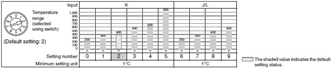
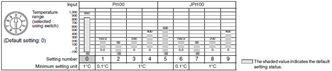
Temperature Range
Thermocouple Input Models
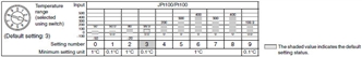
Platinum Resistance Thermometer Input Models
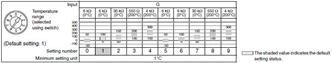
Thermistor Input Models
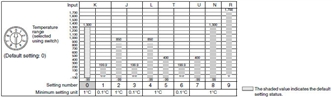
Universal-input (Thermocouple/Platinum Resistance Thermometer) Models
Using Thermocouple Sensors, Control Mode Switch 5: OFF
Using Platinum Resistance Thermometers, Control Mode Switch 5: ON
last update: August 05, 2015
OMRON E5CS lineup
E5CS Temperature Controllers/Lineuplast update: October 11, 2012
Case Color: Light Gray, Thermocouple or Platinum Resistance Thermometer, Power Supply Voltage: 100 to 240 VAC
| Size | Type | Control modes | Alarms | Outputs | Model with thermocouple | Model with platinum resistance thermometer |
|---|---|---|---|---|---|---|
| E5CS-U 48 × 48 mm | Plug-in | ON/OFF or PID | 0 | Relay | E5CS-RKJU-W | E5CS-RPU-W |
| Voltage (for driving SSR) | E5CS-QKJU-W | E5CS-QPU-W | ||||
| 1 | Relay | E5CS-R1KJU-W | E5CS-R1PU-W | |||
| Voltage (for driving SSR) | E5CS-Q1KJU-W | E5CS-Q1PU-W |
Case Color: Light Gray, Thermocouple or Platinum Resistance Thermometer, Power Supply Voltage: 24 VAC/VDC
| Size | Type | Control modes | Alarms | Outputs | Model with thermocouple | Model with platinum resistance thermometer |
|---|---|---|---|---|---|---|
| E5CS-U 48 × 48 mm | Plug-in | ON/OFF or PID | 0 | Relay | E5CS-RKJDU-W | E5CS-RPDU-W |
| Voltage (for driving SSR) | E5CS-QKJDU-W | --- | ||||
| 1 | Relay | E5CS-R1KJDU-W | E5CS-R1PDU-W | |||
| Voltage (for driving SSR) | E5CS-Q1KJDU-W | --- |
Case Color: Light Gray, Thermistor or Universal-input, Power Supply Voltage: 100 to 240 VAC
| Size | Type | Control modes | Alarms | Outputs | Model with thermistor | Model with universal-input (thermocouple and platinum resistance thermometer) |
|---|---|---|---|---|---|---|
| E5CS-U 48 × 48 mm | Plug-in | ON/OFF or PID | 0 | Relay | E5CS-RGU-W | E5CS-RTU-W |
| Voltage (for driving SSR) | E5CS-QGU-W | E5CS-QTU-W | ||||
| 1 | Relay | E5CS-R1GU-W | E5CS-R1TU-W | |||
| Voltage (for driving SSR) | E5CS-Q1GU-W | E5CS-Q1TU-W | ||||
| 2 * | Relay | --- | E5CS-R2TU-W | |||
| Voltage (for driving SSR) | E5CS-Q2TU-W |
* There is no alarm output 2 mode switch. The default setting for alarm output 2 is for the upper limit alarm mode. To
change the setting, change the alarm type for alarm output 2 in initial setting level 5. For details, refer to the "E5CSV/
E5CS-U Digital Temperature Controller User's Manual" (Cat. No. H140-E1).
Case Color: Light Gray, Thermistor, Power Supply Voltage: 24 VAC/VDC
| Size | Type | Control modes | Alarms | Outputs | Model with thermistor |
|---|---|---|---|---|---|
| E5CS-U 48 × 48 mm | Plug-in | ON/OFF or PID | 0 | Relay | E5CS-RGDU-W |
| 1 | E5CS-R1GDU-W |
Accessories (Order Separately)
Socket without Alarm (8 Pins)
| Type | Model |
|---|---|
| Front Connecting Socket | P2CF-08 |
| Back Connecting Socket (flush mounting) | P3G-08 |
| Front Connecting Socket (with finger protection) | P2CF-08-E |
| Finger Safe Terminal Cover for P3G | Y92A-48G |
Socket with Alarm (11 Pins)
| Type | Model |
|---|---|
| Front Connecting Socket | P2CF-11 |
| Back Connecting Socket (flush mounting) | P3GA-11 |
| Front Connecting Socket (with finger protection) | P2CF-11-E |
| Finger Safe Terminal Cover for P3G | Y92A-48G |
Protective Cover
| Type | Model |
|---|---|
| Hard Protective Cover | Y92A-48B |
last update: October 11, 2012
- NO. E5CS
- TYPE:Temperature Controllers General-purpose
 Copyright Statement
 - DATE:2021-06-09
- Associated products:
E5ER-T Programmable Digital Controller/Features E5GN Basic-type Digital Temperature Controller (48 x 24 mm)/Features