OMRON G9SX-GSSafety Components/ Safety Units / Safety Relay Units/G9SX-series Flexible Safety Units
OMRON G9SX-GS Safety Components
OMRON G9SX-GS Dimensions
/Images/l_1882-25-118888-198x198.jpglast update: January 10, 2013
• Two functions support two types of application:
• Auto switching: For applications where operators work together with machines
• Manual switching: For applications with limited operations
• External indicator outputs enable indicating the switching status of two safety input devices.
• Auxiliary outputs enable monitoring of safety inputs, safety outputs, and errors.
• Detailed LED indications enable easy diagnosis.
• Logical AND connection allows complicated applications in combination with other G9SX-series Units.
• Certification for compliance with IEC/EN 61508 (SIL3), IEC/EN 62061 (SIL3) and EN ISO13849-1 (PLe/Safety Category 4).
last update: January 10, 2013
Purchase the OMRON G9SX-series Flexible Safety Units Please fill in the following
If you have just landed here, this product OMRON G9SX-GS Safety Components,Safety Components is offered online by Tianin FLD Technical Co.,Ltd. This is an online store providing Safety Components at wholesale prices for consumers. You can call us or send enquiry, we would give you the prices, packing,deliverty and more detailed information on the G9SX-GS We cooperate with DHL,TNT,FEDEX,UPS,EMS,etc.They guarantee to meet your needs in terms of time and money,even if you need your OMRON G9SX-GSSafety Components tomorrow morning (aka overnight or next day air) on your desk, 2, 3 days or more.Note to international customers, YES, we ship worldwide.
K6CM Motor Condition Monitoring Device/Features
PFP-[]N / -M / -S Optional DIN Track Products/Features
61F-UHS / HSL Floatless Level Switch (Ultra High-sensitivity Type)/Features
A3S (Super Luminosity Type) Lighted Pushbutton Switch (Square) Ultra Bright LED Type/Features
CS1W-PRM21 PROFIBUS-DP master unit/Features
OMRON G9SX-GS specification
G9SX-GS Safety Guard Switching Unit/Specificationslast update: January 10, 2013
Ratings
Power Input
| Model | G9SX-GS226-T15-[] | G9SX-EX-[] |
|---|---|---|
| Rated supply voltage | 24 VDC | |
| Operating voltage range | -15% to 10% of rated supply voltage | |
| Rated power consumption * | 5 W max. | 2 W max. |
Inputs
| Model | G9SX-GS226-T15-[] |
|---|---|
| Safety inputs | Operating voltage: 20.4 VDC to 26.4 VDC, Internal impedance: Approx. 2.8 kΩ * |
| Mode selector input | |
| Feedback/reset input |
Outputs
| Model | G9SX-GS226-T15-[] |
|---|---|
| Instantaneous safety outputs *1 OFF-delayed safety outputs *1 | P channel MOS-FET outputs Load current: 0.8 A DC max./output *2 |
| Auxiliary outputs (for input, output, and error monitoring) | PNP transistor outputs Load current: 0.8 A DC max./output *2 |
| External indicator outputs | P channel MOS-FET outputs Connectable indicators • Incandescent lamp: 24 VDC, 3 to 7 W • LED lamp: 10 to 300 mA DC/output |
When using the safety outputs as input signals to control devices (i.e. Programmable Controllers), consider the OFF
pulse shown below.
*2. The following derating is required when Units are mounted side-by-side.
G9SX-GS226-T15-[]: 0.4 A max. load current/output
Expansion Unit
| Model | G9SX-EX-[] |
|---|---|
| Rated load | 250 VAC, 3 A/30 VDC, 3 A (resistive load) |
| Rated carry current | 3 A |
| Maximum switching voltage | 250 VAC, 125 VDC |
Characteristics
| Model | G9SX-GS226-T15-[] | G9SX-EX-[] | |
|---|---|---|---|
| Overvoltage category (IEC/EN 60664-1) | II | II (Safety relay outputs 13 to 43 and 14 to 44: III) | |
| Operating time (OFF to ON state) *1 | 50 ms max. (Safety input: ON) *2 100 ms max. (Logical AND connection input: ON) *3 | 30 ms max. *4 | |
| Response time (ON to OFF state) *1 | 15 ms max. | 10 ms max. *4 | |
| Allowable switching time for mode selector input *5 *7 | 450 ms max. | --- | |
| Response time for switching operating modes *6 *7 | 50 ms max. | --- | |
| ON-state residual voltage | 3.0 V max. for safety outputs, auxiliary outputs, and external indicator outputs | ||
| OFF-state leakage current | 0.1 mA max. for safety outputs and auxiliary outputs, 1 mA max. for external indicator outputs | ||
| Maximum wiring length of safety input and logical AND input | 100 m max. (External connection impedance: 100 Ω max. and 10 nF max.) | ||
| Reset input time (Reset button pressing time) | 100 ms min. | ||
| Accuracy of OFF-delay time *8 | Within ± 5% of the set value | ||
| Insulation resistance | Between logical AND connection terminals, and power supply input terminals and other input and output terminals connected together | 20 MΩ min. (at 100 VDC) | --- |
| Between all terminals connected together and DIN track | 100 MΩ min. (at 500 VDC) | ||
| Dielectric strength | Between logical AND connection terminals, and power supply input terminals and other input and output terminals connected together | 500 VAC for 1 min | --- |
| Between all terminals connected together and DIN track | 1,200 VAC for 1 min | ||
| Between different poles of outputs | --- | ||
| Between safety relay outputs connected together and other terminals connected together | 2,200 VAC for 1 min | ||
| Vibration resistance | Frequency: 10 to 55 to 10 Hz, 0.375-mm single amplitude (0.75-mm double amplitude) | ||
| Shock resistance | Destruction | 300 m/s2 | |
| Malfunction | 100 m/s2 | ||
| Durability | Electrical | --- | 100,000 cycles min. (rated load, switching frequency: 1,800 cycles/hour) |
| Mechanical | --- | 5,000,000 cycles min. (switching frequency: 7,200 cycles/ hour) | |
| Ambient operating temperature | - 10 to 55 °C (with no icing or condensation) | ||
| Ambient operating humidity | 25% to 85% | ||
| Terminal tightening torque *9 | 0.5 Nm | ||
| Weight | Approx. 240 g | Approx. 165 g | |
operating times and response times, respectively, of all the Units connected by logical AND.
*2. Represents the operating time when the safety input turns ON with all other conditions set.
*3. Represents the operating time when the logical AND input turns ON with all other conditions set.
*4. This does not include the operating time or response time of Safety Guard Switching Units that are connected.
*5. This is the allowable switching time for the operating mode selector. If switching takes more than 450 ms, the G9SX-
GS[] will detect an error.
*6. This is the time required for the safety input to actually switch to an activated condition after the mode selector input is
switched.
*7. Only when the G9SX-GS[] is used with manual switching.
*8. This does not include the operating time or response time of internal relays in the G9SX-EX-[].
*9. For the G9SX-[]-RT (with screw terminals) only.
Logical AND Connection
Note: Please see “Ordering Information” below for the actual models that can be ordered.
| Model | G9SX-GS226-T15-[] | G9SX-EX-[] |
|---|---|---|
| Number of Units connected per logical AND output | 4 Units max. | --- |
| Total number of Units connected by logical AND *1 | 20 Units max. | --- |
| Number of Units connected in series by logical AND | 5 Units max. | --- |
| Max. number of Expansion Units connected *2 | --- | 5 Units max. |
| Maximum cable length for logical AND input | 100 m max. | --- |
included.
*2. G9SX-EX401-[] Expansion Units and G9SX-EX041-T-[] Expansion Units (OFF-delayed Model) can be mixed.
last update: January 10, 2013
OMRON G9SX-GS catalog
G9SX-GS Safety Guard Switching Unit/Catalog- Catalog
- Manual
- CAD
English
Global Edition
| Catalog Name | Catalog Number [size] | Last Update | |
|---|---|---|---|
| | - [5104KB] | Nov 19, 201820181119 | G9SX/G9SX-GS Data Sheet |
OMRON G9SX-GS lineup
G9SX-GS Safety Guard Switching Unit/Lineuplast update: January 10, 2013
Safety Guard Switching Unit
| Safety outputs *3 | Auxiliary outputs *4 | Logical AND connection | Max. OFF- delay time *1 | Rated voltage | Terminal block type | Model | ||
|---|---|---|---|---|---|---|---|---|
| Instant- aneous | OFF- delayed *2 | Inputs | Outputs | |||||
| 2 (semi- conductor) | 2 (semi- conductor) | 6 (semi- conductor) | 1 (semi- conductor) | 1 (semi- conductor) | 15 s | 24 VDC | Screw terminals | G9SX-GS226-T15-RT |
| Spring-cage terminals | G9SX-GS226-T15-RC | |||||||
T15: 0, 0.2, 0.3, 0.4, 0.5, 0.6, 0.7, 1, 1.5, 2, 3, 4, 5, 7, 10, or 15 s
*2. The OFF-delayed output becomes an instantaneous output by setting the OFF-delay time to 0 s.
*3. P channel MOS-FET output
*4. PNP transistor output (except for the external indicator outputs, which are P channel MOS-FET outputs)
Expansion Unit
| Safety outputs | Auxiliary outputs *1 | OFF-delay time | Rated voltage | Terminal block type | Model | |
|---|---|---|---|---|---|---|
| Instantaneous | OFF- delayed | |||||
| 4 PST-NO (contact) | --- | 1 (semi- conductor) | --- | 24 VDC | Screw terminals | G9SX-EX401-RT |
| Spring-cage terminals | G9SX-EX401-RC | |||||
| --- | 4 PST-NO (contact) | *2 | Screw terminals | G9SX-EX041-T-RT | ||
| Spring-cage terminals | G9SX-EX041-T-RC | |||||
*2. The OFF-delay time is synchronized to the OFF-delay time setting in the connected Unit (G9SX-GS226-T15-[]).
Accessories
Terminal Block
| Appearance * | Specifications | Applicable units | Model | Remarks |
|---|---|---|---|---|
 | Terminal Block with screw terminals (4-pin) | G9SX-GS G9SX-EX-[] | Y9S-04T1B-02A | Two Terminal Blocks (black) with screw terminals, and a set of six code marks to prevent erroneous insertion. |
 | Terminal Block with spring-cage terminals (4-pin) | G9SX-GS G9SX-EX-[] | Y9S-04C1B-02A | Two Terminal Blocks (black) with spring- cage terminals, and a set of six code marks to prevent erroneous insertion. |
ordered as a replacement.
* The illustrations show 3-pin types
last update: January 10, 2013
OMRON G9SX-GS dimension
G9SX-GS Safety Guard Switching Unit/Dimensionslast update: November 6, 2012
(Unit: mm)
Terminal Arrangement
Safety Guard Switching Unit
G9SX-GS226-T15-[]
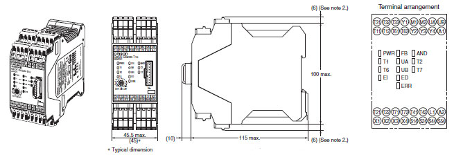
Note: 1. Above outline drawing is for -RC terminal type.
2. For -RC terminal type only.
Expansion Unit
G9SX-EX401-[]
Expansion Unit (OFF-delayed Model)
G9SX-EX041-T-[]
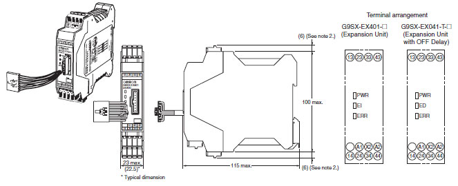
Note: 1. Above outline drawing is for -RC terminal type.
2. For -RC terminal type only.
last update: November 6, 2012
- NO. G9SX-GS
- TYPE:Safety Units / Safety Relay Units G9SX-series Flexible Safety Units
 Copyright Statement
 - DATE:2021-06-12
- Associated products:
G9SX Flexible Safety Unit/Features G9SX-SM Standstill Monitoring Unit/Features