OMRON E5AN-H, E5EN-HControl Components/ Temperature Controllers/General-purpose
OMRON E5AN-H, E5EN-H Control Components
- E5AN-H, E5EN-H Advanced Digital Temperature Controller (96 x 96 mm and 48 x 96 mm)/Dimensions
- E5AN-H, E5EN-H Advanced Digital Temperature Controller (96 x 96 mm and 48 x 96 mm)/Catalog
- E5AN-H, E5EN-H Advanced Digital Temperature Controller (96 x 96 mm and 48 x 96 mm)/Lineup
- E5AN-H, E5EN-H Advanced Digital Temperature Controller (96 x 96 mm and 48 x 96 mm)/Specifications
- Purchase the OMRON E5AN-H, E5EN-H General-purpose
OMRON E5AN-H, E5EN-H Dimensions
/Images/l_1947-25-118764-198x198.jpglast update: June 25, 2018
• High-resolution display with 5 digits/0.01°C display.
• High-speed sampling cycle of 60 ms.
• High Accuracy
Thermocouple/Pt input: ±0.1% of PV
Analog input: ±0.1% FS
• Universal inputs on all models (thermocouple, PT, or analog input) to handle various sensors with one Controller. Models also available with Remote SP.
• A PV/SV-status display function can be set to automatically alternate between displaying the status of the Temperature Controller (auto/manual, RUN/STOP, and alarms) and the PV or SV.
• Flexible contact outputs with logic operations (AND, OR, and delays) set from the Support Software (CX-Thermo Ver. 4.0)
• Preventive maintenance for relays in the Temperature Controller using a Control Output ON/OFF Counter.
• Model available with position-proportional control
Main I/O Functions

last update: June 25, 2018
Purchase the OMRON General-purpose Please fill in the following
If you have just landed here, this product OMRON E5AN-H, E5EN-H Control Components,Control Components is offered online by Tianin FLD Technical Co.,Ltd. This is an online store providing Control Components at wholesale prices for consumers. You can call us or send enquiry, we would give you the prices, packing,deliverty and more detailed information on the E5AN-H, E5EN-H We cooperate with DHL,TNT,FEDEX,UPS,EMS,etc.They guarantee to meet your needs in terms of time and money,even if you need your OMRON E5AN-H, E5EN-HControl Components tomorrow morning (aka overnight or next day air) on your desk, 2, 3 days or more.Note to international customers, YES, we ship worldwide.
H3RN-[]-B Solid-state timer/Features
CJ1M-CPU1[]-ETN SYSMAC CJ-series CJ1M CPU Units (with Ethernet function)/Features
CS1W-PPS01 SYSMAC CS-series Process Analog I/O Units/Features
WS02-CFDC1, 3G8E2-DRM21-V1 DeviceNet Configurator/Features
SRM1-C01 / C02-V2 Master Control Units (S-Controllers)/Features
OMRON E5AN-H, E5EN-H dimension
E5AN-H, E5EN-H Advanced Digital Temperature Controller (96 x 96 mm and 48 x 96 mm)/Dimensionslast update: December 21, 2018
(Unit: mm)
E5AN-H
E5EN-H
Accessories (Order Separately)
USB-Infrared Conversion Cable
E58-CIFIR
USB-Serial Conversion Cable
E58-CIFQ1
Terminal Covers
E53-COV16 (Six Covers provided.)
Mounting Brackets
Y92H-9 (2pcs)
One set is packaged with the product.
Order Mounting Brackets separately if yours are lost or damaged.
Waterproof Packing
Y92S-P4 (for DIN 96 x 96)
Y92S-P5 (for DIN 48 x 96)
Order the Waterproof Packing separately if it becomes lost or damaged.
The Waterproof Packing can be used to achieve an IP66 degree of protection.
(Deterioration, shrinking, or hardening of the waterproof packing may occur depending on the operating environment. Therefore, periodic replacement is recommended to ensure the level of waterproofing specified in IP66. The time for periodic replacement depends on the operating environment. Be sure to confirm this point at your site. Consider one year a rough standard. OMRON shall not be liable for the level of water resistance if the customer does not perform periodic replacement.)
The Waterproof Packing does not need to be attached if a waterproof structure is not required.
Current Transformers
E54-CT1
E54-CT3
E54-CT3 Accessory
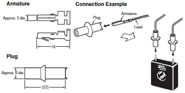
E54-CT1
Thru-current (Io) vs. Output Voltage (Eo) (Reference Values)
Maximum continuous heater current: 50 A (50/60 Hz)
Number of windings: 400±2
Winding resistance: 18±2 Ω
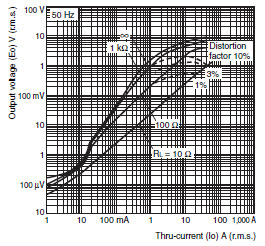
E54-CT3
Thru-current (Io) vs. Output Voltage (Eo) (Reference Values)
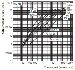
Maximum continuous heater current: 120 A (50/60 Hz)
(Maximum continuous heater current for an OMRON Temperature Controller is 50 A.)
Number of windings: 400±2
Winding resistance: 8±0.8 Ω
last update: December 21, 2018
OMRON E5AN-H, E5EN-H catalog
E5AN-H, E5EN-H Advanced Digital Temperature Controller (96 x 96 mm and 48 x 96 mm)/Catalog- Catalog
- Manual
- CAD
English
Global Edition
| Catalog Name | Catalog Number [size] | Last Update | |
|---|---|---|---|
| | - [2622KB] | Dec 21, 201820181221 | E5AN-H, E5EN-H Data Sheet |
| | - [1325KB] | Apr 03, 201720170403 | Safety Precautions for E5[]N, E5[]N-H, E5[]N-HT |
| | - [1526KB] | Apr 03, 201720170403 | Operation for E5[]N, E5[]N-H, E5[]N-HT |
OMRON E5AN-H, E5EN-H lineup
E5AN-H, E5EN-H Advanced Digital Temperature Controller (96 x 96 mm and 48 x 96 mm)/Lineuplast update: December 21, 2018
E5AN-H
| Size | Case color | Power supply voltage | Control method | Auxiliary output | Control output 1/2 | Heater burnout | Optional functions | Model | ||
|---|---|---|---|---|---|---|---|---|---|---|
| Event inputs | Transfer output | RSP | ||||||||
| 1/4 DIN 96 × 96 × 78 (W × H × D) | Black | 100 to 240 VAC | Basic | 2 | Control Output Unit × 2 | 1 | 2 | 4 to 20- mA input | E5AN-HAA2HBM-500 | |
| SSR outputs × 2 | 1 | 2 | 4 to 20- mA input | E5AN-HSS2HBM-500 * | ||||||
| Control Output Unit × 2 | 2 | 2 | 4 to 20- mA output | 4 to 20- mA input | E5AN-HAA2HHBFM-500 | |||||
| SSR outputs × 2 | 2 | 2 | 4 to 20- mA output | 4 to 20- mA input | E5AN-HSS2HHBFM-500 * | |||||
| 3 | Control Output Unit × 2 | 2 | 4 to 20- mA output | 4 to 20- mA input | E5AN-HAA3BFM-500 | |||||
| SSR outputs × 2 | 2 | 4 to 20- mA output | 4 to 20- mA input | E5AN-HSS3BFM-500 * | ||||||
| Valve | 2 | Relay outputs × 2 | 2 | 4 to 20- mA input | E5AN-HPRR2BM-500 | |||||
| Relay outputs × 2 | 2 | 4 to 20- mA output | 4 to 20- mA input | E5AN-HPRR2BFM-500 | ||||||
| 24 VAC/ VDC | Basic | 2 | Control Output Unit × 2 | 1 | 2 | 4 to 20- mA input | E5AN-HAA2HBMD-500 | |||
| SSR outputs × 2 | 1 | 2 | 4 to 20- mA input | E5AN-HSS2HBMD-500 * | ||||||
| Control Output Unit × 2 | 2 | 2 | 4 to 20- mA output | 4 to 20- mA input | E5AN-HAA2HHBFMD-500 | |||||
| SSR outputs × 2 | 2 | 2 | 4 to 20- mA output | 4 to 20- mA input | E5AN-HSS2HHBFMD-500 * | |||||
| 3 | Control Output Unit × 2 | 2 | 4 to 20- mA output | 4 to 20- mA input | E5AN-HAA3BFMD-500 | |||||
| SSR outputs × 2 | 2 | 4 to 20- mA output | 4 to 20- mA input | E5AN-HSS3BFMD-500 * | ||||||
| Valve | 2 | Relay outputs × 2 | 2 | 4 to 20- mA input | E5AN-HPRR2BMD-500 | |||||
| Relay outputs × 2 | 2 | 4 to 20- mA output | 4 to 20- mA input | E5AN-HPRR2BFMD-500 | ||||||
| Silver | 100 to 240 VAC | Basic | 2 | Control Output Unit × 2 | 1 | 2 | 4 to 20- mA input | E5AN-HAA2HBM-W-500 | ||
| Control Output Unit × 2 | 2 | 2 | 4 to 20- mA output | 4 to 20- mA input | E5AN-HAA2HHBFM-W-500 | |||||
| 24 VAC/ VDC | Control Output Unit × 2 | 1 | 2 | 4 to 20- mA input | E5AN-HAA2HBMD-W-500 | |||||
* Orders will not be accepted after March 31, 2018.
E5EN-H
| Size | Case color | Power supply voltage | Control method | Auxiliary output | Control output 1/2 | Heater burnout | Optional functions | Model | ||
|---|---|---|---|---|---|---|---|---|---|---|
| Event inputs | Transfer output | RSP | ||||||||
| 1/8 DIN 48 × 96 × 78 (W × H × D) | Black | 100 to 240 VAC | Basic | 2 | Control Output Unit × 2 | 1 | 2 | 4 to 20- mA input | E5EN-HAA2HBM-500 | |
| SSR outputs × 2 | 1 | 2 | 4 to 20- mA input | E5EN-HSS2HBM-500 * | ||||||
| Control Output Unit × 2 | 2 | 2 | 4 to 20- mA output | 4 to 20- mA input | E5EN-HAA2HHBFM-500 | |||||
| SSR outputs × 2 | 2 | 2 | 4 to 20- mA output | 4 to 20- mA input | E5EN-HSS2HHBFM-500 * | |||||
| 3 | Control Output Unit × 2 | 2 | 4 to 20- mA output | 4 to 20- mA input | E5EN-HAA3BFM-500 | |||||
| SSR outputs × 2 | 2 | 4 to 20- mA output | 4 to 20- mA input | E5EN-HSS3BFM-500 * | ||||||
| Valve | 2 | Relay outputs × 2 | 2 | 4 to 20- mA input | E5EN-HPRR2BM-500 | |||||
| Relay outputs × 2 | 2 | 4 to 20- mA output | 4 to 20- mA input | E5EN-HPRR2BFM-500 | ||||||
| 24 VAC/ VDC | Basic | 2 | Control Output Unit × 2 | 1 | 2 | 4 to 20- mA input | E5EN-HAA2HBMD-500 | |||
| SSR outputs × 2 | 1 | 2 | 4 to 20- mA input | E5EN-HSS2HBMD-500 * | ||||||
| Control Output Unit × 2 | 2 | 2 | 4 to 20- mA output | 4 to 20- mA input | E5EN-HAA2HHBFMD-500 | |||||
| SSR outputs × 2 | 2 | 2 | 4 to 20- mA output | 4 to 20- mA input | E5EN-HSS2HHBFMD-500 * | |||||
| 3 | Control Output Unit × 2 | 2 | 4 to 20- mA output | 4 to 20- mA input | E5EN-HAA3BFMD-500 | |||||
| SSR outputs × 2 | 2 | 4 to 20- mA output | 4 to 20- mA input | E5EN-HSS3BFMD-500 * | ||||||
| Valve | 2 | Relay outputs × 2 | 2 | 4 to 20- mA input | E5EN-HPRR2BMD-500 | |||||
| Relay outputs × 2 | 2 | 4 to 20- mA output | 4 to 20- mA input | E5EN-HPRR2BFMD-500 | ||||||
| Silver | 100 to 240 VAC | Basic | 2 | Control Output Unit × 2 | 1 | 2 | 4 to 20- mA input | E5EN-HAA2HBM-W-500 | ||
| Control Output Unit × 2 | 2 | 2 | 4 to 20- mA output | 4 to 20- mA input | E5EN-HAA2HHBFM-W-500 | |||||
| 24 VAC/ VDC | Control Output Unit × 2 | 1 | 2 | 4 to 20- mA input | E5EN-HAA2HBMD-W-500 | |||||
* Orders will not be accepted after March 31, 2018.
Accessories (Order Separately)
| Output unit | Model | Specifications |
|---|---|---|
| Relay output | E53-RN | SPST-NO, 250 VAC, 5 A (resistive load), electrical life: 100,000 operations |
| Voltage output (for driving SSR) | E53-QN | 12 VDC (PNP), max. load current: 40-mA, with short-circuit protection |
| E53-Q3 | 24 VDC (NPN), max. load current: 20-mA, with short-circuit protection | |
| E53-Q4 | 24 VDC (PNP), max. load current: 20-mA, with short-circuit protection | |
| Current output | E53-C3N | 4 to 20-mA DC, load: 600 Ω max., resolution: approx. 10,000 |
| E53-C3DN | 0 to 20-mA DC, load: 600 Ω max., resolution: approx. 10,000 | |
| Linear voltage output | E53-V34N | 0 to 10 VDC, load: 1 kΩ min., resolution: approx. 10,000 |
| E53-V35N | 0 to 5 VDC, load: 1 kΩ min., resolution: approx. 10,000 |
USB-infrared Conversion Cable
| Model |
|---|
| E58-CIFIR |
USB-Serial Conversion Cable
| Model |
|---|
| E58-CIFQ1 |
Terminal Cover
| Connectable models | Model |
|---|---|
| E5AN-H | E53-COV16 |
| E5EN-H |
Note: The Terminal Cover comes with the E5CN-[][][]-500 models.
Mounting Brackets
| Model |
|---|
| Y92H-9 |
Note: These Mounting Brackets are provided with the Digital Controller.
Waterproof Packing
| Connectable models | Model |
|---|---|
| E5AN-H | Y92S-P4 |
| E5EN-H | Y92S-P5 |
Note: The Waterproof Packing is included with the Controller.
Current Transformers (CTs)
| Hole diameter | Model |
|---|---|
| 5.8 dia. | E54-CT1 |
| 12.0 dia. | E54-CT3 |
CX-Thermo Support Software
| Model |
|---|
| EST2-2C-MV4 |
last update: December 21, 2018
OMRON E5AN-H, E5EN-H specification
E5AN-H, E5EN-H Advanced Digital Temperature Controller (96 x 96 mm and 48 x 96 mm)/Specificationslast update: June 25, 2018
Ratings
| Power supply voltage | No D in model number: 100 to 240 VAC, 50/60 Hz D in model number: 24 VAC, 50/60 Hz; 24 VDC | |
|---|---|---|
| Operating voltage range | 85% to 110% of rated supply voltage | |
| Power consumption | 100 to 240 VAC: 12 VA 24 VAC/VDC: 8.5 VA (24 VAC)/5.5 W (24 VDC) | |
| Sensor input | Any of the following can be selected. Thermocouple: K, J, T, E, L, U, N, R, S, B, W, or PL II Platinum resistance thermometer: Pt100 or JPt100 Current input: 4 to 20 mA or 0 to 20 mA Voltage input: 1 to 5 V, 0 to 5 V, or 0 to 10 V | |
| Input impedance | Current input: 150 Ω max., Voltage input: 1 MΩ min. (Use a 1:1 connection when connecting the ES2-HB-N.) | |
| Control method | ON/OFF control or 2-PID control (with auto-tuning) | |
| Control output | Relay output | Output Unit (Install the Output Unit (sold separately).) |
| Voltage output (for driving SSR) | ||
| Current output | ||
| Linear voltage output | ||
| Relay output for position- proportional control | Relay output: Open and close: SPST-NO, 250 VAC, 1 A (including in-rush current), electrical life: 100,000 operations min. Potentiometer input: Must be between 100 Ω and 2.5 kΩ for maximum open position. | |
| Auxiliary output | Number of outputs | 2 or 3 max. |
| Output specifications | Relay output: SPST-NO, 250 VAC, 3 A (resistive load), electrical life: 100,000 operations, minimum applicable load: 5 V, 10 mA | |
| Event input | Number of outputs | 2 or 4 (with an E53-AKB) |
| External contact input specifications | Contact input: ON: 1 kΩ max., OFF: 100 kΩ min. | |
| Non-contact input: ON: Residual voltage: 1.5 V max., OFF: Leakage current: 0.1 mA max. | ||
| Current flow: Approx. 7 mA per contact | ||
| Logic operations | Number of operations | 8 max. |
| Operations | • Logic operation: Any of the following four patterns can be selected. The input status may be inverted. (A and B) or (C and D), (A or C) and (B or D), A or B or C or D, A and B and C and D (A, B, C, and D are four inputs.) • Delay: ON delay or OFF delay for the results of the logic operation given above. Setting time: 0 to 9999 s or 0 to 9999 min • Output inversion: Possible | |
| Output | One work bit per operation | |
| Work bit assignment | Any of The following can be assigned to up to eight work bits (logic operation results): Event input operations, auxiliary outputs, or control outputs. | |
| Transfer outputs | Number of outputs | 1 max. (Depends on model. Models with transfer output (F in model number) |
| Output specifications | Current output: 4 to 20 mA DC, Load: 600 Ω max., Resolution at 4 to 20 mA: Approx. 10,000 | |
| RSP input | Number of inputs | 1 |
| Signal type | Current input: 4 to 20 mA (input impedance: 150 Ω ±10%) | |
| Analog input scaling | Scaling of signal to engineering units (EU) -19,999 to 30,000 (display: 30,000 max.) | |
| Accuracy | (±0.2% of FS) ±1 digit max. | |
| Input sampling period | 60 ms | |
| Setting method | Set digitally using keys on the front panel or by using the RSP input. | |
| Indication method | 11-segment digital display and individual indicators (7-segments displays also possible) Character height: E5AN-H: PV: 15.8 mm, SV: 9.5 mm, MV: 6.8 mm; E5EN-H: PV: 11.8 mm, SV: 8.1 mm, MV: 5.8 mm Content of 3-level display: PV/SV/MV, PV/SV/Bank No., or soak time remain Number of digits: 5 for PV and SV, 4 for MV | |
| Bank switching | Supported (number of banks: 8) Local SP, alarm settings, PID sets (PID constants, MV upper limit, MV lower limit, etc.) | |
| Other functions | Manual output, heating/cooling control, loop burnout alarm, SP ramp, other alarm functions, heater burnout detection, 40% AT, 100% AT, MV limiter, input digital filter, self-tuning, temperature input shift, run/stop, protection functions, control output ON/OFF counter, extraction of square root, MV change rate limit, PV/SV status display, logic operations, automatic cooling coefficient adjustment | |
| Ambient operating temperature | -10 to 55°C (with no condensation or icing), for 3-year warranty: -10 to 50°C | |
| Ambient operating humidity | 25% to 85% | |
| Storage temperature | -25 to 65°C (with no condensation or icing) | |
Input Ranges
Thermocouple/Platinum Resistance Thermometer (Fully Universal Inputs)
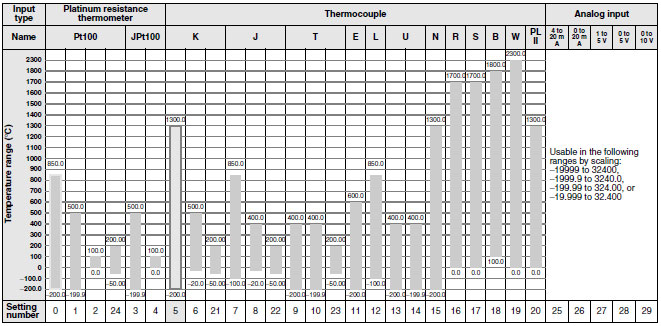
Shaded settings are the default settings.
The applicable standards for the input types are as follows:
K, J, T, E, N, R, S, B: JIS C 1602-1995, IEC 584-1
L: Fe-CuNi, DIN 43710-1985
U: Cu-CuNi, DIN 43710-1985
W: W5Re/W26Re, ASTM E988-1990
JPt100: JIS C 1604-1989, JIS C 1606-1989
Pt100: JIS C 1604-1997, IEC 751
PL II: According to Platinel II electromotive force charts from BASF (previously Engelhard)
Alarm Outputs
Each alarm can be independently set to one of the following 13 alarm types. The default is 2: Upper limit.
Auxiliary outputs are allocated for alarms. ON delays and OFF delays (0 to 999 s) can also be specified.
Note: For models with heater burnout, SSR failure, and heater overcurrent detection, alarm 1 will be an OR output of the
alarm selected from the following alarm types and the alarms for heater burnout, SSR failure, and heater
overcurrent. To output only a heater burnout alarm, SSR failure alarm, and heater overcurrent alarm for alarm 1,
set the alarm type to 0 (i.e., no alarm function).
| Set value | Alarm type | Alarm output operation | Description of function | |
|---|---|---|---|---|
| When alarm value X is positive | When alarm value X is negative | |||
| 0 | Alarm function OFF | Output OFF | No alarm | |
| 1 | Upper- and lower-limit *1 |  | *2 | Set the deviation in the set point by setting the alarm upper limit (H) and alarm lower limit (L). |
| 2 | Upper-limit |  |  | Set the upward deviation in the set point by setting the alarm value (X). |
| 3 | Lower-limit |  |  | Set the downward deviation in the set point by setting the alarm value (X). |
| 4 | Upper- and lower-limit range *1 |  | *3 | Set the deviation in the set point by setting the alarm upper limit (H) and alarm lower limit (L). |
| 5 | Upper- and lower-limit with standby sequence *1 |  *5 *5 | *4 | A standby sequence is added to the upper- and lower-limit alarm (1). *7 |
| 6 | Upper-limit with standby sequence |  |  | A standby sequence is added to the upper-limit alarm (2). *7 |
| 7 | Lower-limit with standby sequence |  |  | A standby sequence is added to the lower-limit alarm (3). *7 |
| 8 | Absolute-value upper-limit |  |  | The alarm will turn ON if the process value is larger than the alarm value (X) regardless of the set point. |
| 9 | Absolute-value lower-limit |  |  | The alarm will turn ON if the process value is smaller than the alarm value (X) regardless of the set point. |
| 10 | Absolute-value upper-limit with standby sequence |  |  | A standby sequence is added to the absolute-value upper-limit alarm (8). *7 |
| 11 | Absolute-value lower-limit with standby sequence |  |  | A standby sequence is added to the absolute-value lower-limit alarm (9). *7 |
| 12 | LBA (alarm 1 type only) | --- | Refer to Data Sheet. | |
| 13 | PV change rate alarm | --- | Refer to Data Sheet. | |
| 14 | RSP absolute value upper limit *6 | | | The alarm turns ON when the remote SP (RSP) is larger than the alarm value (X). This alarm functions in both Local SP and Remote SP Modes. |
| 15 | RSP absolute value lower limit *6 | | | The alarm turns ON when the remote SP (RSP) is smaller than the alarm value (X). This alarm functions in both Local SP and Remote SP Modes. |
*1. With set values 1, 4 and 5, the upper and lower limit values can be set independently for each alarm type, and are
expressed as "L" and "H."
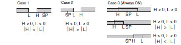
*2. Set value: 1, Upper- and lower-limit alarm
*3. Set value: 4, Upper- and lower-limit range
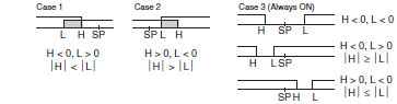
*4. Set value: 5, Upper- and lower-limit with standby sequence
For Upper- and Lower-Limit Alarm Described Above
• Case 1 and 2
Always OFF when the upper-limit and lower-limit hysteresis overlaps.
• Case 3: Always OFF
*5. Set value: 5, Upper- and lower-limit with standby sequence
Always OFF when the upper-limit and lower-limit hysteresis overlaps.
*6. Displayed when there is a remote SP input.
*7. Refer to the E5CN/E5AN/E5EN/E5GN Digital Temperature Controllers User's Manual Basic Type (Cat. No. H156) for
information on the operation of the standby sequence.
*8. Refer to the E5CN/E5AN/E5EN/E5GN Digital Temperature Controllers User's Manual Basic Type (Cat. No. H156) for
information on the loop burnout alarm (LBA).
*9. Refer to the E5CN/E5AN/E5EN/E5GN Digital Temperature Controllers User's Manual Basic Type (Cat. No. H156) for
information on the PV change rate alarm.
Characteristics
| Indication accuracy | Thermocouple: (±0.1% of indicated value or ±1°C, whichever is greater) ±1 digit max. *1 Platinum resistance thermometer: (±0.1% of indicated value or ±0.5°C, whichever is greater) ±1 digit max. Analog input: ±0.1% FS ±1 digit max. CT input: ±5% FS ±1 digit max. Potentiometer input: ±5% FS ±1 digit max. | |
|---|---|---|
| Transfer output accuracy | ±0.3% FS max. | |
| Influence of temperature *2 | Thermocouple input (R, S, B, W, PL II): (±1% of PV or ±10°C, whichever is greater) ±1 digit max. Other thermocouple input: (±1% of PV or ±4°C, whichever is greater) ±1 digit max. *3 Platinum resistance thermometer: (±1% of PV or ±2°C, whichever is greater) ±1 digit max. Analog input: (±1%FS) ±1 digit max. | |
| Influence of voltage *2 | ||
| Influence of EMS. (at EN 61326-1) | ||
| Input sampling period | 60 ms | |
| Hysteresis | Temperature input: 0.1 to 3240.0°C or °F (in units of 0.1°C or °F) Analog input: 0.01% to 99.99% FS (in units of 0.01% FS) | |
| Proportional band (P) | Temperature input: 0.1 to 3240.0°C or °F (in units of 0.1°C or °F) Analog input: 0.1% to 999.9% FS (in units of 0.1% FS) | |
| Integral time (I) | 0.0 to 3240.0 s (in units of 0.1 s) | |
| Derivative time (D) | 0.0 to 3240.0 s (in units of 0.1 s) | |
| Control period | 0.5, 1 to 99 s (in units of 1 s) | |
| Manual reset value | 0.0 to 100.0% (in units of 0.1%) | |
| Alarm setting range | -19999 to 32400 (decimal point position depends on input type) | |
| Affect of signal source resistance | Thermocouple: 0.1°C/Ω max. (100 Ω max.) Platinum resistance thermometer: 0.1°C/Ω max. (10 Ω max.) | |
| Insulation resistance | 20 MΩ min. (at 500 VDC) | |
| Dielectric strength | 2,300 VAC, 50 or 60 Hz for 1 min (between terminals with different charge) | |
| Vibration resistance | Malfunction | 10 to 55 Hz, 20 m/s2 for 10 min each in X, Y, and Z directions |
| Destruction | 10 to 55 Hz, 0.75-mm single amplitude for 2 hrs each in X, Y, and Z directions | |
| Shock resistance | Malfunction | 100 m/s2, 3 times each in X, Y, and Z directions |
| Destruction | 300 m/s2, 3 times each in X, Y, and Z directions | |
| Weight | E5AN-H | Controller: Approx. 310 g, Mounting Bracket: Approx. 100 g |
| E5EN-H | Controller: Approx. 260 g, Mounting Bracket: Approx. 100 g | |
| Degree of protection | Front panel: IP66, Rear case: IP20, Terminals: IP00 | |
| Memory protection | Non-volatile memory (number of writes: 1,000,000 times) | |
| Setup Tool | CX-Thermo version 4.0 or higher | |
| Setup Tool port | Provided on the bottom of the E5AN-H and E5EN-H. An E58-CIFQ1 USB-Serial Conversion Cable is required to connect the computer to the E5AN-H and E5EN-H. Provided on the front of the E5AN-H and E5EN-H. An E58-CIFIR USB-infrared Conversion Cable is required to connect the computer to the E5AN-H or E5EN-H. *4 | |
| Standards | Approved standards | UL 61010-1, CSA C22.2 No. 1010-1 |
| Conformed standards | EN 61010-1 (IEC 61010-1): Pollution level 2, overcurrent category II, Lloyd's standards *5 | |
| EMC | EMI: EN 61326-1 *6 Radiated Interference Electromagnetic Field Strength: EN 55011 Group 1, class A Noise Terminal Voltage: EN 55011 Group 1, class A EMS: EN 61326-1 *6 ESD Immunity: EN 61000-4-2 Electromagnetic Field Immunity: EN 61000-4-3 Burst Noise Immunity: EN 61000-4-4 Conducted Disturbance Immunity: EN 61000-4-6 Surge Immunity: EN 61000-4-5 Power Frequency Magnetic Field Immunity: EN 61000-4-8 Voltage Dip/Interrupting Immunity: EN 61000-4-11 | |
*1. The indication accuracy of K thermocouples in the −200 to 1300°C range, T and N thermocouples at a temperature of
−100°C max., and U and L thermocouples at any temperatures is ±2°C ±1 digit max. The indication accuracy of the
B thermocouple at a temperature of 400°C max. is not specified. The indication accuracy of B thermocouples in the
400 to 800°C range is ±3°C max. The indication accuracy of the R and S thermocouples at a temperature of 200°C
max. is ±3°C ±1 digit max. The indication accuracy of W thermocouples is ±0.3% of PV or ±3°C, whichever is
greater, ±1 digit max.
The indication accuracy of PL II thermocouples is ±0.3% of PV or ±2°C, whichever is greater, ±1 digit max.
*2. Ambient temperature: −10°C to 23°C to 55°C, Voltage range: −15% to 10% of rated voltage
*3. K thermocouple at −100°C max.: ±10°C max.
*4. External communications (RS-232C, RS-485, or RS-422) and cable communications for the Setup Tool can be used
at the same time.
*5. Refer to information on maritime standards in Safety Precautions for E5[]N/E5[]N-H for compliance with Lloyd's
Standards.
*6. Industrial electromagnetic environment (EN/IEC 61326-1 Table 2)
USB-Serial Conversion Cable
| Applicable OS | Windows XP/Vista/7/8 |
|---|---|
| Applicable software | CX-Thermo version 4 or higher |
| Applicable models | E5AN/E5EN/E5CN/E5CN-U/E5AN-H/E5EN-H/E5CN-H |
| USB interface standard | Conforms to USB Specification 1.1. |
| DTE speed | 38400 bps |
| Connector specifications | Computer: USB (type A plug) Temperature Controller: Setup Tool port (on bottom of Controller) |
| Power supply | Bus power (Supplied from USB host controller.) |
| Power supply voltage | 5 VDC |
| Current consumption | 70 mA |
| Ambient operating temperature | 0 to 55°C (with no condensation or icing) |
| Ambient operating humidity | 10% to 80% |
| Storage temperature | - 20 to 60°C (with no condensation or icing) |
| Storage humidity | 10% to 80% |
| Altitude | 2,000 m max. |
| Weight | Approx. 100 g |
Note: A driver must be installed in the personal computer. Refer to installation information in the operation manual for the
Conversion Cable.
Communications Specifications
| Transmission line connection method | RS-485, RS-422: Multipoint RS-232C: Point-to-point |
|---|---|
| Communications | RS-485 (two-wire, half duplex) RS-422 (four-wire, half duplex) or RS-232C |
| Synchronization method | Start-stop synchronization |
| Protocol | CompoWay/F, SYSWAY, or Modbus |
| Baud rate | 1200, 2400, 4800, 9600, 19200, 38400, or 57600 bps |
| Transmission code | ASCII (CompoWay/F, SYSWAY) RTU (Modbus) |
| Data bit length * | 7 or 8 bits |
| Stop bit length * | 1 or 2 bits |
| Error detection | Vertical parity (none, even, odd) Frame check sequence (FCS) with SYSWAY Block check character (BCC) with CompoWay/F or CRC-16 Modbus |
| Flow control | None |
| Interface | RS-485, RS-422, or RS-232C |
| Retry function | None |
| Communications buffer | 217 bytes |
| Communications response wait time | 0 to 99 ms Default: 20 ms |
* The baud rate, data bit length, stop bit length, and vertical parity can be individually set using the Communications
Setting Level.
Current Transformer (Order Separately) Ratings
| Dielectric strength | 1,000 VAC for 1 min |
|---|---|
| Vibration resistance | 50 Hz, 98 m/s2 |
| Weight | E54-CT1: Approx. 11.5 g, E54-CT3: Approx. 50 g |
| Accessories (E54-CT3 only) | Armatures (2) Plugs (2) |
USB-Infrared Conversion Cable
| Applicable OS | Windows XP/Vista/7/8 |
|---|---|
| Applicable software | CX-Thermo version 4.0 or higher |
| Applicable models | E5AN-H/E5EN-H |
| USB interface standard | Conforms to USB Specification 1.1. |
| DTE speed | 38400 bps |
| Connector specifications | Computer: USB (type A plug) Temperature Controller: Infrared port (on front of Controller) |
| Power supply | Bus power (Supplied from USB host controller.) |
| Power supply voltage | 5 VDC |
| Current consumption | 80 mA |
| Ambient operating temperature | 0 to 55°C (with no condensation or icing) |
| Ambient operating humidity | 10% to 80% |
| Storage temperature | - 20 to 60°C (with no condensation or icing) |
| Storage humidity | 10% to 80% |
| Altitude | 2,000 m max. |
| Weight | Approx. 130 g (with mounting adaptor) |
Note: A driver must be installed in the personal computer. Refer to installation information in the operation manual for the
Conversion Cable.
Heater Burnout Alarms, SSR Failure Alarms, and Heater Overcurrent Alarms
| CT input (for heater current detection) | Models with detection for single-phase heaters: One input Models with detection for single-phase or three-phase heaters: Two inputs |
|---|---|
| Maximum heater current | 50 A AC |
| Input current indication accuracy | ±5% FS ±1 digit max. |
| Heater burnout alarm setting range *1 | 0.1 to 49.9 A (in units of 0.1 A) Minimum detection ON time: 100 ms |
| SSR failure alarm setting range *2 | 0.1 to 49.9 A (in units of 0.1 A) Minimum detection OFF time: 100 ms |
| Heater overcurrent alarm setting range *3 | 0.1 to 49.9 A (in units of 0.1 A) Minimum detection ON time: 100 ms |
*1. For heater burnout alarms, the heater current will be measured when the control output is ON, and the output
assigned to the alarm 1 function will turn ON if the heater current is lower than the set value (i.e., heater burnout
detection current value).
*2. For SSR failure alarms, the heater current will be measured when the control output is OFF, and the output assigned
to the alarm 1 function will turn ON if the heater current is higher than the set value (i.e., SSR failure detection
current value).
*3. For heater overcurrent alarms, the heater current will be measured when the control output is ON, and the output
assigned to the alarm 1 function will turn ON if the heater current is higher than the set value (i.e., heater
overcurrent detection current value).
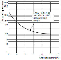
Electrical Life Expectancy Curve for Relays (Reference Values)
last update: June 25, 2018
- NO. E5AN-H, E5EN-H
- TYPE:Temperature Controllers General-purpose
 Copyright Statement
 - DATE:2021-06-07
- Associated products:
E5CN-H Advanced Digital Temperature Controller (48 x 48 mm)/Features E5AR Digital Controller/Features