OMRON 3G3MX2-V1Motion / Drives/ Inverters/ Copyright Statement
OMRON 3G3MX2-V1 Motion / Drives
OMRON 3G3MX2-V1 Dimensions
/Images/l_3164-25-162804-198x198.jpglast update: July 20, 2017
Amazing in Control
High starting torque and torque control capability in open loop mode give you full control of your machine dynamics and performance. Options for all of the major open network systems.
Torque master

The MX2-V1 delivers 200% starting torque near stand-still (0.5 Hz) and can operate in torque control in open loop mode. This allows the MX2-V1 to be used in applications where closed loop AC vector drives were previously used.
Easy network integration

Standard industrial networks, such as EtherCAT, CompoNet or DeviceNet as options. High-speed EtherCAT provides solutions for the entire system from input to output with Sysmac Series.
Easy communications setting

Built-in RS-485 Modbus communications. OMRON Function Blocks are available for the CP H/L and CJ-series PLCs. Those control the MX2-V1 via Modbus communications easily.
Safety in Control
Safety is embedded in the MX2-V1, according to ISO 13849-1, Cat. 3, with two safety inputs and an External Device Monitoring (EDM) output.
No external contactors on the motor side are required, meaning simpler wiring for the user.
Safety embedded; ISO 13849-1, Cat. 3

Dual contactors at the output of the inverter are no longer required.
Direct connection to a safety controller ensures compliance to ISO 13849-1, Cat. 3.
MOTOR CONTROL Permanent magnet motors

The PM motor conforming to high-efficiency regulations can be controlled. The PM motor promotes further energy saving and achieves earth-friendly machine control.
Position and run!
The MX2-V1 is a drive and position controller in one, ideal for modular machines where moderate positional accuracy is required. Speed synchronisation is also possible, with no additional programming required.
Speed synchronisation

With no external hardware required, and via standard parameter settings, speed synchronisation can be achieved. The MX2-V1 will act as a speed follower to an external pulse generator/encoder signal up to 32 KHz.
Positioning functionality

Specially developed application functionality enables the MX2-V1 to solve simple positioning tasks without the need for an external controller. Up to 8 positions, plus home, can be selected by the user, and furthermore, the MX2-V1 can be switched between speed and position mode.
Program and play!
The MX2-V1 gives you the power to create smart solutions using PLC functionality, as standard. Via an intuitive flow chart programming tool, you can create programs with up to 1000 lines of code and with 5 tasks running in parallel.
Free to program

• Intuitive and user friendly flow chart programming
• Integrated in CX-Drive
• Up to 1000 lines in a program
• 5 tasks can run in parallel
(CX-Drive version 2.80 or higher is required.)
last update: July 20, 2017
Purchase the OMRON Copyright Statement Please fill in the following
If you have just landed here, this product OMRON 3G3MX2-V1 Motion / Drives,Motion / Drives is offered online by Tianin FLD Technical Co.,Ltd. This is an online store providing Motion / Drives at wholesale prices for consumers. You can call us or send enquiry, we would give you the prices, packing,deliverty and more detailed information on the 3G3MX2-V1 We cooperate with DHL,TNT,FEDEX,UPS,EMS,etc.They guarantee to meet your needs in terms of time and money,even if you need your OMRON 3G3MX2-V1Motion / Drives tomorrow morning (aka overnight or next day air) on your desk, 2, 3 days or more.Note to international customers, YES, we ship worldwide.
UM, MC3 Safety Mat/Safety Mat Controller/Features
ZJ-BAS Ionizer (Digital Bar Type)/Features
61F-G[]N Floatless Level Switch (Compact Type)/Features
CP1W-EIP61 EtherNet/IP Communication Module for CP1L/CP1H PLCs/Features
3G8F7-DRM21-E DeviceNet Board (PCI Board)/Features
OMRON 3G3MX2-V1 specification
3G3MX2-V1 Multi-function Compact Inverter/Specificationslast update: August 1, 2018
Performance Specifications
Inverter MX2-series V1 type
3-phase 200 V Class
| Function name | 3-phase 200 V | |||||||
|---|---|---|---|---|---|---|---|---|
| Model name (3G3MX2-) | A2001-V1 | A2002-V1 | A2004-V1 | A2007-V1 | A2015-V1 | A2022-V1 | ||
| Applicable motor capacity | kW | CT | 0.1 | 0.2 | 0.4 | 0.75 | 1.5 | 2.2 |
| VT | 0.2 | 0.4 | 0.75 | 1.1 | 2.2 | 3.0 | ||
| HP | CT | 1/8 | 1/4 | 1/2 | 1 | 2 | 3 | |
| VT | 1/4 | 1/2 | 1 | 1 1/2 | 3 | 4 | ||
| Rated output capacity [kVA] | 200 V | CT | 0.2 | 0.5 | 1.0 | 1.7 | 2.7 | 3.8 |
| VT | 0.4 | 0.6 | 1.2 | 2.0 | 3.3 | 4.1 | ||
| 240 V | CT | 0.3 | 0.6 | 1.2 | 2.0 | 3.3 | 4.5 | |
| VT | 0.4 | 0.7 | 1.4 | 2.4 | 3.9 | 4.9 | ||
| Rated input voltage | 3-phase 200 V - 15% to 240 V + 10%, 50/60 Hz ± 5% | |||||||
| Rated input current [A] | CT | 1.0 | 1.6 | 3.3 | 6 | 9 | 12.7 | |
| VT | 1.2 | 1.9 | 3.9 | 7.2 | 10.8 | 13.9 | ||
| Rated output voltage | 3-phase 200 to 240 V (The output cannot exceed the incoming voltage). | |||||||
| Rated output current [A] | CT | 1.0 | 1.6 | 3.0 | 5.0 | 8.0 | 11.0 | |
| VT | 1.2 | 1.9 | 3.5 | 6.0 | 9.6 | 12.0 | ||
| Short-time deceleration braking torque (%) (Discharge Resistor not connected) | 50 | 50 | 50 | 50 | 50 | 20 | ||
| Braking Resistor circuit * | Regenerative braking | Built-in Braking Resistor circuit (separate Discharge Resistor) | ||||||
| Min. connectable resistance [Ω] | 100 | 100 | 100 | 50 | 50 | 35 | ||
| Weight [kg] | 1.0 | 1.0 | 1.1 | 1.2 | 1.6 | 1.8 | ||
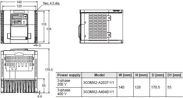
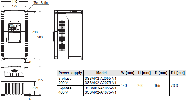
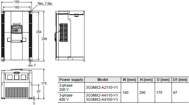
| Dimensions (width × height) [mm] | 68 × 128 | 108 × 128 | ||||||
| Dimensions (depth) [mm] | 109 | 122.5 | 145.5 | 170.5 | ||||
| Function name | 3-phase 200 V | ||||||
|---|---|---|---|---|---|---|---|
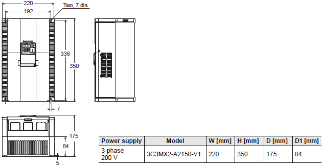
| Model name (3G3MX2-) | A2037-V1 | A2055-V1 | A2075-V1 | A2110-V1 | A2150-V1 | ||
| Applicable motor capacity | kW | CT | 3.7 | 5.5 | 7.5 | 11 | 15 |
| VT | 5.5 | 7.5 | 11 | 15 | 18.5 | ||
| HP | CT | 5 | 7 1/2 | 10 | 15 | 20 | |
| VT | 7 1/2 | 10 | 15 | 20 | 25 | ||
| Rated output capacity [kVA] | 200 V | CT | 6.0 | 8.6 | 11.4 | 16.2 | 20.7 |
| VT | 6.7 | 10.3 | 13.8 | 19.3 | 23.9 | ||
| 240 V | CT | 7.2 | 10.3 | 13.7 | 19.5 | 24.9 | |
| VT | 8.1 | 12.4 | 16.6 | 23.2 | 28.6 | ||
| Rated input voltage | 3-phase 200 V - 15% to 240 V + 10%, 50/60 Hz ± 5% | ||||||
| Rated input current [A] | CT | 20.5 | 30.8 | 39.6 | 57.1 | 62.6 | |
| VT | 23.0 | 37.0 | 48.0 | 68.0 | 72.0 | ||
| Rated output voltage | 3-phase 200 to 240 V (The output cannot exceed the incoming voltage). | ||||||
| Rated output current [A] | CT | 17.5 | 25.0 | 33.0 | 47.0 | 60.0 | |
| VT | 19.6 | 30.0 | 40.0 | 56.0 | 69.0 | ||
| Short-time deceleration braking torque (%) (Discharge Resistor not connected) | 20 | 20 | 20 | 10 | 10 | ||
| Braking Resistor circuit * | Regenerative braking | Built-in Braking Resistor circuit (separate Discharge Resistor) | |||||
| Min. connectable resistance [Ω] | 35 | 20 | 17 | 17 | 10 | ||
| Weight [kg] | 2.0 | 3.3 | 3.4 | 5.1 | 7.4 | ||
| Dimensions (width × height) [mm] | 140 × 128 | 140 × 260 | 180 × 296 | 220 × 350 | |||
| Dimensions (depth) [mm] | 170.5 | 155 | 175 | ||||
* The BRD usage is 10%.
3-phase 400 V Class
| Function name | 3-phase 400 V | ||||||
|---|---|---|---|---|---|---|---|
| Model name (3G3MX2-) | A4004-V1 | A4007-V1 | A4015-V1 | A4022-V1 | A4030-V1 | ||
| Applicable motor capacity | kW | CT | 0.4 | 0.75 | 1.5 | 2.2 | 3.0 |
| VT | 0.75 | 1.5 | 2.2 | 3.0 | 4.0 | ||
| HP | CT | 1/2 | 1 | 2 | 3 | 4 | |
| VT | 1 | 2 | 3 | 4 | 5 | ||
| Rated output capacity [kVA] | 380 V | CT | 1.1 | 2.2 | 3.1 | 3.6 | 4.7 |
| VT | 1.3 | 2.6 | 3.5 | 4.5 | 5.7 | ||
| 480 V | CT | 1.4 | 2.8 | 3.9 | 4.5 | 5.9 | |
| VT | 1.7 | 3.4 | 4.4 | 5.7 | 7.3 | ||
| Rated input voltage | 3-phase 380 V - 15% to 480 V + 10%, 50/60 Hz ± 5% | ||||||
| Rated input current [A] | CT | 1.8 | 3.6 | 5.2 | 6.5 | 7.7 | |
| VT | 2.1 | 4.3 | 5.9 | 8.1 | 9.4 | ||
| Rated output voltage | 3-phase 380 to 480 V (The output cannot exceed the incoming voltage). | ||||||
| Rated output current [A] | CT | 1.8 | 3.4 | 4.8 | 5.5 | 7.2 | |
| VT | 2.1 | 4.1 | 5.4 | 6.9 | 8.8 | ||
| Short-time deceleration braking torque (%) (Discharge Resistor not connected) | 50 | 50 | 50 | 20 | 20 | ||
| Braking Resistor circuit * | Regenerative braking | Built-in Braking Resistor circuit (separate Discharge Resistor) | |||||
| Min. connectable resistance [Ω] | 180 | 180 | 180 | 100 | 100 | ||
| Weight [kg] | 1.5 | 1.6 | 1.8 | 1.9 | 1.9 | ||
| Dimensions (width × height) [mm] | 108 × 128 | ||||||
| Dimensions (depth) [mm] | 143.5 | 170.5 | |||||
| Function name | 3-phase 400 V | ||||||
|---|---|---|---|---|---|---|---|
| Model name (3G3MX2-) | A4040-V1 | A4055-V1 | A4075-V1 | A4110-V1 | A4150-V1 | ||
| Applicable motor capacity | kW | CT | 4.0 | 5.5 | 7.5 | 11 | 15 |
| VT | 5.5 | 7.5 | 11 | 15 | 18.5 | ||
| HP | CT | 5 | 7 1/2 | 10 | 15 | 20 | |
| VT | 7 1/2 | 10 | 15 | 20 | 25 | ||
| Rated output capacity [kVA] | 380 V | CT | 6.0 | 9.7 | 11.8 | 15.7 | 20.4 |
| VT | 7.3 | 11.5 | 15.1 | 20.4 | 25.0 | ||
| 480 V | CT | 7.6 | 12.3 | 14.9 | 19.9 | 25.7 | |
| VT | 9.2 | 14.5 | 19.1 | 25.7 | 31.5 | ||
| Rated input voltage | 3-phase 380 V - 15% to 480 V + 10%, 50/60 Hz ± 5% | ||||||
| Rated input current [A] | CT | 11.0 | 16.9 | 18.8 | 29.4 | 35.9 | |
| VT | 13.3 | 20.0 | 24.0 | 38.0 | 44.0 | ||
| Rated output voltage | 3-phase 380 to 480 V (The output cannot exceed the incoming voltage). | ||||||
| Rated output current [A] | CT | 9.2 | 14.8 | 18.0 | 24.0 | 31.0 | |
| VT | 11.1 | 17.5 | 23.0 | 31.0 | 38.0 | ||
| Short-time deceleration braking torque (%) (Discharge Resistor not connected) | 20 | 20 | 20 | 10 | 10 | ||
| Braking Resistor circuit * | Regenerative braking | Built-in Braking Resistor circuit (separate Discharge Resistor) | |||||
| Min. connectable resistance [Ω] | 100 | 70 | 70 | 70 | 35 | ||
| Weight [kg] | 2.1 | 3.5 | 3.5 | 4.7 | 5.2 | ||
| Dimensions (width × height) [mm] | 140 × 128 | 140 × 260 | 180 × 296 | ||||
| Dimensions (depth) [mm] | 170.5 | 155 | 175 | ||||
* The BRD usage is 10%.
1-phase 200 V Class
| Function name | 1-phase 200 V | |||||||
|---|---|---|---|---|---|---|---|---|
| Model name (3G3MX2-) | AB001-V1 | AB002-V1 | AB004-V1 | AB007-V1 | AB015-V1 | AB022-V1 | ||
| Applicable motor capacity | kW | CT | 0.1 | 0.2 | 0.4 | 0.75 | 1.5 | 2.2 |
| VT | 0.2 | 0.4 | 0.55 | 1.1 | 2.2 | 3.0 | ||
| HP | CT | 1/8 | 1/4 | 1/2 | 1 | 2 | 3 | |
| VT | 1/4 | 1/2 | 3/4 | 1 1/2 | 3 | 4 | ||
| Rated output capacity [kVA] | 200 V | CT | 0.2 | 0.5 | 1.0 | 1.7 | 2.7 | 3.8 |
| VT | 0.4 | 0.6 | 1.2 | 2.0 | 3.3 | 4.1 | ||
| 240 V | CT | 0.3 | 0.6 | 1.2 | 2.0 | 3.3 | 4.5 | |
| VT | 0.4 | 0.7 | 1.4 | 2.4 | 3.9 | 4.9 | ||
| Rated input voltage | 1-phase 200 V - 15% to 240 V + 10%, 50/60 Hz ± 5% | |||||||
| Rated input current [A] | CT | 1.3 | 3.0 | 6.3 | 11.5 | 16.8 | 22.0 | |
| VT | 2.0 | 3.6 | 7.3 | 13.8 | 20.2 | 24.0 | ||
| Rated output voltage | 3-phase 200 to 240 V (The output cannot exceed the incoming voltage). | |||||||
| Rated output current [A] | CT | 1.0 | 1.6 | 3.0 | 5.0 | 8.0 | 11.0 | |
| VT | 1.2 | 1.9 | 3.5 | 6.0 | 9.6 | 12.0 | ||
| Short-time deceleration braking torque (%) (Discharge Resistor not connected) | 50 | 50 | 50 | 50 | 50 | 20 | ||
| Braking Resistor circuit * | Regenerative braking | Built-in Braking Resistor circuit (separate Discharge Resistor) | ||||||
| Min. connectable resistance [ Ω ] | 100 | 100 | 100 | 50 | 50 | 35 | ||
| Weight [kg] | 1.0 | 1.0 | 1.1 | 1.6 | 1.8 | 1.8 | ||
| Dimensions (width × height) [mm] | 68 × 128 | 108 × 128 | ||||||
| Dimensions (depth) [mm] | 109 | 122.5 | 170.5 | |||||
* The BRD usage is 10%.
Function Specifications
| Function name | Specifications | ||
|---|---|---|---|
| Enclosure ratings *1 | Open type (IP20) | ||
| Control | Control method | Phase-to-phase sinusoidal modulation PWM | |
| Output frequency range *2 | 0.10 to 400 Hz (or 580 Hz in the high-frequency mode; restrictions apply) | ||
| Frequency precision *3 | Digital command: ±0.01% of the max. frequency, Analog command: ±0.2% of the max. frequency (25±10 °C) | ||
| Frequency setting resolution | Digital setting: 0.01 Hz, Analog setting: One-thousandth of the maximum frequency | ||
| Voltage/Frequency characteristics | V/f characteristics (constant/reduced torque) Sensorless vector control, V/f control with speed feedback | ||
| Overload current rating | Heavy load rating (CT): 150%/60 s Light load rating (VT): 120%/60 s | ||
| Instantaneous overcurrent protection | 200% of the value of heavy load rating (CT) | ||
| Acceleration/ Deceleration time | 0.01 to 3600 s (linear/curve selection), acceleration/deceleration 2 setting vailable | ||
| Carrier frequency adjustment range | 2 to 15 kHz (with derating) | ||
| Starting torque | 200%/0.5 Hz (sensorless vector control) | ||
| External DC injection braking | Starts at a frequency lower than that in deceleration via the STOP command, at a value set lower than that during operation, or via an external input. (Level and time settable). | ||
| Protective functions | Overcurrent, overvoltage, undervoltage, electronic thermal, temperature error, ground fault overcurrent at power-on status, rush current prevention circuit, overload limit, incoming overvoltage, external trip, memory error, CPU error, USP error, communication error, overvoltage suppression during deceleration, protection upon momentary power outage, emergency cutoff, etc. | ||
| Input signal | Frequency settings | Digital Operator External analog input signal: 0 to 10 VDC/4 to 20 mA, Modbus communication (Modbus-RTU) | |
| RUN/STOP command | Digital Operator External digital input signal (3-wire input supported), Modbus communication (Modbus-RTU) | ||
| Multi-function input | 7 points (Selectable from 59 functions) | ||
| Analog input | 2 points (Voltage FV terminal: 10 bits/0 to 10 V, Current FI terminal: 10 bits/4 to 20 mA) | ||
| Pulse input | 1 point (RP terminal: 32 kHz max., 5 to 24 VDC) | ||
| Output signal | Multi-function output | 2 points (P1/EDM, P2; selectable from 43 functions) | |
| Relay output | 1 point (1c contact: MC, MA, MB; selectable from 43 functions) | ||
| Analog output (Frequency monitor) | 1 point (AM terminal: Voltage 10 bits/0 to 10 V) (Frequency, current selectable) | ||
| Pulse output | 1 point (MP terminal: 32 kHz max., 0 to 10 V) | ||
| Communi- cations | RS-422 | RJ45 connector (for Digital Operator) | |
| RS-485 | Control circuit terminal block, Modbus communication (Modbus-RTU) | ||
| USB | USB1.1, mini-B connector | ||
| Drive Programming *4 | Calculate, Logic, Control I/O and so on | ||
| Other functions | AVR function, V/f characteristics switching, upper/lower limit, 16-step speeds, starting frequency adjustment, jogging operation, carrier frequency adjustment, PID control, frequency jump, analog gain/bias adjustment, S shape acceleration/deceleration, electronic thermal characteristics, level adjustment, restart function, torque boost function, fault monitor, soft lock function, frequency conversion display, USP function, motor 2 control function, UP/DWN, overcurrent control function, etc. | ||
| Operating environ- ment | Ambient operating temperature | -10 to 50 °C (However, derating is required). | |
| Ambient storage temperature | -20 °C to 65 °C | ||
| Ambient operating humidity | 20% to 90% RH (with no condensation) | ||
| Vibration resistance | 5.9 m/s2 (0.6G), 10 to 55 Hz | ||
| Application environment | At a maximum altitude of 1,000 m; indoors (without corrosive gases or dust) | ||
| Options | EtherCAT Communication Unit | 3G3AX-MX2-ECT | |
| CompoNet Communication Unit | 3G3AX-MX2-CRT-E | ||
| DeviceNet Communication Unit | 3G3AX-MX2-DRT-E | ||
| Other option | DC reactor, AC reactor, radio noise filter, input noise filter, output noise filter, regenerative braking unit, Braking Resistor, etc. | ||
| Interna- tional standard | EC di- rective | EMC directive | EN61800-3: 2004 |
| Low voltage directive | EN61800-5-1: 2007 | ||
| Machinery directives | IEC 60204-1 Stop Category 0, EN IEC 61800-5-2 (STO), EN ISO 13849-1: 2008 (PLd) | ||
| UL/cUL | UL508C | ||
*1 Protection method complies with JEM 1030.
*2 To operate the motor at over 50/60 Hz, contact the motor manufacturer to find out the maximum allowable speed of
revolution.
*3 For the stable control of the motor, the output frequency may exceed the maximum frequency set in A004 (A204) by
2 Hz max.
*4 Refer to the Drive Programming USER'S MANUAL (No. I580).
Note: 1. The applicable motor is a 3-phase standard motor. For using any other type, be sure that the rated current does
not exceed that of the Inverter.
2. Output voltage decreases according to the level of the power supply voltage.
3. The braking torque at the time of capacitor feedback is an average deceleration torque at the shortest
deceleration (when it stops from 50 Hz). It is not a continuous regeneration torque. Also, the average
deceleration torque varies depending on the motor loss. The value is reduced in operation over 50 Hz.
Communication Unit
MX2-Series EtherCAT Communication Unit 3G3AX-MX2-ECT
This is the communication unit to connect the Multi-function Compact Inverter MX2 to EtherCAT network.
This communication unit passed the conformance test of EtherCAT.
Common Specifications
| Item | Specifications | |
|---|---|---|
| Power supply | Supplied from the inverter | |
| Protective structure | Open type (IP20) | |
| Ambient operating temperature | - 10 to +50 °C | |
| Ambient storage temperature | - 20 to +65 °C | |
| Ambient operating humidity | 20% to 90% RH (with no condensation) | |
| Vibration resistance | 5.9 m/s2 (0.6 G), 10 to 55 Hz | |
| Application environment | At a maximum altitude of 1,000 m; indoors (without corrosive gases or dust) | |
| Weight | 100 g max. | |
| International standard | UL/cUL | UL508C |
| EC directive | EMC Directive:EN61800-3: 2004 Low Voltage Directive:EN61800-5-1: 2003 | |
EtherCAT Communications Specifications
| Item | Specifications |
|---|---|
| Communications standard | IEC 61158 Type12, IEC 61800-7 CiA 402 drive profile |
| Physical layer | 100BASE-TX (IEEE802.3) |
| Connector | RJ45 × 2 (shielded type) ECAT IN: EtherCAT input ECAT OUT: EtherCAT output |
| Communications media | Category 5 or higher (cable with double, aluminum tape and braided shielding) is recommended. |
| Communications distance | Distance between nodes: 100 m max. |
| Process data | Fixed PDO mapping PDO mapping |
| Mailbox (CoE) | Emergency messages, SDO, SDO responses, and information |
| Distributed clock | FreeRun mode (asynchronous) |
| LED display | L/A IN (Link/Activity IN) × 1 L/A OUT (Link/Activity OUT) × 1 RUN × 1 ERR × 1 |
| CiA402 drive profile | Velocity mode |
MX2-Series CompoNet Communication Unit 3G3AX-MX2-CRT-E
This is the communication unit to connect the Multi-function Compact Inverter MX2 to CompoNet network.
Common Specification
| Item | Specification | |
|---|---|---|
| Power supply | Supplied from the inverter | |
| Protective structure | IP20 | |
| Ambient operating temperature | - 10 to 50 °C | |
| Ambient storage temperature | - 20 to 65 °C | |
| Ambient operating humidity | 20 to 90%RH (with no condensation) | |
| Vibration resistance | 5.9m/s2 (0.6G), 10 to 55Hz | |
| Application environment | At a maximum altitude of 1,000 m; indoors (without corrosive gases or dust) | |
| Insulation resistance | 500VAC (between isolated circuits) | |
| Weight | Approx. 170g | |
| International standard | UL/cUL | UL508 |
| EC directive | EN61800-3: 2004 (2004/108/EC) Second environment, Category C3 | |
| EN61800-5-1: 2007 (2006/95/EC) SELV | ||
CompoNet Communications Specifications
| Item | Specification |
|---|---|
| Slave type | Word Slave Unit (Mixed) |
| Certification | CompoNet Conformance Tested |
| CompoNet Profile | AC Drive (0x02) |
| Node Address | 0 to 63, set with inverter parameter P190 or the rotary switches. |
| Communication power supply | - (External power not required) |
| Baud rates supported | 4 Mbps, 3 Mbps, 1.5 Mbps, 93.75 kbps. Automatically detecting baud rate of Master Unit |
| Default Connection path | Supported, set with inverter parameter P046 |
| Supported Assemblies | Basic Remote IO (Output assembly 20, Input assembly 70) Extended Speed IO (21, 71) Extended Speed and Torque Control (123, 173) Special IO (100, 150) Extended Control IO (101, 151) Extended Control IO and Multi function IO monitor (101, 153) Flexible Format (139, 159) Extended Speed and Acceleration Control (110, 111) |
| EDS file | Depending on the MX2 inverter model |
MX2-Series DeviceNet Communication Unit 3G3AX-MX2-DRT-E
This is the communication unit to connect the Multi-function Compact Inverter MX2 to DeviceNet network.
Common Specification
| Item | Specification | |
|---|---|---|
| Power supply | Supplied from the inverter | |
| Protective structure | IP20 | |
| Ambient operating temperature | - 10 to 50 °C | |
| Ambient storage temperature | - 20 to 65 °C | |
| Ambient operating humidity | 20 to 90%RH (with no condensation) | |
| Vibration resistance | 5.9m/s2 (0.6G), 10 to 55Hz | |
| Application environment | At a maximum altitude of 1,000 m; indoors (without corrosive gases or dust) | |
| Insulation resistance | 500VAC (between isolated circuits) | |
| Weight | Approx. 170g | |
| International standard | UL/cUL | UL508 |
| EC directive | EN61800-3: 2004 (2004/108/EC) Second environment, Category C3 | |
| EN61800-5-1: 2007 (2006/95/EC) SELV | ||
DeviceNet Communications Specifications
| Item | Specification |
|---|---|
| Certification | DeviceNet Conformance Tested |
| DeviceNet Profile | AC Drive (0x02) |
| Supported connections | Remote I/O: Master-Slave connection Poll Bit-Strobe COS Cyclic Explicit Messages Conform to DeviceNet specifications |
| Communication power supply | 11 to 25VDC (MAX 50 mA, type 20 mA) |
| Unit device address range | MAC ID 0 to 63, set with inverter parameter P192 |
| Baud rates supported | 125, 250, or 500kbps. Automatically detects baud rate of Master Unit. |
| Default Connection path | Supported, set with inverter parameter P046 |
| Supported Assemblies | Basic Remote IO (Output assembly 20, Input assembly 70) Extended Speed IO (21, 71) Extended Speed and Torque Control (123, 173) Special IO (100, 150) Extended Control IO (101, 151) Extended Control IO and Multi function IO monitor (101, 153) Flexible Format (139, 159) Extended Speed and Acceleration Control (110, 111) In case the DeviceNet master is configured using user allocation, only the input/ output pairs can be configured. |
| EDS file | Depending on the MX2 Inverter model |
Options
Regenerative Braking Unit 3G3AX-RBU[][]
Used with a Braking Resistor when the deceleration time of the motor is needed to be reduced in the MX2.
Built-in Resistance Type (3G3AX-RBU21/-RBU22/-RBU41)
| Class | 3-phase 200-V class | 3-phase 400-V class | ||
|---|---|---|---|---|
| Model name (3G3AX-) | RBU21 | RBU22 | RBU41 *1 | |
| Connection resistance | 17 Ω min. | 17 Ω min. | 34 Ω min. | |
| Operating voltage ON/OFF | ON: 362.5 ± 5 V OFF: 355 ± 5 V (-5% or -10% setting available) | ON: 725 ± 5 V OFF: 710 ± 5 V (-5% or -10% setting available) | ||
| Operation indication | LED ON (Lit) | |||
| Parallel interlocking operation function *2 | 5 units max. | |||
| Built-in resistor | Internal resistance | 120 W, 180 W | 120 W, 20 W | 120 W, 180 W × 2 in series |
| Allowable consecutive ON time | 10 s max. | 0.5 s max. | 10 s max. | |
| Allowable operation cycle | Cycle 1/10 (ON for 10 s, OFF for 90 s) | Cycle 1/80 (ON for 0.5 s, OFF for 40 s) | Cycle 1/10 (ON for 10 s, OFF for 90 s) | |
| Power consumption | Instantaneous 0.73 kW Short-time rating 120 W | Instantaneous 6.6 kW Short-time rating 120 W | Instantaneous 1.46 kW Short-time rating 240 W | |
| Protective function | Built-in resistor overheat protection | • Cooling fin temperatureRelay operates at approximately 200°C or higher. Recovers at approximately 170°C or lower. • Built-in temperature fuse (recovery impossible) *3 • Rating of contact250 V AC 200mA (R load) 12 V DC 500mA (R load) 42 V DC 200mA (R load) • Minimum load1mA (R load) | ||
| Operating environ- ment | Ambient temperature | -10 to 50°C | ||
| Ambient storage temperature | -20 to 65°C | |||
| Ambient operating humidity | 20% to 90% (with no condensation) | |||
| Vibration | 5.9 m/s2 (0.6G) 10 to 55 Hz | |||
| Location | At a maximum altitude of 1,000 m (without corrosive gases or dust) | |||
| Paint color | Munselle 5Y7/1 (cooling fan: aluminum ground color) | |||
*1 To use the braking resistor (Model: 3G3AX-RAB/RBB/RBC) for the 400-V class regenerative braking unit, be sure to
remove the built-in resistor and connect two resistors of the same model in series. Using a 400-V class regenerative
braking unit with only a single braking resistor connected may cause damage to the braking resistor.
*2 Use DIP switches to set the number of connected units.
*3 The built-in resistor has a thermal fuse. If the alarm terminals are not connected, the fuse may blow out in order to
prevent the resistor from burning due to overheating. If the fuse blows out, the built-in resistor must be replaced.
Braking Resistor 3G3AX-RBA/-RBB/-RBC[][][][]
Consumes the regenerative motor energy with a resistor to reduce deceleration time.
| Model | Compact type (3G3AX-RBA[][][][]) | Standard type (3G3AX-RBB[][][][]) | Medium capacity type (3G3AX-RBC[][][][]) | |||||||||
|---|---|---|---|---|---|---|---|---|---|---|---|---|
| 1201 | 1202 | 1203 | 1204 | 2001 | 2002 | 3001 | 4001 | 4001 | 6001 | 12001 | ||
| Resistance | Capacity | 120 W | 200 W | 300 W | 400 W | 400 W | 600 W | 1200 W | ||||
| Resistance (Ω) | 180 | 100 | 50 | 35 | 180 | 100 | 50 | 35 | 50 | 35 | 17 | |
| Allowable brakingfrequency (%) | 5 | 2.5 | 1.5 | 1.0 | 10 | 7.5 | 7.5 | 7.5 | 10 | |||
| Allowable continuousbraking time (s) | 20 | 12 | 5 | 3 | 30 | 20 | 10 | |||||
| Weight (kg) | 0.27 | 0.97 | 1.68 | 2.85 | 2.5 | 3.6 | 6.5 | |||||
| Fault detection function | Built-in thermal (Contact capacity: 240 V AC 2 A max.) Minimum current: 5 mA, Normally ON (NC contact) Built-in temperature fuse (recovery impossible) * | Built-in temperature relay, Normally ON (NC contact) Contact capacity: 240 V AC 3 A (R load), 0.2 A (L load), 36 V DC 2 A (R load) | ||||||||||
| General specifi- cations | Ambient operating temperature | -10 to 50°C | ||||||||||
| Ambient storage temperature | -20 to 65°C | |||||||||||
| Ambient operating humidity | 20% to 90% (RH) with no condensation | |||||||||||
| Vibration | 5.9 m/s (0.6 G) 10 to 55 Hz Complies with JISC0911 | |||||||||||
| Location | At a maximum altitude of 1,000 m (without corrosive gases or dust) | |||||||||||
| Cooling method | Self-cooling | |||||||||||
* Built-in resistors are equipped with thermal fuses. If the alarm is not connected, the fuse may blow to prevent burnout
due to overheating. If the fuse blows, the built-in resistor will need to be replaced.
Radio Noise Filter 3G3AX-ZCL[]
Connected to the inverter input/output cables to reduce noise coming into the inverter from the power supply line and noise flowing from the inverter into the power supply line.
3G3AX-ZCL1
| Applicable Inverter capacity (kW) | 200 V class | 400 V class | ||||||
|---|---|---|---|---|---|---|---|---|
| Input | output | Input | output | |||||
| Quantity | No. of turns | Quantity | No. of turns | Quantity | No. of turns | Quantity | No. of turns | |
| 0.4 | - | - | 1 | 4 | 1 | 4 | ||
| 0.75 | 1 | 4 | 1 | 4 | ||||
| 1.5 | 1 | 4 | 1 | 4 | ||||
| 2.2 | 1 | 4 | 1 | 4 | ||||
| 3.0 | 1 | 4 | 1 | 4 | ||||
| 3.7 | 1 | 4 | 1 | 4 | - | - | ||
| 4.0 | - | - | 1 | 4 | 1 | 4 | ||
| 5.5 | 1 | 4 | 1 | 4 | 1 | 4 | 1 | 4 |
| 7.5 | 1 | 4 | 1 | 4 | 1 | 4 | 1 | 4 |
| 11 | 1 | 4 | 1 | 4 | 1 | 4 | 1 | 4 |
| 15 | 1 | 4 | 1 | 4 | 1 | 4 | 1 | 4 |
Note: Select options by the maximum applicable motor capacity of heavy and light load rating.
3G3AX-ZCL2
| Applicable Inverter capacity (kW) | 200 V class | 400 V class | ||||||
|---|---|---|---|---|---|---|---|---|
| Input | output | Input | output | |||||
| Quantity | No. of turns | Quantity | No. of turns | Quantity | No. of turns | Quantity | No. of turns | |
| 0.1 | 1 | 4 | 1 | 4 | - | - | ||
| 0.2 | 1 | 4 | 1 | 4 | ||||
| 0.4 | 1 | 4 | 1 | 4 | 1 | 4 | 1 | 4 |
| 0.75 | 1 | 4 | 1 | 4 | 1 | 4 | 1 | 4 |
| 1.5 | 1 | 4 | 1 | 4 | 1 | 4 | 1 | 4 |
| 2.2 | 1 | 4 | 1 | 4 | 1 | 4 | 1 | 4 |
| 3.0 | - | - | 1 | 4 | 1 | 4 | ||
| 4.0 | 1 | 4 | 1 | 4 | ||||
| 5.5 | 1 | 4 | 1 | 4 | ||||
Note: Select options by the maximum applicable motor capacity of heavy and light load rating.
Input Noise Filter 3G3AX-NFI[][]
Reduces noise coming into the inverter from the power supply line and noise flowing from the inverter into the power supply line. Connect as close to the Inverter as possible.
| Power supply | Model | Inverter model | Rated input current In (A) at an ambient temperature of 50°C | Power loss (W) | Leakage current (mA/phase) at 60 Hz |
|---|---|---|---|---|---|
| 3-phase 200 VAC | 3G3AX-NFI21 | 3G3MX2-A2001-V1 | 3 × 6 A | 3 | < 1.5 (250 V) |
| 3G3AX-NFI21 | 3G3MX2-A2002-V1 | 3 × 6 A | 3 | < 1.5 (250 V) | |
| 3G3AX-NFI21 | 3G3MX2-A2004-V1 | 3 × 6 A | 3 | < 1.5 (250 V) | |
| 3G3AX-NFI22 | 3G3MX2-A2007-V1 | 3 × 10 A | 4 | < 1.5 (250 V) | |
| 3G3AX-NFI23 | 3G3MX2-A2015-V1 | 3 × 20 A | 6 | < 1.5 (250 V) | |
| 3G3AX-NFI23 | 3G3MX2-A2022-V1 | 3 × 20 A | 6 | < 1.5 (250 V) | |
| 3G3AX-NFI24 | 3G3MX2-A2037-V1 | 3 × 30 A | 9 | < 1.5 (250 V) | |
| 3G3AX-NFI25 | 3G3MX2-A2055-V1 | 3 × 40 A | 12 | < 1.5 (250 V) | |
| 3G3AX-NFI26 | 3G3MX2-A2075-V1 | 3 × 60 A | 17 | < 1.5 (250 V) | |
| 3G3AX-NFI27 | 3G3MX2-A2110-V1 | 3 × 80 A | 21 | < 1.5 (250 V) | |
| 3G3AX-NFI28 | 3G3MX2-A2150-V1 | 3 × 100 A | 23 | < 1.5 (250 V) | |
| 1-phase 200 VAC | 3G3AX-NFI21 | 3G3MX2-AB001-V1 | 3 × 6 A | 3 | < 1.5 (250 V) |
| 3G3AX-NFI21 | 3G3MX2-AB002-V1 | 3 × 6 A | 3 | < 1.5 (250 V) | |
| 3G3AX-NFI22 | 3G3MX2-AB004-V1 | 3 × 10 A | 4 | < 1.5 (250 V) | |
| 3G3AX-NFI23 | 3G3MX2-AB007-V1 | 3 × 20 A | 6 | < 1.5 (250 V) | |
| 3G3AX-NFI24 3G3AX-NFI23 * | 3G3MX2-AB015-V1 | 3 × 30 A 3 × 20 A | 9 6 | < 1.5 (250 V) | |
| 3G3AX-NFI24 | 3G3MX2-AB022-V1 | 3 × 30 A | 9 | < 1.5 (250 V) | |
| 3-phase 400 VAC | 3G3AX-NFI41 | 3G3MX2-A4004-V1 | 3 × 7 A | 2 | < 7.5 (480 V) |
| 3G3AX-NFI41 | 3G3MX2-A4007-V1 | 3 × 7 A | 2 | < 7.5 (480 V) | |
| 3G3AX-NFI41 | 3G3MX2-A4015-V1 | 3 × 7 A | 2 | < 7.5 (480 V) | |
| 3G3AX-NFI42 | 3G3MX2-A4022-V1 | 3 × 10 A | 4 | < 7.5 (480 V) | |
| 3G3AX-NFI42 | 3G3MX2-A4030-V1 | 3 × 10 A | 4 | < 7.5 (480 V) | |
| 3G3AX-NFI43 | 3G3MX2-A4040-V1 | 3 × 20 A | 6 | < 7.5 (480 V) | |
| 3G3AX-NFI43 | 3G3MX2-A4055-V1 | 3 × 20 A | 6 | < 7.5 (480 V) | |
| 3G3AX-NFI44 | 3G3MX2-A4075-V1 | 3 × 30 A | 9 | < 7.5 (480 V) | |
| 3G3AX-NFI45 | 3G3MX2-A4110-V1 | 3 × 40 A | 12 | < 7.5 (480 V) | |
| 3G3AX-NFI46 | 3G3MX2-A4150-V1 | 3 × 50 A | 15 | < 7.5 (480 V) |
* With the 3G3AX-NFI23, only the CT rating is supported.
| Model | Case enclosure rating | Terminal size | Wire dia. | Weight (kg) |
|---|---|---|---|---|
| 3G3AX-NFI21 | Plastic, IP00 | M4 | 1.25 mm2 | 0.5 |
| 3G3AX-NFI22 | Plastic, IP00 | M4 | 2 mm2 | 0.6 |
| 3G3AX-NFI23 | Plastic, IP00 | M4 | 2 mm2, 3.5 mm2 | 0.7 |
| 3G3AX-NFI24 | Plastic, IP00 | M4 | 5.5 mm2 | 0.8 |
| 3G3AX-NFI25 | Plastic, IP00 | M5 | 8 mm2 | 1.4 |
| 3G3AX-NFI26 | Plastic, IP00 | M5 | 14 mm2 | 1.8 |
| 3G3AX-NFI27 | Metal, IP00 | M6 | 22 mm2 | 3.6 |
| 3G3AX-NFI28 | Metal, IP00 | M8 | 30 mm2 | 4.6 |
| 3G3AX-NFI41 | Plastic, IP00 | M4 | 1.25 mm2, 2 mm2 | 0.7 |
| 3G3AX-NFI42 | Plastic, IP00 | M4 | 2 mm2 | 0.7 |
| 3G3AX-NFI43 | Plastic, IP00 | M4 | 2 mm2, 3.5 mm2 | 0.7 |
| 3G3AX-NFI44 | Plastic, IP00 | M4 | 5.5 mm2 | 0.8 |
| 3G3AX-NFI45 | Plastic, IP00 | M5 | 8 mm2 | 1.4 |
| 3G3AX-NFI46 | Plastic, IP00 | M5 | 14 mm2 | 1.6 |
Note: Select options by the maximum applicable motor capacity of heavy and light load rating.
Output Noise Filter 3G3AX-NFO[][]
Reduces noise generated by the Inverter. Connect as close to the Inverter as possible.
| Power supply | Model | Rated current (A) | Inverter model | Weight (kg) | ||
|---|---|---|---|---|---|---|
| 3-phase AC 200 V class | 1-phase AC 200 V class | 3-phase AC 400 V class | ||||
| 3-phase, 3-wire Rated voltage 500 VAC | 3G3AX-NFO01 | 6 | 3G3MX2-A2001-V1/ -A2002-V1/ -A2004-V1 | 3G3MX2-AB001-V1 /-AB002-V1 /-AB004-V1 | 3G3MX2-A4004-V1/ -A4007-V1 | 0.7 |
| 3G3AX-NFO02 | 12 | 3G3MX2-A2007-V1/ -A2015-V1 | 3G3MX2-AB007-V1 /-AB015-V1 | 3G3MX2-A4015-V1/ -A4022-V1/-A4030-V1 | 0.9 | |
| 3G3AX-NFO03 | 25 | 3G3MX2-A2022-V1/ -A2037-V1 | 3G3MX2-AB022-V1 | 3G3MX2-A4040-V1/ -A4055-V1/-A4075-V1 | 2.1 | |
| 3G3AX-NFO04 | 50 | 3G3MX2-A2055-V1/ -A2075-V1 | - | 3G3MX2-A4110-V1/ -A4150-V1 | 3.7 | |
| 3G3AX-NFO05 | 75 | 3G3MX2-A2110-V1 /-A2150-V1 | - | - | 5.7 | |
Note: Select options by the maximum applicable motor capacity of heavy and light load rating.
DC Reactor 3G3AX-DL[][][][]
Used to suppress harmonic current generated from the Inverter.
Suppresses harmonic current better than the AC Reactor and can be used with the AC Reactor.
| Inverter | DC reactor specifications | |||||||||
|---|---|---|---|---|---|---|---|---|---|---|
| Voltage class | Max. applicable motor capacity (kW) | Model | Heavy load: CT, Light load: VT mode | Max. appli-cable motor capacity (kW) | Rated input current (A) | Model | Induc-tance (mH) | Heat gene-ration (W) | Operating ambient temperature/ humidity | Location |
| 3-phase 200-V class | 0.1 | 3G3MX2- A2001-V1 | Heavy load * | 0.1 | 1.0 | 3G3AX- DL2002 | 21.4 | 8 | -10 to 50°C 20% to 90% | At an altitude of 1,000 m max.; indoors (without corrosive gases or dust) |
| Light load | 0.2 | 1.2 | ||||||||
| 0.2 | 3G3MX2- A2002-V1 | Heavy load * | 0.2 | 1.6 | ||||||
| Light load | 0.4 | 1.9 | 3G3AX- DL2004 | 10.7 | ||||||
| 0.4 | 3G3MX2- A2004-V1 | Heavy load * | 0.4 | 3.3 | ||||||
| Light load | 0.75 | 3.9 | 3G3AX- DL2007 | 6.75 | 10 | |||||
| 0.75 | 3G3MX2- A2007-V1 | Heavy load * | 0.75 | 6.0 | ||||||
| Light load | 1.1 | 7.2 | 3G3AX- DL2015 | 3.51 | ||||||
| 1.5 | 3G3MX2- A2015-V1 | Heavy load * | 1.5 | 9.0 | ||||||
| Light load | 2.2 | 10.8 | 3G3AX- DL2022 | 2.51 | 13 | |||||
| 2.2 | 3G3MX2- A2022-V1 | Heavy load * | 2.2 | 12.7 | ||||||
| Light load | 3.0 | 13.9 | 3G3AX- DL2037 | 1.60 | 20 | |||||
| 3.7 | 3G3MX2- A2037-V1 | Heavy load * | 3.7 | 20.5 | ||||||
| Light load | 5.5 | 23.0 | 3G3AX- DL2055 | 1.11 | 26 | |||||
| 5.5 | 3G3MX2- A2055-V1 | Heavy load * | 5.5 | 30.8 | 3G3AX- DL2075 | 0.84 | 36 | |||
| Light load | 7.5 | 37.0 | ||||||||
| 7.5 | 3G3MX2- A2075-V1 | Heavy load * | 7.5 | 39.6 | ||||||
| Light load | 11 | 48.0 | 3G3AX- DL2110 | 0.59 | 52 | |||||
| 11 | 3G3MX2- A2110-V1 | Heavy load * | 11 | 57.1 | ||||||
| Light load | 15 | 68.0 | 3G3AX- DL2150 | 0.44 | 60 | |||||
| 15 | 3G3MX2- A2150-V1 | Heavy load * | 15 | 62.6 | ||||||
| Light load | 18.5 | 72.0 | 3G3AX- DL2220 | 0.30 | 63 | |||||
| Single-phase 200-V Class | 0.1 | 3G3MX2- AB001-V1 | Heavy load * | 0.1 | 1.3 | 3G3AX- DL2002 | 21.4 | 8 | -10 to 50°C 20% to 90% | At an altitude of 1,000 m max.; indoors (without corrosive gases or dust) |
| Light load | 0.2 | 2.0 | ||||||||
| 0.2 | 3G3MX2- AB002-V1 | Heavy load * | 0.2 | 3.0 | ||||||
| Light load | 0.4 | 3.6 | 3G3AX- DL2004 | 10.7 | ||||||
| 0.4 | 3G3MX2- AB004-V1 | Heavy load * | 0.4 | 6.3 | ||||||
| Light load | 0.55 | 7.3 | 3G3AX- DL2007 | 6.75 | 10 | |||||
| 0.75 | 3G3MX2- AB007-V1 | Heavy load * | 0.75 | 11.5 | ||||||
| Light load | 1.1 | 13.8 | 3G3AX- DL2015 | 3.51 | ||||||
| 1.5 | 3G3MX2- AB015-V1 | Heavy load * | 1.5 | 16.8 | ||||||
| Light load | 2.2 | 20.2 | 3G3AX- DL2022 | 2.51 | 13 | |||||
| 2.2 | 3G3MX2- AB022-V1 | Heavy load * | 2.2 | 22.0 | ||||||
| Light load | 3.0 | 24.0 | 3G3AX- DL2037 | 1.60 | 20 | |||||
| 3-phase 400-V class | 0.4 | 3G3MX2- A4004-V1 | Heavy load * | 0.4 | 1.8 | 3G3AX- DL4004 | 43.0 | 10 | -10 to 50°C 20% to 90% | At an altitude of 1,000 m max.; indoors (without corrosive gases or dust) |
| Light load | 0.75 | 2.1 | 3G3AX- DL4007 | 27.0 | ||||||
| 0.75 | 3G3MX2- A4007-V1 | Heavy load * | 0.75 | 3.6 | ||||||
| Light load | 1.5 | 4.3 | 3G3AX- DL4015 | 14.0 | ||||||
| 1.5 | 3G3MX2- A4015-V1 | Heavy load * | 1.5 | 5.2 | ||||||
| Light load | 2.2 | 5.9 | 3G3AX- DL4022 | 10.1 | 13 | |||||
| 2.2 | 3G3MX2- A4022-V1 | Heavy load * | 2.2 | 6.5 | ||||||
| Light load | 3.0 | 8.1 | 3G3AX- DL4037 | 6.4 | 20 | |||||
| 3.0 | 3G3MX2- A4030-V1 | Heavy load * | 3.0 | 7.7 | ||||||
| Light load | 4.0 | 9.4 | ||||||||
| 4.0 | 3G3MX2- A4040-V1 | Heavy load * | 4.0 | 11.0 | ||||||
| Light load | 5.5 | 13.3 | 3G3AX- DL4055 | 4.41 | 26 | |||||
| 5.5 | 3G3MX2- A4055-V1 | Heavy load * | 5.5 | 16.9 | ||||||
| Light load | 7.5 | 20.0 | 3G3AX- DL4075 | 3.35 | 36 | |||||
| 7.5 | 3G3MX2- A4075-V1 | Heavy load * | 7.5 | 18.8 | ||||||
| Light load | 11 | 24.0 | 3G3AX- DL4110 | 2.33 | 52 | |||||
| 11 | 3G3MX2- A4110-V1 | Heavy load * | 11 | 29.4 | ||||||
| Light load | 15 | 38.0 | 3G3AX- DL4150 | 1.75 | 60 | |||||
| 15 | 3G3MX2- A4150-V1 | Heavy load * | 15 | 35.9 | ||||||
| Light load | 18.5 | 44.0 | 3G3AX- DL4220 | 1.2 | 67 | |||||
* The DC reactor model for the heavy-load mode is selected with reference to the rated current value of a general-purpose motor, which is 85% of the rated output current of the inverter. If you intend to constantly drive a motor whose rated current value exceeds 85% of the rated output current of the inverter, use the DC reactor model selected for the light-load mode.
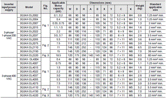
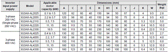
AC Reactor 3G3AX-AL[][][][]
Connect the AC Reactor if the capacity of the power supply is much larger than that of the Inverter or the power factor is required to be improved.
| Inverter | DC reactor specifications | |||||||||
|---|---|---|---|---|---|---|---|---|---|---|
| Voltage class | Max. applicable motor capacity (kW) | Model | Heavy load: CT, Light load: VT mode | Max. appli-cable motor capacity (kW) | Rated input current (A) | Model | Induc-tance (mH) | Heat gene-ration (W) | Operating ambient temperature/ humidity | Location |
| 3-phase 200-V class | 0.1 | 3G3MX2- A2001-V1 | Heavy load | 0.1 | 1.0 | 3G3AX- AL2025 | 2.8 | 12 | -10 to 50°C 20% to 90% | At an altitude of 1,000 m max.; indoors (without corrosive gases or dust) |
| Light load | 0.2 | 1.2 | ||||||||
| 0.2 | 3G3MX2- A2002-V1 | Heavy load | 0.2 | 1.6 | ||||||
| Light load | 0.4 | 1.9 | ||||||||
| 0.4 | 3G3MX2- A2004-V1 | Heavy load | 0.4 | 3.3 | ||||||
| Light load | 0.75 | 3.9 | ||||||||
| 0.75 | 3G3MX2- A2007-V1 | Heavy load | 0.75 | 6.0 | ||||||
| Light load | 1.1 | 7.2 | ||||||||
| 1.5 | 3G3MX2- A2015-V1 | Heavy load | 1.5 | 9.0 | ||||||
| Light load | 2.2 | 10.8 | 3G3AX- AL2055 | 0.88 | 25 | |||||
| 2.2 | 3G3MX2- A2022-V1 | Heavy load | 2.2 | 12.7 | ||||||
| Light load | 3.0 | 13.9 | ||||||||
| 3.7 | 3G3MX2- A2037-V1 | Heavy load | 3.7 | 20.5 | 3G3AX- AL2110 | 0.35 | 50 | |||
| Light load | 5.5 | 23.0 | ||||||||
| 5.5 | 3G3MX2- A2055-V1 | Heavy load | 5.5 | 30.8 | ||||||
| Light load | 7.5 | 37.0 | ||||||||
| 7.5 | 3G3MX2- A2075-V1 | Heavy load | 7.5 | 39.6 | 3G3AX- AL2220 | 0.18 | 50 | |||
| Light load | 11 | 48.0 | ||||||||
| 11 | 3G3MX2- A2110-V1 | Heavy load | 11 | 57.1 | ||||||
| Light load | 15 | 68.0 | ||||||||
| 15 | 3G3MX2- A2150-V1 | Heavy load | 15 | 62.6 | ||||||
| Light load | 18.5 | 72.0 | 3G3AX- AL2330 | 0.09 | 85 | |||||
| Single- phase 200-V Class | 0.1 | 3G3MX2- AB001-V1 | Heavy load | 0.1 | 1.3 | 3G3AX- AL2025 | 2.8 | 12 | -10 to 50°C 20% to 90% | At an altitude of 1,000 m max.; indoors (without corrosive gases or dust) |
| Light load | 0.2 | 2.0 | ||||||||
| 0.2 | 3G3MX2- AB002-V1 | Heavy load | 0.2 | 3.0 | ||||||
| Light load | 0.4 | 3.6 | ||||||||
| 0.4 | 3G3MX2- AB004-V1 | Heavy load | 0.4 | 6.3 | ||||||
| Light load | 0.55 | 7.3 | ||||||||
| 0.75 | 3G3MX2- AB007-V1 | Heavy load | 0.75 | 11.5 | 3G3AX- AL2055 | 0.88 | 25 | |||
| Light load | 1.1 | 13.8 | ||||||||
| 1.5 | 3G3MX2- AB015-V1 | Heavy load | 1.5 | 16.8 | ||||||
| Light load | 2.2 | 20.2 | 3G3AX- AL2110 | 0.35 | 50 | |||||
| 2.2 | 3G3MX2- AB022-V1 | Heavy load | 2.2 | 22.0 | ||||||
| Light load | 3.0 | 24.0 | ||||||||
| 3-phase 400-V class | 0.4 | 3G3MX2- A4004-V1 | Heavy load | 0.4 | 1.8 | 3G3AX- AL4025 | 7.7 | 12 | -10 to 50°C 20% to 90% | At an altitude of 1,000 m max.; indoors (without corrosive gases or dust) |
| Light load | 0.75 | 2.1 | ||||||||
| 0.75 | 3G3MX2- A4007-V1 | Heavy load | 0.75 | 3.6 | ||||||
| Light load | 1.5 | 4.3 | ||||||||
| 1.5 | 3G3MX2- A4015-V1 | Heavy load | 1.5 | 5.2 | ||||||
| Light load | 2.2 | 5.9 | ||||||||
| 2.2 | 3G3MX2- A4022-V1 | Heavy load | 2.2 | 6.5 | 3G3AX- AL4055 | 3.5 | 25 | |||
| Light load | 3.0 | 8.1 | ||||||||
| 3.0 | 3G3MX2- A4030-V1 | Heavy load | 3.0 | 7.7 | ||||||
| Light load | 4.0 | 9.4 | ||||||||
| 4.0 | 3G3MX2- A4040-V1 | Heavy load | 4.0 | 11.0 | 3G3AX- AL4110 | 1.3 | 50 | |||
| Light load | 5.5 | 13.3 | ||||||||
| 5.5 | 3G3MX2- A4055-V1 | Heavy load | 5.5 | 16.9 | ||||||
| Light load | 7.5 | 20.0 | ||||||||
| 7.5 | 3G3MX2- A4075-V1 | Heavy load | 7.5 | 18.8 | ||||||
| Light load | 11 | 24.0 | 3G3AX- AL4220 | 0.74 | 60 | |||||
| 11 | 3G3MX2- A4110-V1 | Heavy load | 11 | 29.4 | ||||||
| Light load | 15 | 38.0 | 3G3AX- AL4330 | 0.36 | 90 | |||||
| 15 | 3G3MX2- A4150-V1 | Heavy load | 15 | 35.9 | ||||||
| Light load | 18.5 | 44.0 | ||||||||
last update: August 1, 2018
OMRON 3G3MX2-V1 catalog
3G3MX2-V1 Multi-function Compact Inverter/Catalog- Catalog
- Manual
- CAD
English
Global Edition
| Catalog Name | Catalog Number [size] | Last Update | |
|---|---|---|---|
| | I920-E1-02 [6879KB] | Dec 06, 201820181206 | 3G3MX2-V1 Catalog |
OMRON 3G3MX2-V1 lineup
3G3MX2-V1 Multi-function Compact Inverter/Lineuplast update: December 6, 2018
Interpreting Model Numbers
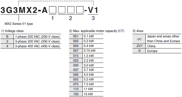
3G3MX2 Inverter Models
Note: Inverters with model numbers ending in "-V1" are designed to be used in areas other than China and Europe.
Refer to the above "Interpreting Model Numbers" for the model numbers for China and Europe.
| Rated voltage | Enclosure ratings | Max. applicable motor capacity | Model | |
|---|---|---|---|---|
| CT: Heavy load | VT: Light load | |||
| 3-phase 200 VAC | IP20 | 0.1 kW | 0.2 kW | 3G3MX2-A2001-V1 |
| 0.2 kW | 0.4 kW | 3G3MX2-A2002-V1 | ||
| 0.4 kW | 0.75 kW | 3G3MX2-A2004-V1 | ||
| 0.75 kW | 1.1 kW | 3G3MX2-A2007-V1 | ||
| 1.5 kW | 2.2 kW | 3G3MX2-A2015-V1 | ||
| 2.2 kW | 3.0 kW | 3G3MX2-A2022-V1 | ||
| 3.7 kW | 5.5 kW | 3G3MX2-A2037-V1 | ||
| 5.5 kW | 7.5 kW | 3G3MX2-A2055-V1 | ||
| 7.5 kW | 11 kW | 3G3MX2-A2075-V1 | ||
| 11 kW | 15 kW | 3G3MX2-A2110-V1 | ||
| 15 kW | 18.5 kW | 3G3MX2-A2150-V1 | ||
| 3-phase 400 VAC | IP20 | 0.4 kW | 0.75 kW | 3G3MX2-A4004-V1 |
| 0.75 kW | 1.5 kW | 3G3MX2-A4007-V1 | ||
| 1.5 kW | 2.2 kW | 3G3MX2-A4015-V1 | ||
| 2.2 kW | 3.0 kW | 3G3MX2-A4022-V1 | ||
| 3.0 kW | 4.0 kW | 3G3MX2-A4030-V1 | ||
| 4.0 kW | 5.5 kW | 3G3MX2-A4040-V1 | ||
| 5.5 kW | 7.5 kW | 3G3MX2-A4055-V1 | ||
| 7.5 kW | 11 kW | 3G3MX2-A4075-V1 | ||
| 11 kW | 15 kW | 3G3MX2-A4110-V1 | ||
| 15 kW | 18.5 kW | 3G3MX2-A4150-V1 | ||
| 1-phase 200 VAC | IP20 | 0.1 kW | 0.2 kW | 3G3MX2-AB001-V1 |
| 0.2 kW | 0.4 kW | 3G3MX2-AB002-V1 | ||
| 0.4 kW | 0.55 kW | 3G3MX2-AB004-V1 | ||
| 0.75 kW | 1.1 kW | 3G3MX2-AB007-V1 | ||
| 1.5 kW | 2.2 kW | 3G3MX2-AB015-V1 | ||
| 2.2 kW | 3.0 kW | 3G3MX2-AB022-V1 | ||
Communication Unit
| Name | Model |
|---|---|
| EtherCAT Communication Unit | 3G3AX-MX2-ECT |
| CompoNet Communication Unit | 3G3AX-MX2-CRT-E |
| DeviceNet Communication Unit | 3G3AX-MX2-DRT-E |
Related Options
| Name | Specifications | Model | |
|---|---|---|---|
| Regenerative Braking Units | 3-phase 200 VAC | General purpose with Braking resistor | 3G3AX-RBU21 |
| High Regeneration purpose with Braking resistor | 3G3AX-RBU22 | ||
| 3-phase 400 VAC | General purpose with Braking resistor | 3G3AX-RBU41 | |
| Braking Resistor | Compact type | Resistor 120 W, 180 Ω | 3G3AX-RBA1201 |
| Resistor 120 W, 100 Ω | 3G3AX-RBA1202 | ||
| Resistor 120 W, 5 Ω | 3G3AX-RBA1203 | ||
| Resistor 120 W, 35 Ω | 3G3AX-RBA1204 | ||
| Standard type | Resistor 200 W, 180 Ω | 3G3AX-RBB2001 | |
| Resistor 200 W, 100 Ω | 3G3AX-RBB2002 | ||
| Resistor 300 W, 50 Ω | 3G3AX-RBB3001 | ||
| Resistor 400 W, 35 Ω | 3G3AX-RBB4001 | ||
| Medium capacity type | Resistor 400 W, 50 Ω | 3G3AX-RBC4001 | |
| Resistor 600 W, 35 Ω | 3G3AX-RBC6001 | ||
| Resistor 1200 W, 17 Ω | 3G3AX-RBC12001 | ||
Regenerative Braking Unit and Braking Resistor Combination
| Inverter | Usage conditions | Regenerative braking unit | Braking resistor | Con- nec- tion con- figu- ra- tion | Restrictions | ||||||
|---|---|---|---|---|---|---|---|---|---|---|---|
| Volt- age | Max. appli- cable motor ca- pacity (kW) | Model | %ED *1 (%) | Ap- proxi- mate braking torque (% *2) | Model | Num- ber of units | Model | Num- ber of units | Allowa- ble contin- uous braking time (s) | Min. con- nect- able resis- tance (Ω) | |
| 200-V Class | 0.1 | 3G3MX2- A2001-V1 3G3MX2- AB001-V1 | 3.0% | 220% | Built-in Inverter | 3G3AX-RBA1201 | 1 | 1 | 20 | 100 | |
| 10.0% | 220% | 3G3AX-RBB2001 | 1 | 1 | 30 | 100 | |||||
| 0.2 | 3G3MX2- A2002-V1 3G3MX2- AB002-V1 | 3.0% | 220% | Built-in Inverter | 3G3AX-RBA1201 | 1 | 1 | 20 | 100 | ||
| 10.0% | 220% | 3G3AX-RBB2001 | 1 | 1 | 30 | 100 | |||||
| 0.4 | 3G3MX2- A2004-V1 3G3MX2- AB004-V1 | 3.0% | 220% | Built-in Inverter | 3G3AX-RBA1201 | 1 | 1 | 20 | 100 | ||
| 10.0% | 220% | 3G3AX-RBB2001 | 1 | 1 | 30 | 100 | |||||
| 0.75 | 3G3MX2- A2007-V1 3G3MX2- AB007-V1 | 3.0% | 120% | Built-in Inverter | 3G3AX-RBA1201 | 1 | 1 | 20 | 50 | ||
| 10.0% | 120% | 3G3AX-RBB2001 | 1 | 1 | 30 | 50 | |||||
| 1.5 | 3G3MX2- A2015-V1 3G3MX2- AB015-V1 | 2.5% | 110% | Built-in Inverter | 3G3AX-RBA1202 | 1 | 1 | 12 | 50 | ||
| 10.0% | 215% | 3G3AX-RBC4001 | 1 | 1 | 10 | 50 | |||||
| 2.2 | 3G3MX2- A2022-V1 3G3MX2- AB022-V1 | 3.0% | 150% | Built-in Inverter | 3G3AX-RBB3001 | 1 | 1 | 30 | 35 | ||
| 10.0% | 150% | 3G3AX-RBC4001 | 1 | 1 | 10 | 35 | |||||
| 3.7 | 3G3MX2- A2037-V1 | 3.0% | 125% | Built-in Inverter | 3G3AX-RBB4001 | 1 | 1 | 20 | 35 | ||
| 10.0% | 125% | 3G3AX-RBC6001 | 1 | 1 | 10 | 35 | |||||
| 5.5 | 3G3MX2- A2055-V1 | 3.0% | 120% | Built-in Inverter | 3G3AX-RBB3001 | 2 | 2 | 30 | 20 | ||
| 10.0% | 120% | 3G3AX-RBC4001 | 2 | 2 | 10 | 20 | |||||
| 7.5 | 3G3MX2- A2075-V1 | 3.0% | 125% | Built-in Inverter | 3G3AX-RBB4001 | 2 | 2 | 20 | 17 | ||
| 10.0% | 125% | 3G3AX-RBC6001 | 2 | 2 | 10 | 17 | |||||
| 11 | 3G3MX2- A2110-V1 | 3.0% | 90% | Built-in Inverter | 3G3AX-RBC12001 | 1 | 1 | 10 | 17 | ||
| 10.0% | 90% | 3G3AX-RBC12001 | 1 | 1 | 10 | 17 | |||||
| 10.0% | 125% | 3G3AX- RBU23 *3 | 1 | 3G3AX-RBC6001 | 3 | 14 | 10 | 4 | |||
| 15 | 3G3MX2- A2150-V1 | 3.0% | 110% | Built-in Inverter | 3G3AX-RBB3001 | 5 | 7 | 30 | 10 | ||
| 10.0% | 110% | 3G3AX-RBC4001 | 5 | 7 | 10 | 10 | |||||
| 400-V Class | 0.4 | 3G3MX2- A4004-V1 | 3.0% | 220% | Built-in Inverter | 3G3AX-RBA1201 | 2 | 3 | 20 | 180 | |
| 10.0% | 220% | 3G3AX-RBB2001 | 2 | 3 | 30 | 180 | |||||
| 0.75 | 3G3MX2- A4007-V1 | 3.0% | 220% | Built-in Inverter | 3G3AX-RBA1201 | 2 | 3 | 20 | 180 | ||
| 10.0% | 220% | 3G3AX-RBB2001 | 2 | 3 | 30 | 180 | |||||
| 1.5 | 3G3MX2- A4015-V1 | 3.0% | 120% | Built-in Inverter | 3G3AX-RBA1201 | 2 | 3 | 20 | 180 | ||
| 10.0% | 120% | 3G3AX-RBB2001 | 2 | 3 | 30 | 180 | |||||
| 2.2 | 3G3MX2- A4022-V1 | 2.5% | 150% | Built-in Inverter | 3G3AX-RBA1202 | 2 | 3 | 12 | 100 | ||
| 10.0% | 220% | 3G3AX-RBC4001 | 2 | 3 | 10 | 100 | |||||
| 3.0 | 3G3MX2- A4030-V1 | 2.5% | 110% | Built-in Inverter | 3G3AX-RBA1202 | 2 | 3 | 12 | 100 | ||
| 10.0% | 215% | 3G3AX-RBC4001 | 2 | 3 | 10 | 100 | |||||
| 4.0 | 3G3MX2- A4040-V1 | 3.0% | 165% | Built-in Inverter | 3G3AX-RBB3001 | 2 | 3 | 30 | 100 | ||
| 10.0% | 165% | 3G3AX-RBC4001 | 2 | 3 | 10 | 100 | |||||
| 5.5 | 3G3MX2- A4055-V1 | 3.0% | 120% | Built-in Inverter | 3G3AX-RBB3001 | 2 | 3 | 30 | 70 | ||
| 10.0% | 120% | 3G3AX-RBC4001 | 2 | 3 | 10 | 70 | |||||
| 7.5 | 3G3MX2- A4075-V1 | 3.0% | 125% | Built-in Inverter | 3G3AX-RBB4001 | 2 | 3 | 20 | 70 | ||
| 10.0% | 125% | 3G3AX-RBC6001 | 2 | 3 | 10 | 70 | |||||
| 11 | 3G3MX2- A4110-V1 | 3.0% | 85% | Built-in Inverter | 3G3AX-RBB4001 | 2 | 3 | 20 | 70 | ||
| 10.0% | 85% | 3G3AX-RBC6001 | 2 | 3 | 10 | 70 | |||||
| 10.0% | 120% | 3G3AX- RBU41 *3 | 1 | 3G3AX-RBC4001 | 4 | 15 | 10 | 34 | |||
| 15 | 3G3MX2- A4150-V1 | 3.0% | 125% | Built-in Inverter | 3G3AX-RBB4001 | 4 | 5 | 20 | 35 | ||
| 10.0% | 125% | 3G3AX-RBC6001 | 4 | 5 | 10 | 35 | |||||
*1 %ED shows the ratio that can be used for braking (deceleration time) among operating time of one task period.
*2 Approximate breaking torque is shown in % of rating torque of the motor (100%).
*3 Please remove the built-in resistor.
| Name | Specifications of Inverter | Model | ||
|---|---|---|---|---|
| Voltage class | CT: Heavy load | VT: Light load | ||
| Radio Noise Filter | 3-phase 200 VAC | 0.1 kW | 0.2 kW | 3G3AX-ZCL2 |
| 0.2 kW | 0.4 kW | |||
| 0.4 kW | 0.75 kW | |||
| 0.75 kW | 1.1 kW | |||
| 1.5 kW | 2.2 kW | |||
| 2.2 kW | 3.0 kW | |||
| 3.7 kW | 5.5 kW | 3G3AX-ZCL1 (3G3AX-ZCL2) | ||
| 5.5 kW | 7.5 kW | |||
| 7.5 kW | 11 kW | 3G3AX-ZCL1 | ||
| 11 kW | 15 kW | |||
| 15 kW | 18.5 kW | |||
| 1-phase 200 VAC | 0.1 kW | 0.2 kW | 3G3AX-ZCL2 | |
| 0.2 kW | 0.4 kW | |||
| 0.4 kW | 0.55 kW | |||
| 0.75 kW | 1.1 kW | |||
| 1.5 kW | 2.2 kW | |||
| 2.2 kW | 3.0 kW | |||
| 3-phase 400 VAC | 0.4 kW | 0.75 kW | 3G3AX-ZCL2 (3G3AX-ZCL1) | |
| 0.75 kW | 1.5 kW | |||
| 1.5 kW | 2.2 kW | |||
| 2.2 kW | 3.0 kW | |||
| 3.0 kW | 4.0 kW | |||
| 4.0 kW | 5.5 kW | |||
| 5.5 kW | 7.5 kW | |||
| 7.5 kW | 11 kW | 3G3AX-ZCL1 | ||
| 11 kW | 15 kW | |||
| 15 kW | 18.5 kW | |||
| Input Noise Filter | 3-phase 200 VAC | 0.1 kW | 0.2 kW | 3G3AX-NFI21 |
| 0.2 kW | 0.4 kW | |||
| 0.4 kW | 0.75 kW | |||
| 0.75 kW | 1.1 kW | 3G3AX-NFI22 | ||
| 1.5 kW | 2.2 kW | 3G3AX-NFI23 | ||
| 2.2 kW | 3.0 kW | |||
| 3.7 kW | 5.5 kW | 3G3AX-NFI24 | ||
| 5.5 kW | 7.5 kW | 3G3AX-NFI25 | ||
| 7.5 kW | 11 kW | 3G3AX-NFI26 | ||
| 11 kW | 15 kW | 3G3AX-NFI27 | ||
| 15 kW | 18.5 kW | 3G3AX-NFI28 | ||
| 1-phase 200 VAC | 0.1 kW | 0.2 kW | 3G3AX-NFI21 | |
| 0.2 kW | 0.4 kW | |||
| 0.4 kW | 0.55 kW | 3G3AX-NFI22 | ||
| 0.75 kW | 1.1 kW | 3G3AX-NFI23 | ||
| 1.5 kW | 2.2 kW | 3G3AX-NFI23 * | ||
| 2.2 kW | 3.0 kW | 3G3AX-NFI24 | ||
| 3-phase 400 VAC | 0.4 kW | 0.75 kW | 3G3AX-NFI41 | |
| 0.75 kW | 1.5 kW | |||
| 1.5 kW | 2.2 kW | |||
| 2.2 kW | 3.0 kW | 3G3AX-NFI42 | ||
| 3.0 kW | 4.0 kW | |||
| 4.0 kW | 5.5 kW | 3G3AX-NFI43 | ||
| 5.5 kW | 7.5 kW | |||
| 7.5 kW | 11 kW | 3G3AX-NFI44 | ||
| 11 kW | 15 kW | 3G3AX-NFI45 | ||
| 15 kW | 18.5 kW | 3G3AX-NFI46 | ||
| Output Noise Filter | 3-phase 200 VAC | 0.1 kW | 0.2 kW | 3G3AX-NFO01 |
| 0.2 kW | 0.4 kW | |||
| 0.4 kW | 0.75 kW | |||
| 0.75 kW | 1.1 kW | 3G3AX-NFO02 | ||
| 1.5 kW | 2.2 kW | |||
| 2.2 kW | 3.0 kW | 3G3AX-NFO03 | ||
| 3.7 kW | 5.5 kW | |||
| 5.5 kW | 7.5 kW | 3G3AX-NFO04 | ||
| 7.5 kW | 11 kW | |||
| 11 kW | 15 kW | 3G3AX-NFO05 | ||
| 1-phase 200 VAC | 0.1 kW | 0.2 kW | 3G3AX-NFO01 | |
| 0.2 kW | 0.4 kW | |||
| 0.4 kW | 0.55 kW | 3G3AX-NFO02 | ||
| 0.75 kW | 1.1 kW | |||
| 1.5 kW | 2.2 kW | 3G3AX-NFO03 | ||
| 2.2 kW | 3.0 kW | |||
| 3-phase 400 VAC | 0.4 kW | 0.75 kW | 3G3AX-NFO01 | |
| 0.75 kW | 1.5 kW | |||
| 1.5 kW | 2.2 kW | 3G3AX-NFO02 | ||
| 2.2 kW | 3.0 kW | |||
| 3.0 kW | 4.0 kW | |||
| 4.0 kW | 5.5 kW | 3G3AX-NFO03 | ||
| 5.5 kW | 7.5 kW | |||
| 7.5 kW | 11 kW | |||
| 11 kW | 15 kW | 3G3AX-NFO04 | ||
| 15 kW | 18.5 kW | |||
| DC Reactor | 3-phase 200 VAC | 0.1 kW | 0.2 kW | 3G3AX-DL2002 |
| 0.2 kW | 0.4 kW | 3G3AX-DL2004 | ||
| 0.4 kW | 0.75 kW | 3G3AX-DL2007 | ||
| 0.75 kW | 1.1 kW | 3G3AX-DL2015 | ||
| 1.5 kW | 2.2 kW | 3G3AX-DL2022 | ||
| 2.2 kW | 3.0 kW | 3G3AX-DL2037 | ||
| 3.7 kW | 5.5 kW | 3G3AX-DL2055 | ||
| 5.5 kW | 7.5 kW | 3G3AX-DL2075 | ||
| 7.5 kW | 11 kW | 3G3AX-DL2110 | ||
| 11 kW | 15 kW | 3G3AX-DL2150 | ||
| 15 kW | 18.5 kW | 3G3AX-DL2220 | ||
| 1-phase 200 VAC | 0.1 kW | 0.2 kW | 3G3AX-DL2002 | |
| 0.2 kW | 0.4 kW | 3G3AX-DL2004 | ||
| 0.4 kW | 0.55 kW | 3G3AX-DL2007 | ||
| 0.75 kW | 1.1 kW | 3G3AX-DL2015 | ||
| 1.5 kW | 2.2 kW | 3G3AX-DL2022 | ||
| 2.2 kW | 3.0 kW | 3G3AX-DL2037 | ||
| 3-phase 400 VAC | 0.4 kW | 0.75 kW | 3G3AX-DL4007 | |
| 0.75 kW | 1.5 kW | 3G3AX-DL4015 * | ||
| 1.5 kW | 2.2 kW | 3G3AX-DL4022 | ||
| 2.2 kW | 3.0 kW | 3G3AX-DL4037 | ||
| 3.0 kW | 4.0 kW | |||
| 4.0 kW | 5.5 kW | 3G3AX-DL4055 | ||
| 5.5 kW | 7.5 kW | 3G3AX-DL4075 * | ||
| 7.5 kW | 11 kW | 3G3AX-DL4110 * | ||
| 11 kW | 15 kW | 3G3AX-DL4150 | ||
| 15 kW | 18.5 kW | 3G3AX-DL4220 | ||
| AC Reactor | 3-phase 200 VAC | 0.1 kW | 0.2 kW | 3G3AX-AL2025 |
| 0.2 kW | 0.4 kW | |||
| 0.4 kW | 0.75 kW | |||
| 0.75 kW | 1.1 kW | |||
| 1.5 kW | 2.2 kW | 3G3AX-AL2055 | ||
| 2.2 kW | 3.0 kW | |||
| 3.7 kW | 5.5 kW | 3G3AX-AL2110 | ||
| 5.5 kW | 7.5 kW | 3G3AX-AL2110 * | ||
| 7.5 kW | 11 kW | 3G3AX-AL2220 | ||
| 11 kW | 15 kW | 3G3AX-AL2220 * | ||
| 15 kW | 18.5 kW | 3G3AX-AL2330 | ||
| 1-phase 200 VAC | 0.1 kW | 0.2 kW | 3G3AX-AL2025 | |
| 0.2 kW | 0.4 kW | |||
| 0.4 kW | 0.55 kW | |||
| 0.75 kW | 1.1 kW | |||
| 1.5 kW | 2.2 kW | 3G3AX-AL2055 * | ||
| 2.2 kW | 3.0 kW | 3G3AX-AL2110 | ||
| 3-phase 400 VAC | 0.4 kW | 0.75 kW | 3G3AX-AL4025 | |
| 0.75 kW | 1.5 kW | |||
| 1.5 kW | 2.2 kW | 3G3AX-AL4055 | ||
| 2.2 kW | 3.0 kW | |||
| 3.0 kW | 4.0 kW | |||
| 4.0 kW | 5.5 kW | 3G3AX-AL4110 | ||
| 5.5 kW | 7.5 kW | 3G3AX-AL4110 * | ||
| 7.5 kW | 11 kW | 3G3AX-AL4220 | ||
| 11 kW | 15 kW | 3G3AX-AL4220 * | ||
| 15 kW | 18.5 kW | 3G3AX-AL4330 | ||
* Only the CT rating is supported.
Note: When using the Inverter for light load rating, select the model with one size larger capacity (rated current).
| Name | Cable length (m) | Model |
|---|---|---|
| Digital Operator | - | 3G3AX-OP01 |
| Connection cable | 1 m | 3G3AX-OPCN1 |
| 3 m | 3G3AX-OPCN3 |
Recommended EtherCAT Communications Cables
Use Straight STP (shielded twisted-pair) cable of category 5 or higher with double shielding (braiding and aluminum foil tape) for EtherCAT.
Cable with Connectors
| Item | Appearance | Recommended manufacturer | Cable length (m) *1 | Model |
|---|---|---|---|---|
| Cable with Connectors on Both Ends (RJ45/RJ45) Standard RJ45 plugs type *1 Wire Gauge and Number of Pairs: AWG26, 4-pair cable Cable Sheath material: LSZH *2 Cable color: Yellow *3 |  | OMRON | 0.3 | XS6W-6LSZH8SS30CM-Y |
| 0.5 | XS6W-6LSZH8SS50CM-Y | |||
| 1 | XS6W-6LSZH8SS100CM-Y | |||
| 2 | XS6W-6LSZH8SS200CM-Y | |||
| 3 | XS6W-6LSZH8SS300CM-Y | |||
| 5 | XS6W-6LSZH8SS500CM-Y | |||
| Cable with Connectors on Both Ends (RJ45/RJ45) Rugged RJ45 plugs type *1 Wire Gauge and Number of Pairs: AWG22, 2-pair cable Cable color: Light blue |  | OMRON | 0.3 | XS5W-T421-AMD-K |
| 0.5 | XS5W-T421-BMD-K | |||
| 1 | XS5W-T421-CMD-K | |||
| 2 | XS5W-T421-DMD-K | |||
| 5 | XS5W-T421-GMD-K | |||
| 10 | XS5W-T421-JMD-K | |||
| Cable with Connectors on Both Ends (M12 Straight/M12 Straight) Shield Strengthening Connector cable *4 M12/Smartclick Connectors Wire Gauge and Number of Pairs: AWG22, 2-pair cable Cable color: Black |  | OMRON | 0.5 | XS5W-T421-BM2-SS |
| 1 | XS5W-T421-CM2-SS | |||
| 2 | XS5W-T421-DM2-SS | |||
| 3 | XS5W-T421-EM2-SS | |||
| 5 | XS5W-T421-GM2-SS | |||
| 10 | XS5W-T421-JM2-SS | |||
| Cable with Connectors on Both Ends (M12 Straight/RJ45) Shield Strengthening Connector cable *4 M12/Smartclick Connectors Rugged RJ45 plugs type Wire Gauge and Number of Pairs: AWG22, 2-pair cable Cable color: Black |  | OMRON | 0.5 | XS5W-T421-BMC-SS |
| 1 | XS5W-T421-CMC-SS | |||
| 2 | XS5W-T421-DMC-SS | |||
| 3 | XS5W-T421-EMC-SS | |||
| 5 | XS5W-T421-GMC-SS | |||
| 10 | XS5W-T421-JMC-SS |
*1 Standard type cables length 0.2, 0.3, 0.5, 1, 1.5, 2, 3, 5, 7.5, 10, 15 and 20 m are available.
Rugged type cables length 0.3, 0.5, 1, 2, 3, 5, 10 and 15 m are available.
For details, refer to Cat.No.G019.
*2 The lineup features Low Smoke Zero Halogen cables for in-cabinet use and PUR cables for out-of-cabinet use.
Although the LSZH cable is single shielded, its communications and noise characteristics meet the standards.
*3 Cables colors are available in blue, yellow, or Green.
*4 For details, contact your OMRON representative.
Cables/Connectors
Wire Gauge and Number of Pairs: AWG24, 4-pair Cable
| Item | Appearance | Recommended manufacturer | Model |
|---|---|---|---|
| Cables | --- | Hitachi Metals, Ltd. | NETSTAR-C5E SAB 0.5 x 4P CP * |
| --- | Kuramo Electric Co. | KETH-SB * | |
| --- | SWCC Showa Cable Systems Co. | FAE-5004 * | |
| RJ45 Connectors | --- | Panduit Corporation | MPS588-C * |
* We recommend you to use above cable and connector together.
Wire Gauge and Number of Pairs: AWG22, 2-pair Cable
| Item | Appearance | Recommended manufacturer | Model |
|---|---|---|---|
| Cables | --- | Kuramo Electric Co. | KETH-PSB-OMR * |
| --- | JMACS Japan Co., Ltd. | PNET/B * | |
| RJ45 Assembly Connector |  | OMRON | XS6G-T421-1 * |
* We recommend you to use above cable and connector together.
Software
How to Select Required Support Software for Your Controller
The required Support Software depends on the Controller to connect. Please check the following table when purchasing the Support Software.
| Item | Omron PLC System | Omron Machine Automation Controller System |
|---|---|---|
| Controller | CS, CJ, CP, and other series | NJ/NX-series |
| Inverter | Inverter MX2-series V1 type Inverter MX2-series V1 type with EtherCAT Communication Unit (Applicable to the CJ series only.) Inverter MX2-series V1 type with CompoNet Communication Unit Inverter MX2-series V1 type with DeviceNet Communication Unit | Inverter MX2-series V1 type Inverter MX2-series V1 type with EtherCAT Communication Unit Inverter MX2-series V1 type with CompoNet Communication Unit Inverter MX2-series V1 type with DeviceNet Communication Unit |
| Software | FA Integrated Tool Package CX-One | Automation Software Sysmac Studio |
FA Integrated Tool Package CX-One
| Product name | Specifications | Model | Stand- ards | ||
|---|---|---|---|---|---|
| Number of licenses | Media | ||||
| FA Integrated Tool Package CX-One Ver.4.[] | The CX-One is a comprehensive software package that integrates Support Software for OMRON PLCs and components. CX-One runs on following OS. Windows XP (Service Pack 3 or higher, 32-bit version)/ Windows Vista (32-bit/64-bit version)/ Windows 7 (32-bit/64-bit version)/ Windows 8 (32-bit/64-bit version)/ Windows 8.1 (32-bit/64-bit version)/ Windows 10 (32-bit/64-bit version) CX-One Version.4.[] includes CX-Drive Ver.2.[]. For details, refer to the CX-One catalog (Cat. No. R134) | 1 license * | DVD | CXONE-AL01D-V4 | - |
* Multi licenses (3, 10, 30, or 50 licenses) and DVD media without licenses are also available for the CX-One.
Automation Software Sysmac Studio
Please purchase a DVD and required number of licenses the first time you purchase the Sysmac Studio. DVDs and licenses are available individually. Each model of licenses does not include any DVD.
| Product name | Specifications | Model | Stand- ards | ||
|---|---|---|---|---|---|
| Number of licenses | Media | ||||
| Sysmac Studio Standard Edition Ver.1.[][] | The Sysmac Studio is the software that provides an integrated environment for setting, programming, debugging and maintenance of machine automation controllers including the NJ/NX-series CPU Units, NY-series Industrial PC,EtherCAT Slave, and the HMI. Sysmac Studio runs on the following OS. Windows 7(32-bit/64-bit version)/ Windows 8 (32-bit/64-bitversion)/ Windows 8.1 (32-bit/64-bit version)/ Windows 10 (32-bit/64-bit version) The Sysmac Studio Standard Edition DVD includes Support Software to set up EtherNet/IP Units, DeviceNet slaves, Serial Communications Units, and Support Software for creating screens on HMIs (CX- Designer). For details, refer to your OMRON website. | - (Media only) | DVD | SYSMAC-SE200D | - |
| 1 license * | --- | SYSMAC-SE201L | - | ||
* Multi licenses are available for the Sysmac Studio (3, 10, 30, or 50 licenses).
last update: December 6, 2018
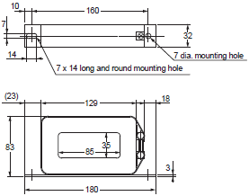
OMRON 3G3MX2-V1 dimension
3G3MX2-V1 Multi-function Compact Inverter/Dimensionslast update: August 1, 2018
(Unit: mm)
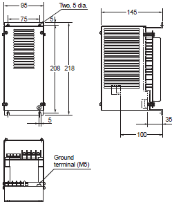
Inverter 3G3MX2
3G3MX2-AB001-V1
3G3MX2-AB002-V1
3G3MX2-AB004-V1
3G3MX2-A2001-V1
3G3MX2-A2002-V1
3G3MX2-A2004-V1
3G3MX2-A2007-V1
3G3MX2-AB007-V1
3G3MX2-AB015-V1
3G3MX2-AB022-V1
3G3MX2-A2015-V1
3G3MX2-A2022-V1
3G3MX2-A4004-V1
3G3MX2-A4007-V1
3G3MX2-A4015-V1
3G3MX2-A4022-V1
3G3MX2-A4030-V1
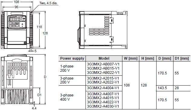
3G3MX2-A2037-V1
3G3MX2-A4040-V1
3G3MX2-A2055-V1
3G3MX2-A2075-V1
3G3MX2-A4055-V1
3G3MX2-A4075-V1
3G3MX2-A2110-V1
3G3MX2-A4110-V1
3G3MX2-A4150-V1
3G3MX2-A2150-V1
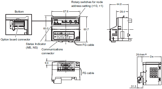
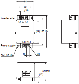
MX2-Series EtherCAT Communication Unit 3G3AX-MX2-ECT
3G3AX-MX2-ECT
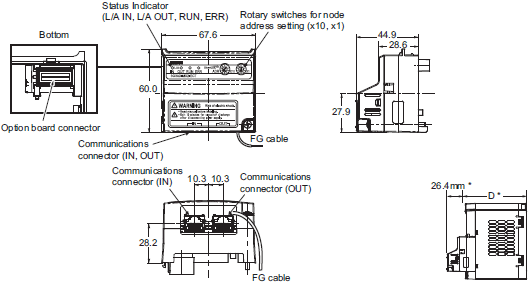
*After the EtherCAT Communication Unit is installed, dimension D of the inverter increases by 26.4 mm.
(Dimension D of the inverter varies depending on the capacity. Refer to the MX2-series V1 type USER'S MANUAL (Cat.
No.I585))
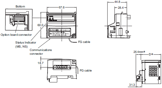
MX2-Series CompoNet Communication Unit 3G3AX-MX2-CRT-E
3G3AX-MX2-CRT-E
* After the CompoNet Communication Unit is installed, dimension D of the inverter increases by 26.4 mm.
(Dimension D of the inverter varies depending on the capacity. Refer to the MX2-series V1 type USER'S MANUAL (Cat.
No.I585))
MX2-Series DeviceNet Communication Unit 3G3AX-MX2-DRT-E
3G3AX-MX2-DRT-E
* After the DeviceNet Communication Unit is installed, dimension D of the inverter increases by 26.4 mm.
(Dimension D of the inverter varies depending on the capacity. Refer to the MX2-series V1 type USER'S MANUAL (Cat.
No.I585))
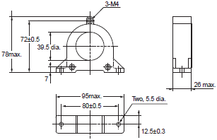
Options
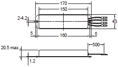
Regenerative Braking Unit 3G3AX-RBU[][]
3G3AX-RBU21/-RBU22/-RBU41
Braking Resistor 3G3AX-RBA/-RBB/-RBC[][][][]
3G3AX-RBA
3G3AX-RBB
3G3AX-RBC4001
3G3AX-RBC6001
3G3AX-RBC12001
Radio Noise Filter 3G3AX-ZCL[]
3G3AX-ZCL1
3G3AZ-ZCL2
Input Noise Filter 3G3AX-NFI[][]
3G3AX-NFI21
3G3AX-NFI22
3G3AX-NFI25/3G3AX-NFI26
3G3AX-NFI45/3G3AX-NFI46
3G3AX-NFI23/3G3AX-NFI24
3G3AX-NFI41/3G3AX-NFI42
3G3AX-NFI43/3G3AX-NFI44
3G3AX-NFI27/3G3AX-NFI28
Output Noise Filter 3G3AX-NFO[][]
3G3AX-NFO01
3G3AX-NFO02
3G3AX-NFO03/3G3AX-NFO04/3G3AX-NFO05

DC Reactor 3G3AX-DL[][][][]
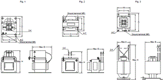
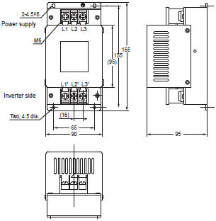
AC Reactor 3G3AX-AL[][][][]
3G3AX-AL2025
3G3AX-AL2055
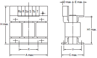
3G3AX-AL2110/3G3AX-AL2220
3G3AX-AL2330
3G3AX-AL4025/3G3AX-AL4055
3G3AX-AL4110

3G3AX-AL4220/3G3AX-AL4330
Digital Operator
3G3AX-OP01
last update: August 1, 2018
- NO. 3G3MX2-V1
- TYPE:Inverters Copyright Statement Copyright Statement
- DATE:2021-06-12
- Associated products:
R88M-K, R88D-KT G5-series AC Servomotors/Servo Drives with General-purpose Pulse Train or Analog Inputs/Features G6D-F4B / G3DZ-F4B Terminal Relay/Features