
OMRON TL-WSensors/ Proximity Sensors/Rectangular
OMRON TL-W Sensors
OMRON TL-W Dimensions
/Images/l_460-25-119031-198x198.jpglast update: September 24, 2012
• Only 6 mm thick yet provides a sensing distance of 3 mm (TL-W3MC1).
• Aluminum die-cast models also available.
last update: September 24, 2012
Purchase the OMRON Rectangular Please fill in the following
If you have just landed here, this product OMRON TL-W Sensors,Sensors is offered online by Tianin FLD Technical Co.,Ltd. This is an online store providing Sensors at wholesale prices for consumers. You can call us or send enquiry, we would give you the prices, packing,deliverty and more detailed information on the TL-W We cooperate with DHL,TNT,FEDEX,UPS,EMS,etc.They guarantee to meet your needs in terms of time and money,even if you need your OMRON TL-WSensors tomorrow morning (aka overnight or next day air) on your desk, 2, 3 days or more.Note to international customers, YES, we ship worldwide.
E2E Standard Proximity Sensor/Features
61F-03B / -04B Surge Killer Unit/Features
H3DT-G Star-delta Timer/Features
CJ1W-ETN21 CJ-series Ethernet Unit/Features
XW2Z (Standard-type) Connecting Cables for Connector-Terminal Block Conversion Units (Shielded)/F...
OMRON TL-W specification
TL-W Flat Inductive Proximity Sensor/Specificationslast update: June 1, 2017
DC 2-Wire Models
| Model | TL-W5MD[] | |
|---|---|---|
| Sensing distance | 5 mm ±10% | |
| Set distance | 0 to 4 mm | |
| Differential travel | 10% max. of sensing distance | |
| Detectable object | Ferrous metal (The sensing distance decreases with non-ferrous metal. Refer to Engineering Data on Data Sheet.) | |
| Standard sensing object | Iron, 18 × 18 × 1 mm | |
| Response frequency *1 | 500 Hz | |
| Power supply voltage (operating voltage range) | 12 to 24 VDC (10 to 30 VDC), ripple (p-p): 10% max. | |
| Leakage current | 0.8 mA max. | |
| Control output | Load current | 3 to 100 mA |
| Residual voltage | 3.3 V max. (under load current of 100 mA with cable length of 2 m) | |
| Indicators | D1 Models: Operation indicator (red), Setting indicator (green) D2 Models: Operation indicator (red) | |
| Operation mode (with sensing object approaching) | D1 Models: NO D2 Models: NC Refer to the timing charts under I/O Circuit Diagrams on Data Sheet for details. | |
| Protection circuits | Load short-circuit protection, Surge suppressor | |
| Ambient temperature range | Operating/Storage: -25 to 70°C (with no icing or condensation) | |
| Ambient humidity range | Operating/Storage: 35% to 95% (with no condensation) | |
| Temperature influence | ±10% max. of sensing distance at 23°C in the temperature range of -25 to 70°C | |
| Voltage influence | ±2.5% max. of sensing distance at rated voltage in the rated voltage ±15% range | |
| Insulation resistance | 50 MΩ min. (at 500 VDC) between current-carrying parts and case | |
| Dielectric strength | 1,000 VAC for 1 min between current-carrying parts and case | |
| Vibration resistance | Destruction: 10 to 55 Hz, 1.5-mm double amplitude for 2 hours each in X, Y, and Z directions | |
| Shock resistance | Destruction: 500 m/s2 3 times each in X, Y, and Z directions | |
| Degree of protection | IEC 60529 IP67, in-house standards: oil-resistant *2 | |
| Connection method | Pre-wired Models (Standard cable length: 2 m) | |
| Weight (packed state) | Approx. 80 g | |
| Materials | Case | Heat-resistant ABS |
| Sensing surface | ||
| Accessories | Instruction manual | |
*1. The response frequency is an average value.
Measurement conditions are as follows: standard sensing object, a distance of twice the standard sensing object,
and a set distance of half the sensing distance.
*2. For environments that require oil resistance, the upper limit of the ambient operating temperature range is 40°C.
DC 3-Wire Models
| Model | TL-W1R5MC1 TL-W1R5MB1 | TL-W3MC[] TL-W3MB[] | TL-W5MC[] TL-W5MB[] | TL-W5E1 TL-W5E2 TL-W5F1 TL-W5F2 | TL-W20ME1 TL-W20ME2 | |
|---|---|---|---|---|---|---|
| Sensing distance | 1.5 mm ±10% | 3 mm ±10% | 5 mm ±10% | 20 mm ±10% | ||
| Set distance | 0 to 1.2 mm | 0 to 2.4 mm | 0 to 4 mm | 0 to 16 mm | ||
| Differential travel | 10% max. of sensing distance | 1% to 15% of sensing distance | ||||
| Detectable object | Ferrous metal (The sensing distance decreases with non-ferrous metal. Refer to Engineering Data on Data Sheet.) | |||||
| Standard sensing object | Iron, 8 × 8 × 1 mm | Iron, 12 × 12 × 1 mm | Iron, 18 × 18 × 1 mm | Iron, 50 × 50 × 1 mm | ||
| Response frequency | 1 kHz min. | 600 Hz min. | 500 Hz min. | 300 Hz min. | 40 Hz min. | |
| Power supply voltage (operating voltage range) | 12 to 24 VDC (10 to 30 VDC), ripple (p-p): 10% max. | 12 to 24 VDC (10 to 30 VDC), ripple (p-p): 20% max. | 12 to 24 VDC (10 to 30 VDC), ripple (p-p): 10% max. | |||
| Current consumption | 15 mA max. at 24 VDC (no-load) | 10 mA max. at 24 VDC (no-load) | 15 mA max. at 24 VDC (no-load) | 8 mA at 12 VDC, 15 mA at 24 VDC | ||
| Control output | Load current | TL-W1R5MC1: NPN open collector 100 mA max. at 30 VDC max. TL-W1R5MC1/-W3MB[]: PNP open collector 100 mA max. at 30 VDC max. | TL-W5MC[]: NPN open collector 50 mA max. at 12 VDC (30 VDC max.) 100 mA max. at 24 VDC (30 VDC max.) TL-W5MB[]: PNP open collector 50 mA max. at 12 VDC (30 VDC max.) 100 mA max. at 24 VDC (30 VDC max.) | 200 mA | 100 mA max. at 12 VDC 200 mA max. at 24 VDC | |
| Residual voltage | 1 V max. (under load current of 100 mA with cable length of 2 m) | 2 V max. (under load current of 200 mA with cable length of 2 m) | 1 V max. (under load current of 200 mA with cable length of 2 m) | |||
| Indicators | Detection indicator (red) | |||||
| Operation mode (with sensing object approaching) | NO | B1/C1 Models: NO B2/C2 Models: NC | E1/F1 Models: NO E2/F2 Models: NC | |||
| Refer to the timing charts under I/O Circuit Diagrams on Data Sheet for details. | ||||||
| Protection circuits | Reverse polarity protection, Surge suppressor | |||||
| Ambient temperature range | Operating/Storage: -25 to 70°C (with no icing or condensation) * | |||||
| Ambient humidity range | Operating/Storage: 35% to 95% (with no condensation) | |||||
| Temperature influence | ±10% max. of sensing distance at 23°C in the temperature range of -25 to 70°C | |||||
| Voltage influence | ±2.5% max. of sensing distance at rated voltage in the rated voltage ±10% range | ±2.5% max. of sensing distance at rated voltage in the rated voltage ±20% range | ±2.5% max. of sensing distance at rated voltage in the rated voltage ±10% range | |||
| Insulation resistance | 50 MΩ min. (at 500 VDC) between current-carrying parts and case | |||||
| Dielectric strength | 1,000 VAC, 50/60 Hz for 1 minute between current-carrying parts and case | |||||
| Vibration resistance | Destruction: 10 to 55 Hz, 1.5-mm double amplitude for 2 hours each in X, Y, and Z directions | |||||
| Shock resistance | Destruction: 500 m/s2 3 times each in X, Y, and Z directions | Destruction: 500 m/s2 10 times each in X, Y, and Z directions | ||||
| Degree of protection | IEC 60529 IP67, in-house standards: oil-resistant * | |||||
| Connection method | Pre-wired Models (Standard cable length: 2 m) | |||||
| Weight (packed state) | Approx. 70 g | Approx. 80 g | Approx. 100 g | Approx. 210 g | ||
| Materials | Case | Heat-resistant ABS | Aluminum die-cast | Heat-resistant ABS | ||
| Sensing surface | Heat-resistant ABS | |||||
| Accessories | Mounting Bracket, Instruction manual | Instruction manual | ||||
* For environments that require oil resistance, the upper limit of the ambient operating temperature range is 40°C.
last update: June 1, 2017
OMRON TL-W catalog
TL-W Flat Inductive Proximity Sensor/Catalog- Catalog
- Manual
- CAD
English
Global Edition
| Catalog Name | Catalog Number [size] | Last Update | |
|---|---|---|---|
| | - [1180KB] | Jun 01, 201720170601 | TL-W Data Sheet |
OMRON TL-W dimension
TL-W Flat Inductive Proximity Sensor/Dimensionslast update: June 1, 2017
(Unit: mm)
Tolerance class IT16 applies to dimensions in this data sheet unless otherwise specified.
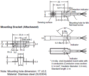
TL-W1R5MB1
TL-W1R5MC1
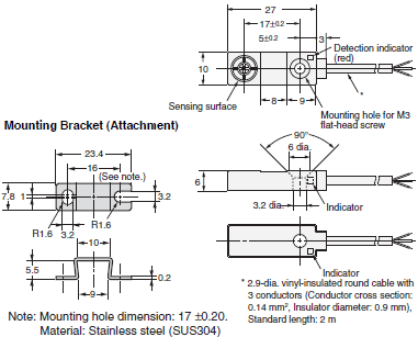
TL-W3MB[]
TL-W3MC[]
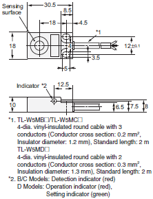
TL-W5MB[]
TL-W5MC[]
TL-W5MD[]
TL-W5E[]
TL-W5F[]
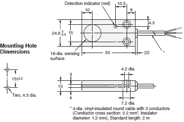
TL-W20ME[]
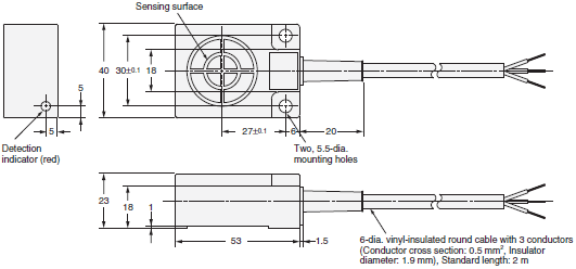
last update: June 1, 2017
OMRON TL-W lineup
TL-W Flat Inductive Proximity Sensor/Lineuplast update: June 1, 2017
Sensors
DC 2-Wire Models
| Appearance | Sensing distance | Model | |
|---|---|---|---|
| Operation mode | |||
| NO | NC | ||
Unshielded | 5 mm | TL-W5MD1 2M *1 *2 | TL-W5MD2 2M *2 |
DC 3-Wire Models
| Appearance | Sensing distance | Output configuration | Model | |
|---|---|---|---|---|
| Operation mode | ||||
| NO | NC | |||
Unshielded | 1.5 mm | NPN | TL-W1R5MC1 2M *1 *2 | --- |
| PNP | TL-W1R5MB1 2M | --- | ||
| 3 mm | NPN | TL-W3MC1 2M *1 *2 | TL-W3MC2 2M *1 *2 | |
| PNP | TL-W3MB1 2M *2 | TL-W3MB2 2M *2 | ||
| 5 mm | NPN | TL-W5MC1 2M *1 *2 | TL-W5MC2 2M | |
| PNP | TL-W5MB1 2M | TL-W5MB2 2M | ||
| 20 mm | NPN | TL-W20ME1 2M *1 | TL-W20ME2 2M *1 | |
Shielded | 5 mm | NPN | TL-W5E1 2M | TL-W5E2 2M |
| PNP | TL-W5F1 2M | TL-W5F2 2M | ||
*1. Models with a different frequency are also available to prevent mutual interference.
The model numbers are TL-W[]M[][]5 (e.g., TL-W5MD15).
*2. Models are also available with robotics (bend resistant) cables. Add “-R” to the model number.
(e.g., TL-W5MC1-R 2M)
last update: June 1, 2017
- NO. TL-W
- TYPE:Proximity Sensors Rectangular
 Copyright Statement
 - DATE:2021-06-08
- Associated products:
E2S Super-compact Proximity Sensor/Features TL-N / -Q Rectangular Standard Proximity Sensor/Features