
OMRON H3DT-GControl Components/ Timers/Analog Timers
OMRON H3DT-G Control Components
OMRON H3DT-G Dimensions
/Images/l_3489-25-257429-198x198.jpglast update: April 01, 2016
New Value For Control Panels
Control Panels: The Heart of Manufacturing Sites.
Evolution in control panels results in large evolution in production facilities.
And if control panel design, control panel manufacturing processes, and human interaction with them are innovated, control panel manufacturing becomes simpler and takes a leap forward.
OMRON will continue to achieve a control panel evolution and process innovation through many undertakings starting with the shared Value Design for Panel concept for the specifications of products used in control panels.

Our shared Value Design for Panel (herein after referred to as "Value Design") concept for the specifications of products used in control panels will create new value to our customer’s control panels.
Combining multiple products that share the Value Design concept will further increase the value provided to control panels.
Technology and Quality Developed over 80 Years of History
Now the H3DT Series of Timers Are Available with New Advanced Concepts
It's been 80 years since the production of OMRON's first product: an X-ray Timer.
They provide more value to the customer while leading control panels to a new stage.

The Top Class in Industry*1 for Low Power Consumption
Power consumption is low, which reduces the DC power supply load for the entire control panel.

Push-In Plus Terminal Blocks for Easy Wiring
Just Insert Wires: No Tools Required
Now you can use Push-In Plus terminal blocks to reduce the time and work involved in wiring.
Greatly Reduce Wiring Work with Push-In Plus Terminal Blocks

No Retightening Required

Tightening screws is necessary for screw terminal blocks, but with Push-In Plus terminal blocks, there is no need for retightening.
This reduces works for wirings, inspections, delivery (shipping), or maintenance.
Easy to Insert
OMRON’s Push-In Plus terminal blocks are as easy as inserting to an earphone jack. They help reduce the work load and improve wiring quality.
Held Firmly in Place
Even though less insertion force is required, the wires are held firmly in place. The advanced mechanism design technology and manufacturing technology produced a spring that ensures better workability and reliability.

Certified for Safety Standards of Major Countries
The Timers help to reduce the work involved in control panel design with certifications and compliance for various standards, including UL Listing.

last update: April 01, 2016
Purchase the OMRON Analog Timers Please fill in the following
If you have just landed here, this product OMRON H3DT-G Control Components,Control Components is offered online by Tianin FLD Technical Co.,Ltd. This is an online store providing Control Components at wholesale prices for consumers. You can call us or send enquiry, we would give you the prices, packing,deliverty and more detailed information on the H3DT-G We cooperate with DHL,TNT,FEDEX,UPS,EMS,etc.They guarantee to meet your needs in terms of time and money,even if you need your OMRON H3DT-GControl Components tomorrow morning (aka overnight or next day air) on your desk, 2, 3 days or more.Note to international customers, YES, we ship worldwide.
A4EG Enabling Grip Switch/Features
WS02-SGWC1 / CPLC1 FA Communications Software/Features
E3S-DB Transparent Object Detection Photoelectric Sensor/Features
E3Z-LT / LR / LL Compact Laser Photoelectric Sensor with Built-in Amplifier/Features
TL-W Flat Inductive Proximity Sensor/Features
OMRON H3DT-G lineup
H3DT-G Star-delta Timer/Lineuplast update: October 20, 2016
List of Models
| Operating modes | Supply voltage | Control output | H3DT-G | |
|---|---|---|---|---|
| Star-delta Timer | 24 to 240 VAC/DC | Contact outputs Delta circuit: SPDT, Star circuit: SPDT | Model | H3DT-G |
Model Structure
| Model | Terminal block | Operating/resetting method | Output type | Mounting method | Safety standards |
|---|---|---|---|---|---|
| H3DT-G | 8 terminals | Time-limit operation/ self-resetting | Time-limit (relay) Star circuit: SPDT Delta circuit: SPDT | DIN Track mounting | cULus (UL 508 CSA C22.2 No. 14) CCC LR DNV GL EN 61812-1 IEC 60664-1 4 kV/2 |
last update: October 20, 2016
OMRON H3DT-G catalog
H3DT-G Star-delta Timer/Catalog- Catalog
- CAD
English
Global Edition
| Catalog Name | Catalog Number [size] | Last Update | |
|---|---|---|---|
| | M090-E1-01 [9435KB] | Jul 12, 201720170712 | H3DT Data Sheet |
| | M091-E1-01 [2563KB] | Oct 11, 201620161011 | H3DT Catalog |
| | - [43KB] | Mar 12, 201820180312 | Recommended Replacement Periods and Periodic Replacement for Preventive Maintenance |
| | Y218-E1-03 [13592KB] | Oct 02, 201720171002 | Innovation in Control Panel Building |
OMRON H3DT-G dimension
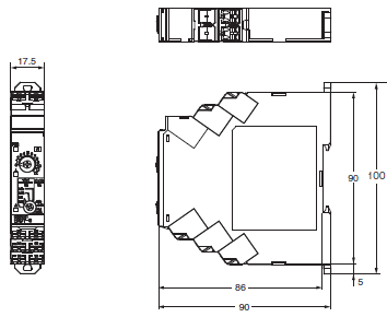
H3DT-G Star-delta Timer/Dimensionslast update: April 01, 2016
Timers
H3DT-G
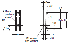
Track Mounting Products (Sold Separately)
DIN Track
PFP-100N
PFP-50N

DIN Track
PFP-100N2

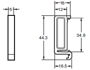
End Plate
PFP-M
Spacer
PFP-S
Note: 1. Order the above products in multiples of 10.
2. The Tracks conform to DIN standards.
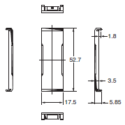
Options (Order Separately)
Front Cover
Y92A-D1A
last update: April 01, 2016
OMRON H3DT-G specification
H3DT-G Star-delta Timer/Specificationslast update: October 20, 2016
Time Ranges
| Time range setting | t1x1 | t1x10 |
|---|---|---|
| Star set time (t1) range | 1 to 12 s | 10 to 120 s |
| Star-Delta transfer time (t2) | Select from 0.05, 0.1, 0.25, or 0.5 s. | |
Ratings
| Power supply voltage *1 | 24 to 240 VAC/DC, 50/60 Hz *2 | |
|---|---|---|
| Allowable voltage fluctuation range | 85% to 110% of rated voltage | |
| Power reset | Minimum power-OFF time: 0.1 s | |
| Reset voltage | 10% of rated voltage | |
| Power consumption | H3DT-N2/-L2 | At 240 VAC: 1.9 VA max., at 240 VDC: 0.6 W max., at 24 VDC: 0.3 W max. |
| Rated Insulation Voltage | 250 V | |
| Control output | Contact output: 5 A at 250 VAC with resistive load (cosφ = 1), 5 A at 30 VDC with resistive load 0.15 A max at 125 VDC with resistive load, 0.1 A max at 125 VDC with L/R of 7 ms. The minimum applicable load is 10 mA at 5 VDC (P reference value). Contact materials: Ag-alloy (Recommended fuse: BLN5 (Littelfuse) or 0216005MXEP) | |
| Ambient operating temperature | -20 to 60°C (with no icing) | |
| Storage temperature | -40 to 70°C (with no icing) | |
| Surrounding air operating humidity | 25% to 85% | |
*1.When using a 24-VDC power supply voltage, there will be an inrush current of approximately 0.5 A.
Allow for this inrush current when turning ON and OFF the power supply to the Timer with device with a solid-state output,
such as a sensor.
*2. DC ripple: 20% max.
Characteristics
| Accuracy of operating time | ±1% of FS max. | |
|---|---|---|
| Setting error | ±10% of FS ±0.05 s max. | |
| Transfer time | Total error ± (25% of transfer time + 5 ms) max. | |
| Influence of voltage | ±0.5% of FS max. | |
| Influence of temperature | ±2% of FS max. | |
| Insulation resistance | 100 MΩ min. at 500 VDC | |
| Dielectric strength | Between charged metal part and operating section: 2,900 VAC 50/60 Hz for 1 min. Between control output terminals and operating circuit: 2,000 VAC 50/60 Hz for 1 min. Between contacts not located next to each other: 1,000 VAC 50/60 Hz for 1 min. | |
| Impulse withstand test voltage | 5 kV between power terminals, 7.4 kV between conductor terminal and operating section | |
| Noise immunity | Square-wave noise generated by noise simulator (pulse width: 100 ns/1 μs, 1-ns rise): ±1.5 kV | |
| Static immunity | Malfunction: 4 kV, Destruction: 8 kV | |
| Vibration resistance | Destruction | 0.75-mm single amplitude at 10 to 55 Hz for 2 h each in 3 directions |
| Malfunction | 0.5-mm single amplitude at 10 to 55 Hz for 10 min each in 3 directions | |
| Shock resistance | Destruction | 1,000 m/s2 3 times each in 6 directions |
| Malfunction | 100 m/s2 3 times each in 6 directions | |
| Life expectancy | Mechanical | 10 million operations min. (under no load at 1,800 operations/h) |
| Electrical | 100,000 operations min. (5 A at 250 VAC, resistive load at 360 operations/h) | |
| Degree of protection | IP30 (Terminal block: IP20) | |
| Weight | Approx. 100 g | |
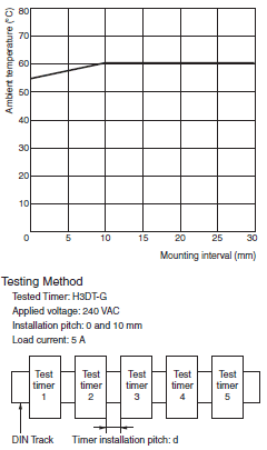
Relation between H3DT Ambient Temperature and Mounting Interval (Reference Values)
The relation between the ambient temperature and mounting interval is shown in the following graph.
If the Timer is used at 55°C or higher with a mounting interval that is smaller than that shown in the following diagram, the temperature inside the Timer will increase, reducing the life expectancy of internal parts.
Applicable standards
| Safety standards | cULus: UL 508/CSA C22.2 No. 14 EN 61812-1: Pollution degree 2, Overvoltage category III CCC: Pollution degree 2, Overvoltage category II, section GB 14048.5 LR: Category ENV1.2 DNV GL (Temperature B, Humidity B, Vibration A, EMC A, Enclosure A) |
|---|---|
| EMC | (EMI) EN 61812-1 Radiated Emissions: EN 55011 class B Emission AC Mains: EN 55011 class B Harmonic Current: EN 61000-3-2 Voltage Fluctuations and Flicker: EN 61000-3-3 (EMS) EN 61812-1 Immunity ESD: EN 61000-4-2 Immunity RF-interference: EN 61000-4-3 Immunity Burst: EN 61000-4-4 Immunity Surge: EN 61000-4-5 Immunity Conducted Disturbance: EN 61000-4-6 Immunity Voltage Dip/Interruption: EN 61000-4-11 |
I/O
| Input | None | |
|---|---|---|
| Output | Control output | The star output is turned OFF when the dial set value is reached and the delta output is turned ON after the preset transfer time elapses. |
last update: October 20, 2016
- NO. H3DT-G
- TYPE:Timers Analog Timers
 Copyright Statement
 - DATE:2021-06-11
- Associated products:
H3DT-F Twin Timer/Features H3DT-H Power OFF-delay Timer/Features