
OMRON F3SJ SeriesSafety Components/ Safety Light Curtains / Single-beam Safety Sensors/Safety Light Curtains
OMRON F3SJ Series Safety Components
OMRON F3SJ Series Dimensions
/Images/l_1581-25-118826-198x198.jpglast update: April 2, 2018
Implementation cost reduction with 1/2* the mounting time: Start with the "EASY type"
* Comparison with existing OMRON products.
The EASY type safety light curtain well is suited for straight forward on/off detection applications.
By carefully selecting the available functions, we have reduced man hours necessary for installation by approximately 1/2 when compared with existing OMRON models.
Reduced installation time means added savings to your project's budget, start with the EASY type.

Machine safety first, narrowed down to the simplest functions:
Upon detection of personnel, the machine stops. Simple yet very optimal.

1/2 the mounting time
Fixed response time makes calculation of the safety distance is easier.
Reduced wiring, one-touch brackets and easy-to-view alignment beams all add up to cost savings.
Additionally, with one fixed response time, it is know easier to calculate the safety distance.

Global Support
OMRON will support you through the our global network

Easy-to-view Diagnostics
These indicators enable you to intuitively know the status and cause of any error.
Allowing you faster installation while reducing machine down time.
Fits any site, equipped with muting functions and series connection: Use the "BASIC type"
In addition to the simple functions inherited from the EASY type, such as global support, easy-to-view indicators, the BASIC type includes series connection and simple muting functions . This enables the BASIC type to satisfy installations that require multiple safety light curtains.

Up to three sets-connected in series
It is possible to connect up to three sets of safety light curtains in series. These sensors can be placed in a U-shaped or L-shaped pattern with a single power line, thus requiring less wiring.

Instant visibility of process trouble during muting
The BASIC type includes a muting function which temporarily disables the safety light curtain when a workpiece passes through. In the event of any trouble occurring, the error can be instantly recognized from the pattern of the LED indicators, allowing for a fast solution.

Functions inherited from the EASY type
Simple functions such as universal power voltage specification, easy-to-view diagnostics, a fixed response time have been inherited from the EASY type, As a result, expect reduced work-hours at each stage of use, from design and installation to operation.
Multi-functional for special applications such as finger protection: the "ADVANCED" type
The detection capability supports finger protection through use of 9 mm resolution. The ADVANCED type is equipped with various functions such as blanking, muting and the programing of warning zones. All settings can be done via an easy to use software tool. This Tool simplifies installations that were previously complicated, again our way of reducing cost and increasing productivity.

Tool for setting parameters and checking the system status
With the ADVANCED type (F3SJ-A) “SD Manager”, all parameters can be set and the system status can be checked with a personal computer. Complex settings are now simple to configure

Detection capability supports finger-protection
Even if the distance from the hazard is short, we have prepared a lineup that includes safety light curtains with a detection capability of 14 mm.
Versatile muting function possible
Equipped with partial muting that disables only the beams where a workpiece passes through, and position detection muting that disables the beams while detecting the position of a machine or robot.

Partial muting

Position detection muting
The blanking function disables specific beams of the Safety Light Curtain
If a part of the mechanical equipment is within the detection zone of the Safety Light Curtain, the relevant beams can be disabled. This is possible not only with non-moving parts but also with moving parts.

Fixed blanking

Floating blanking
Setting up a warning zone to prevent unnecessary stoppage
Under normal use, if an intrusion occurs in the safety zone, the machine will stop immediately. However, use of a warning zone will only notify the operator that an intrusion has occurred. This can be used to prevent carelessness resulting in machine stoppage on the part of the operator.

Dividing the zone between series-connected sensors

A single sensor zone can also be divided
Providing ease-of-use and ease-of-mounting through ingenuity
Easy and fast mounting with one-touch brackets*
* Sold separately

[Patented]
OMRON has developed "one-touch" brackets which speed mounting to aluminum framing and reduce mounting time in half, when compared with existing models.
This unique design allows for smooth horizontal movement, beam alignment is easy.

Top and bottom blue LEDs enabling beam alignment

Simple positional alignment can be done using the blue LEDs at the top (TOP) and bottom (BTM) of the emitter and receiver. With the blue LEDs ON, you can see at a glance that the beams' positions are correctly aligned.

Towards a more usable and installable safety light curtain.
Laser pointer used to easily align the beams *

* Sold separately
Use of the laser pointer allows simple alignment of the beams especially across long distances.
This saves approximately 60% of installation time.


Easy-to-understand diagnostics

Light curtain status can be immediately determined as the LED will light to indicate the status or possible error.
Communication error (EASY/BASIC type)

Input error (BASIC type)

Industry First! Error indication while muting is in progress.

The days of searching through user manuals to find the cause of certain muting errors are long gone. Now these errors and their causes can be well understood.

Providing multiple functions to cope with the various safety requirements
"Simple wiring connector" used to reduce wiring work by more than 50%*

The connector can be used to easily connect between an emitter and a receiver, reducing the required wiring time by more than 50%.
Less wiring also reduces the width of the terminal block, saving valuable space in the control panel.
Note: The simple wiring connector can be used for F3SJ-A/B in auto reset mode only, not for F3SJ-E.
* Comparison with existing OMRON products.

Tool for setting parameters and checking the system status

"SD Manager" PC Setting Support Software (For F3SJ-A)

All parameters can be set and the system status can be checked with a personal computer. In addition to making it easy to monitor the beam alignment, the ambient incident light intensity can be displayed in bar graph form for an easy check of the system status.
The "SD Manager" PC Setting Support Software helps reduce the time required for installing and troubleshooting the Safety Light Curtain.
Beam alignment is easier.

The incident light level can be displayed in a bar graph for each beam.
The ambient incident light intensity can be checked.

The incident light level when the light emission of the Safety Light Curtain is stopped is displayed in a bar graph.
The error log can be displayed.

The cause of the errors and countermeasures are both displayed.
Added the ENVIRONMENT RESISTANT type (F3SJ-B[][][][]P25-02TS) to the E3SJ series.
The coolant-resistant structure supports use in a severe work environment


Protects the sensor unit from direct exposure to the coolant.
The aluminum frame and transparent plate protect the sensor unit from direct exposure to the coolant. The cover protects the sensor's detection surface from collision with a workpiece, etc.

Protects the sensor from entry of the coolant that runs around the sensor.
The coolant-resistant H-NBR sponge used inside the cover protects the sensor from entry of the coolant that runs around the sensor.
Note: The sensor may be affected depending on the type of the cutting oil. Check the oil type before use.
Achieving muting function without a controller

The muting function temporarily disables the light curtain when an object must pass through the detection zone, such as when supplying a workpiece to your equipment. In the past, this function required a dedicated muting controller, but now it is built into the F3SJ. To use the muting function, purchase the Muting Key Cap (for F3SJ-B: F39-CN10 and for F3SJ-A: F39-CN6) (sold separately). The muting function is enabled simply by replacing the Unit's cap with this Key Cap. In addition, a muting sensor that determines the muting timing, as well as a muting lamp that notices the muting status to other operators, should be connected to the F3SJ.
The muting time for the F3SJ-A can be set via the software tool.
Use example of a muting key cap for F3SJ-A
[Built-in muting function]
No controller required. Simply attach the Key Cap (sold separately) to the sensor.

Equipped with two muting functions

With F3SJ-A, the muting function temporarily disables the Safety Light Curtain when an object must pass through the detection zone, such as when supplying a workpiece to your equipment. "Partial muting," which further heightens the level of safety, and "position detection muting," which allows muting when the safety status can be determined by the position of a machine (such as a robot), have been newly added to the muting function.
Partial muting

Partial muting raises safety by muting only the beams of the Safety Light Curtain in the area where the workpiece passes through, while preventing muting in all other areas.
Position detection muting

This is used in applications where the workpiece is set in position each time by an operator, and then a turntable or positioning robot moves the workpiece to the area where the work is done. A limit switch or other means is used to detect when the robot is in a safe position, and muting is then applied.
last update: April 2, 2018
Purchase the OMRON Safety Light Curtains Please fill in the following
If you have just landed here, this product OMRON F3SJ Series Safety Components,Safety Components is offered online by Tianin FLD Technical Co.,Ltd. This is an online store providing Safety Components at wholesale prices for consumers. You can call us or send enquiry, we would give you the prices, packing,deliverty and more detailed information on the F3SJ Series We cooperate with DHL,TNT,FEDEX,UPS,EMS,etc.They guarantee to meet your needs in terms of time and money,even if you need your OMRON F3SJ SeriesSafety Components tomorrow morning (aka overnight or next day air) on your desk, 2, 3 days or more.Note to international customers, YES, we ship worldwide.
G7S-[]-E Relays with Forcibly Guided Contacts/Features
NX1P2 NX-series NX1P2 CPU Units/Features
E3S-R Transparent Object Detection Sensor/Features
E52 with Ferrule (Low-cost Models) Temperature Sensor with Ferrule (Low-cost Models)/Features
H5S Digital Time Switch/Features
OMRON F3SJ Series lineup
F3SJ Series Safety Light Curtain/Lineup F3SJ-E
 F3SJ-B
 F3SJ-A
last update: June 11, 2018
F3SJ-E
Main Units
Safety Light Curtain
| Application | Detection capability | Beam gap | Operating range | Protective height (mm) | Model | |
|---|---|---|---|---|---|---|
| PNP output | NPN output | |||||
| Hand protection | Dia. 25 mm | 20 mm | 0.2 to 7 m | 185 to 1,105 | F3SJ-E[][][][]P25 * | F3SJ-E[][][][]N25 |
Note: F3SJ-E uses a 3 m prewired discrete cable.
*1. For S-mark compatible model, the suffix "-S" is added to the model name.
(Example) F3SJ-E0185P25-S
Safety Light Curtain Model List
Please contact our sales representative.
F3SJ-E Series (20 mm pitch)
| Model | Number of beams | Protective height [mm] *2 | |
|---|---|---|---|
| PNP output *1 | NPN output | ||
| F3SJ-E0185P25 | F3SJ-E0185N25 | 8 | 185 |
| F3SJ-E0225P25 | F3SJ-E0225N25 | 10 | 225 |
| F3SJ-E0305P25 | F3SJ-E0305N25 | 14 | 305 |
| F3SJ-E0385P25 | F3SJ-E0385N25 | 18 | 385 |
| F3SJ-E0465P25 | F3SJ-E0465N25 | 22 | 465 |
| F3SJ-E0545P25 | F3SJ-E0545N25 | 26 | 545 |
| F3SJ-E0625P25 | F3SJ-E0625N25 | 30 | 625 |
| F3SJ-E0705P25 | F3SJ-E0705N25 | 34 | 705 |
| F3SJ-E0785P25 | F3SJ-E0785N25 | 38 | 785 |
| F3SJ-E0865P25 | F3SJ-E0865N25 | 42 | 865 |
| F3SJ-E0945P25 | F3SJ-E0945N25 | 46 | 945 |
| F3SJ-E1025P25 | F3SJ-E1025N25 | 50 | 1,025 |
| F3SJ-E1105P25 | F3SJ-E1105N25 | 54 | 1,105 |
*1. For S-mark compatible model, the suffix "-S" is added to the model name.
(Example) F3SJ-E0185P25-S
*2. Protective height (mm) = Total sensor length
Accessories (Sold separately)
Relays with Forcibly Guided Contacts
| Type | Appearance | Specifications | Model | Remarks |
|---|---|---|---|---|
| G7SA Relays with Forcibly Guided Contacts |  | Nodes: 4 Contact type: 2A2B Rated switch load: 250 VAC 6A, 30 VDC 6A | G7SA-2A2B | For details on other models or socket models, refer to the OMRON's website. |
| Nodes: 4 Contact type: 3NO+1NC Rated switch load: 250 VAC 6A, 30 VDC 6A | G7SA-3A1B | |||
| G7S-[]-E Relays with Forcibly Guided Contacts |  | Nodes: 6 Contact type: 4NO+2NC Rated switch load: 250 VAC 10 A, 30 VDC 10 A | G7S-4A2B-E | For details on other models or socket models, refer to the OMRON's website. |
| Nodes: 6 Contact type: 3NO+3NC Rated switch load: 250 VAC 10 A, 30 VDC 10 A | G7S-3A3B-E |
Laser Pointer
| Appearance | Output | Model |
|---|---|---|
 | Laser Pointer for F3SJ | F39-PTJ |
Spatter Protection Cover (2 covers per set, one for emitter and one for receiver) (10% Operating Range Attenuation)
| Appearance | Model |
|---|---|
 | F39-HB[][][][] * |
* The same 4-digit numbers as the protective heights ([][][][] in the light curtain model names) are substituted by in the
model names.
Protective Bar
| Appearance | Model | Remarks |
|---|---|---|
 | F39-PB[][][][] *1 | 2 Light Curtain brackets 4 mounting brackets 0 to 4 intermediate brackets for backside mounting (quantity required for the sensing width) 0 to 4 intermediate brackets for mounting to the sides (quantity required for the sensing width) |
| F39-PB[][][][]-S *1 *2 | 1 Light Curtain bracket 2 mounting brackets 0 to 2 intermediate brackets for backside mounting (quantity required for the sensing width) 0 to 2 intermediate brackets for mounting to the sides (quantity required for the sensing width) |
Note: The following are not provided with the Protective Bars.
• Safety Light Curtain
• Safety Light Curtain Top/Bottom Brackets
• Wall Mounting Screw Unit
*1. The same four digits indicating protective height that are used in the Sensor model number ([][][][]) are used in the
part of the Protector model number.
*2. Purchase the F39-PB[][][][] (which contains two sets of brackets) to use Protective Bars for both the Emitter and
Receiver.
Test rod (Sold separately)
| Diameter | Model |
|---|---|
| 14mm dia. | F39-TRD14 |
| 20mm dia. | F39-TRD20 |
| 25mm dia. | F39-TRD25 |
| 30mm dia. | F39-TRD30 |
Mirrors (12% Operating Range Attenuation)
| Appearance | Mirror material | Width (mm) | Thickness (mm) | Length L (mm) | Model | Remarks |
|---|---|---|---|---|---|---|
 | Glass mirror | 145 | 32 | 445 | F39-MLG0406 | 2 sets of cylinder mounting brackets and 4 screws are included. |
| 648 | F39-MLG0610 | |||||
| 749 | F39-MLG0711 | |||||
| 953 | F39-MLG0914 | |||||
| 1,105 | F39-MLG1067 | |||||
| 1,257 | F39-MLG1219 | |||||
| 1,499 | F39-MLG1422 | |||||
| 1,702 | F39-MLG1626 | |||||
| 1,905 | F39-MLG1830 | |||||
| 2,210 | F39-MLG2134 |
Sensor Mounting Bracket (Sold separately)
| Appearance | Specifications | Model | Application | Remarks |
|---|---|---|---|---|
 | Top/bottom bracket | F39-LJB1 | Top/bottom bracket for F3SJ-E/B | 2 for an emitter, 2 for a receiver, total of 4 per set |
 | Intermediate bracket | F39-LJB2 *1 *2 | In combination use with top/bottom bracket for F3SJ-E/B Can be used as free-location bracket. | 1 set with 2 pieces |
 | One-touch bracket | F39-LJB3-M6 *1 | One-touch bracket for F3SJ-E/B Supports M6 slide nut for aluminum frame. | 1 set with 2 pieces |
| F39-LJB3-M8 *2 | One-touch bracket for F3SJ-E/B Supports M8 slide nut for aluminum frame. | |||
 | One-touch M6 bracket One-touch M8 bracket | F39-LJB3-M6K *1 | Bracket to mount an intermediate bracket to the aluminum frame with a single touch. | Hexagon socket head cap screws (M6 x 10) are included. |
| F39-LJB3-M8K *2 | Hexagon socket head cap screws (M8 x 14) are included. | |||
 | Compatible mounting bracket | F39-LJB4 | Mounting bracket used when replacing existing area sensors (F3SJ-A or F3SN) with the F3SJ-E/B. | 2 for an emitter, 2 for a receiver, total of 4 per set |
 | Contact mount bracket | F39-LJB5 | Bracket to closely contact the back side of the Sensor. | 2 for an emitter, 2 for a receiver, total of 4 per set |
Note: All the sensor mounting brackets for F3SJ-E are sold separately.
*1. Combining F39-LJB2 and F39-LJB3-M6K makes F39-LJB3-M6.
*2. Combining F39-LJB2 and F39-LJB3-M8K makes F39-LJB3-M8.
F3SJ-B
Main Units
Safety Light Curtain
| Application | Detection capability | Beam gap | Operating range | Protective height (mm) | Model | |
|---|---|---|---|---|---|---|
| PNP output | NPN output | |||||
| Hand protection | Dia. 25 mm | 20 mm | 0.2 to 7 m | 185 to 2,065 | F3SJ-B[][][][]P25 *1 | F3SJ-B[][][][]N25 |
| Hand protection | Dia. 25 mm | 20 mm | 0.2 to 7 m | 185 to 2,065 | F3SJ-B[][][][]P25-01TS *2 | --- |
| Environmental resistance | Dia. 25 mm | 20 mm | 0.2 to 6 m | 225 to 1,985 | F3SJ-B[][][][]P25-02TS *2 | --- |
*1. For S-mark compatible model, the suffix "-S" is added to the model name. (except for models with the suffix
"-01TS" or "-02TS".)
(Example) F3SJ-E0185P25-S
*2. The F3SJ-B series with the suffix "-01TS" or "02TS" have different functions. Refer to Catalog for details.
Safety Light Curtain Model List
Please contact our sales representative.
F3SJ-B Series (20 mm pitch)
F3SJ-B-01TS Series (20 mm pitch)
F3SJ-B-02TS Series (20 mm pitch)
| Model | Number of beams | Protective height [mm] * | |||
|---|---|---|---|---|---|
| PNP output | NPN output | PNP output | NPN output | ||
| F3SJ-B0185P25 | F3SJ-B0185N25 | F3SJ-B0185P25-01TS | - | 8 | 185 |
| F3SJ-B0225P25 | F3SJ-B0225N25 | F3SJ-B0225P25-01TS | F3SJ-B0225P25-02TS | 10 | 225 |
| F3SJ-B0305P25 | F3SJ-B0305N25 | F3SJ-B0305P25-01TS | F3SJ-B0305P25-02TS | 14 | 305 |
| F3SJ-B0385P25 | F3SJ-B0385N25 | F3SJ-B0385P25-01TS | F3SJ-B0385P25-02TS | 18 | 385 |
| F3SJ-B0465P25 | F3SJ-B0465N25 | F3SJ-B0465P25-01TS | F3SJ-B0465P25-02TS | 22 | 465 |
| F3SJ-B0545P25 | F3SJ-B0545N25 | F3SJ-B0545P25-01TS | F3SJ-B0545P25-02TS | 26 | 545 |
| F3SJ-B0625P25 | F3SJ-B0625N25 | F3SJ-B0625P25-01TS | F3SJ-B0625P25-02TS | 30 | 625 |
| F3SJ-B0705P25 | F3SJ-B0705N25 | F3SJ-B0705P25-01TS | F3SJ-B0705P25-02TS | 34 | 705 |
| F3SJ-B0785P25 | F3SJ-B0785N25 | F3SJ-B0785P25-01TS | F3SJ-B0785P25-02TS | 38 | 785 |
| F3SJ-B0865P25 | F3SJ-B0865N25 | F3SJ-B0865P25-01TS | F3SJ-B0865P25-02TS | 42 | 865 |
| F3SJ-B0945P25 | F3SJ-B0945N25 | F3SJ-B0945P25-01TS | F3SJ-B0945P25-02TS | 46 | 945 |
| F3SJ-B1025P25 | F3SJ-B1025N25 | F3SJ-B1025P25-01TS | F3SJ-B1025P25-02TS | 50 | 1,025 |
| F3SJ-B1105P25 | F3SJ-B1105N25 | F3SJ-B1105P25-01TS | F3SJ-B1105P25-02TS | 54 | 1,105 |
| F3SJ-B1185P25 | F3SJ-B1185N25 | F3SJ-B1185P25-01TS | F3SJ-B1185P25-02TS | 58 | 1,185 |
| F3SJ-B1265P25 | F3SJ-B1265N25 | F3SJ-B1265P25-01TS | F3SJ-B1265P25-02TS | 62 | 1,265 |
| F3SJ-B1345P25 | F3SJ-B1345N25 | F3SJ-B1345P25-01TS | F3SJ-B1345P25-02TS | 66 | 1,345 |
| F3SJ-B1425P25 | F3SJ-B1425N25 | F3SJ-B1425P25-01TS | F3SJ-B1425P25-02TS | 70 | 1,425 |
| F3SJ-B1505P25 | F3SJ-B1505N25 | F3SJ-B1505P25-01TS | F3SJ-B1505P25-02TS | 74 | 1,505 |
| F3SJ-B1585P25 | F3SJ-B1585N25 | F3SJ-B1585P25-01TS | F3SJ-B1585P25-02TS | 78 | 1,585 |
| F3SJ-B1665P25 | F3SJ-B1665N25 | F3SJ-B1665P25-01TS | F3SJ-B1665P25-02TS | 82 | 1,665 |
| F3SJ-B1745P25 | F3SJ-B1745N25 | F3SJ-B1745P25-01TS | F3SJ-B1745P25-02TS | 86 | 1,745 |
| F3SJ-B1825P25 | F3SJ-B1825N25 | F3SJ-B1825P25-01TS | F3SJ-B1825P25-02TS | 90 | 1,825 |
| F3SJ-B1905P25 | F3SJ-B1905N25 | F3SJ-B1905P25-01TS | F3SJ-B1905P25-02TS | 94 | 1,905 |
| F3SJ-B1985P25 | F3SJ-B1985N25 | F3SJ-B1985P25-01TS | F3SJ-B1985P25-02TS | 98 | 1,985 |
| F3SJ-B2065P25 | F3SJ-B2065N25 | F3SJ-B2065P25-01TS | - | 102 | 2,065 |
* Protective height (mm) = Total sensor length
Note: 1. The models with the suffix "-01TS" or "-02TS are the PNP type only.
2. The test input logic is inverted for the models with the suffix "-01TS".
3. Reset mode is fixed with auto reset mode for the models with the suffix "-01TS" or "-02TS".
Accessories (Sold separately)
Single-Ended Cable (2 covers per set, one for emitter and one for receiver) *
For wiring with safety circuit such as single safety relay, safety relay unit, and safety controller
| Appearance | Cable length | Specifications | Model |
|---|---|---|---|
 | 3 m | M12 connector (8-pin) | F39-JD3A |
| 7 m | F39-JD7A | ||
| 10 m | F39-JD10A | ||
| 15 m | F39-JD15A | ||
| 20 m | F39-JD20A |
* The cable for emitter and the cable for receiver are available separately. Add '-L' for emitter or '-D' for receiver to the end
of the model number when you order.
Single-Ended Cable for Emitter: F39-JD[]A-L, Single-Ended Cable for Receiver: F39-JD[]A-D
Note: To extend the cable length to 20 m or more, add the F39-JD[]B Double-Ended Cable.
Example: When using a cable of 30 m, connect the F39-JD10A Single-Ended Cable with the F39-JD20B Double-Ended
Cable.
Double-Ended Cable (2 covers per set, one for emitter and one for receiver) *
Control unit for connection with F3SP-B1P, to extend the length under series connection
| Appearance | Cable length | Specifications | Model |
|---|---|---|---|
 | 0.5 m | M12 connector (8-pin) | F39-JDR5B |
| 1 m | F39-JD1B | ||
| 3 m | F39-JD3B | ||
| 5 m | F39-JD5B | ||
| 7 m | F39-JD7B | ||
| 10 m | F39-JD10B | ||
| 15 m | F39-JD15B | ||
| 20 m | F39-JD20B |
* The cable for emitter and the cable for receiver are available separately. Add '-L' for emitter or '-D' for receiver to the end
of the model number when you order.
Double-Ended Cable for Emitter: F39-JD[]B-L, Double-Ended Cable for Receiver: F39-JD[]B-D
Note: To extend the cable length to 20 m or more, use the Double-Ended Cables in combination.
Example: When using a cable of 30 m, connect the F39-JD10B Double-Ended Cable with the F39-JD20B Double-
Ended Cable.

Series-connection Cable (2 covers per set, one for emitter and one for receiver)
| Type | Appearance | Cable length | Model | Application |
|---|---|---|---|---|
| Series connection cable for extension |  | 0.2 m | F39-JBR2W * | For series connection |
* This product is for F3SJ-B only.
Note: The Double-Ended Cable (up to 7 m: F39-JD7B) can be added to extend the cable length between the series-
connected sensors.
Cable length between sensors: 7 m max. (not including series connection cable (F39-JBR2W) and power cable)

Simple wiring connector system (Order the F39-CN5 and Cables for Simple Wiring.)
Simple wiring connector
| Appearance | Model | Application |
|---|---|---|
 | F39-CN5 | To reduce wiring |
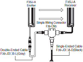
Cable for simple wiring * (2 cables per set, one double-ended cable and one single-ended cable)
| Appearance | Contents | Cable length | Model | |
|---|---|---|---|---|
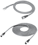 | Double-Ended Cable | F39-JD3B-L | 3 m | F39-JD0303BA |
| Single-Ended Cable | F39-JD3A-D | 3 m | ||
| Double-Ended Cable | F39-JD3B-L | 3 m | F39-JD0307BA | |
| Single-Ended Cable | F39-JD7A-D | 7 m | ||
| Double-Ended Cable | F39-JD3B-L | 3 m | F39-JD0310BA | |
| Single-Ended Cable | F39-JD10A-D | 10 m | ||
| Double-Ended Cable | F39-JD5B-L | 5 m | F39-JD0503BA | |
| Single-Ended Cable | F39-JD3A-D | 3 m | ||
| Double-Ended Cable | F39-JD5B-L | 5 m | F39-JD0507BA | |
| Single-Ended Cable | F39-JD7A-D | 7 m | ||
| Double-Ended Cable | F39-JD5B-L | 5 m | F39-JD0510BA | |
| Single-Ended Cable | F39-JD10A-D | 10 m | ||
| Double-Ended Cable | F39-JD10B-L | 10 m | F39-JD1003BA | |
| Single-Ended Cable | F39-JD3A-D | 3 m | ||
| Double-Ended Cable | F39-JD10B-L | 10 m | F39-JD1007BA | |
| Single-Ended Cable | F39-JD7A-D | 7 m | ||
| Double-Ended Cable | F39-JD10B-L | 10 m | F39-JD1010BA | |
| Single-Ended Cable | F39-JD10A-D | 10 m | ||
Note: A double-ended cable and single-ended cable with other cable lengths than those listed above can also be used in
combination.
Please contact your OMRON sales representative for details.
* Although the double-ended cable for the emitter is used for the emitter in the above figure, it can also be used for the
receiver.
Relays with Forcibly Guided Contacts
| Type | Appearance | Specifications | Model | Remarks |
|---|---|---|---|---|
| G7SA Relays with Forcibly Guided Contacts |  | Nodes: 4 Contact type: 2NO+2NC Rated switch load: 250 VAC 6A, 30 VDC 6A | G7SA-2A2B | For details on other models or socket models, refer to the OMRON's website. |
| Nodes: 4 Contact type: 3NO+1NC Rated switch load: 250 VAC 6A, 30 VDC 6A | G7SA-3A1B | |||
| G7S-[]-E Relays with Forcibly Guided Contacts |  | Nodes: 6 Contact type: 4NO+2NC Rated switch load: 250 VAC 10 A, 30 VDC 10 A | G7S-4A2B-E | For details on other models or socket models, refer to the OMRON's website. |
| Nodes: 6 Contact type: 3NO+3NC Rated switch load: 250 VAC 10 A, 30 VDC 10 A | G7S-3A3B-E |
Test rod (Sold separately)
| Diameter | Model |
|---|---|
| 14mm dia. | F39-TRD14 |
| 20mm dia. | F39-TRD20 |
| 25mm dia. | F39-TRD25 |
| 30mm dia. | F39-TRD30 |
Control Unit (Can not be used as a muting system)
(Dedicated PNP output type)
| Appearance | Output | Model | Remarks |
|---|---|---|---|
 | Relay, 3NO+1NC | F3SP-B1P * | For connection with F3SJ-B, use a double-ended cable F39-JD[]B. |
* F3SJ for NPN output type cannot be connected.
Wire-saving Devices
| Type | Appearance | Specifications | Model | Remarks |
|---|---|---|---|---|
| Connector Terminal Box/ Muting Terminals *2 |  | Model with PNP Muting Sensor Output | F39-TC5P01 | Significantly reduces amount of wiring between Safety Light Curtains and Muting Sensors. IP67 model for mounting at Sensor installation site. For details, refer to the OMRON's website. |
| Model with PNP Override Input | F39-TC5P02 | |||
| Model with NPN Muting Sensor Output | F39-TC5N01 | |||
| Model with NPN Override Input | F39-TC5N02 | |||
| Safety Terminal Relays *2 |  | PNP output relay, SPDT-NO | F3SP-T01 *1 | Significantly reduces amount of wiring between Safety Light Curtains and Muting Sensors. For details, refer to the OMRON's website. |
*1. F3SJ for NPN output type cannot be connected.
*2. The models with the suffix "-01TS" cannot be connected.
Laser Pointer
| Appearance | Output | Model |
|---|---|---|
 | Laser Pointer for F3SJ | F39-PTJ * |
* It cannot be mounted to the models with the suffix "-02TS".
Spatter Protection Cover (2 covers per set, one for emitter and one for receiver) (10% Operating Range Attenuation)
| Appearance | Model |
|---|---|
 | F39-HB[][][][] *1 *2 |
*1. The same 4-digit numbers as the protective heights ([][][][] in the light curtain model names) are substituted by in
the model names.
*2. It cannot be mounted to the models with the suffix "-02TS".
Protective Bar
| Appearance | Model | Remarks |
|---|---|---|
 | F39-PB[][][][] *1 | 2 Light Curtain brackets 4 mounting brackets 0 to 4 intermediate brackets for backside mounting (quantity required for the sensing width) 0 to 4 intermediate brackets for mounting to the sides (quantity required for the sensing width) |
| F39-PB[][][][]-S *1 *2 | 1 Light Curtain bracket 2 mounting brackets 0 to 2 intermediate brackets for backside mounting (quantity required for the sensing width) 0 to 2 intermediate brackets for mounting to the sides (quantity required for the sensing width) |
Note: The following are not provided with the Protective Bars.
•Safety Light Curtain
•Safety Light Curtain Top/Bottom Brackets
•Wall Mounting Screw Unit
*1. The same four digits indicating protective height that are used in the Sensor model number ([][][][]) are used in the
part of the Protector model number.
*2. Purchase the F39-PB[][][][] (which contains two sets of brackets) to use Protective Bars for both the Emitter and
Receiver.
Mirrors (12% Operating Range Attenuation)
| Appearance | Mirror material | Width (mm) | Thickness (mm) | Length L (mm) | Model | Remarks |
|---|---|---|---|---|---|---|
 | Glass mirror | 145 | 32 | 445 | F39-MLG0406 | 2 sets of cylinder mounting brackets and 4 screws are included. |
| 648 | F39-MLG0610 | |||||
| 749 | F39-MLG0711 | |||||
| 953 | F39-MLG0914 | |||||
| 1,105 | F39-MLG1067 | |||||
| 1,257 | F39-MLG1219 | |||||
| 1,499 | F39-MLG1422 | |||||
| 1,702 | F39-MLG1626 | |||||
| 1,905 | F39-MLG1830 | |||||
| 2,210 | F39-MLG2134 |
Sensor mounting bracket (Sold separately)
| Appearance | Specifications | Model | Application | Remarks |
|---|---|---|---|---|
 | Top/bottom bracket | F39-LJB1 | Top/bottom bracket for F3SJ-E/B | 2 for an emitter, 2 for a receiver, total of 4 per set |
 | Intermediate bracket | F39-LJB2 *1 *2 | In combination use with top/bottom bracket for F3SJ-E/B Can be used as free-location bracket. | 1 set with 2 pieces |
 | One-touch bracket | F39-LJB3-M6 *1 | One-touch bracket for F3SJ-E/B Supports M6 slide nut for aluminum frame. | 1 set with 2 pieces |
| F39-LJB3-M8 *2 | One-touch bracket for F3SJ-E/B Supports M8 slide nut for aluminum frame. | |||
 | One-touch M6 bracket One-touch M8 bracket | F39-LJB3-M6K *1 | Bracket to mount an intermediate bracket to the aluminum frame with a single touch. | Hexagon socket head cap screws (M6 x 10) are included. |
| F39-LJB3-M8K *2 | Hexagon socket head cap screws (M8 x 14) are included. | |||
 | Compatible mounting bracket | F39-LJB4 | Mounting bracket used when replacing existing area sensors (F3SJ-A or F3SN) with the F3SJ-E/B. | 2 for an emitter, 2 for a receiver, total of 4 per set |
 | Contact mount bracket | F39-LJB5 | Bracket to closely contact the back side of the Sensor. | 2 for an emitter, 2 for a receiver, total of 4 per set |
*1. Combining F39-LJB2 and F39-LJB3-M6K makes F39-LJB3-M6.
*2. Combining F39-LJB2 and F39-LJB3-M8K makes F39-LJB3-M8.
End Cap
| Appearance | Model | Remarks |
|---|---|---|
 | F39-CN11 * | For both emitter and receiver. The End Cap can be purchased if lost. (Case: Black) |
* This product is for F3SJ-B only.
Key Cap for Muting
| Appearance | Model | Remarks |
|---|---|---|
 | F39-CN10 *1 *2 | A cap to be attached to the main unit to enable muting function. Attach it to either an emitter or a receiver. (Case: orange) |
*1. This product is for F3SJ-B only.
*2. The models with the suffix "-01TS" cannot be connected.
F3SJ-A
Main Units
Safety Light Curtain
| Application | Detection capability | Beam gap | Operating range | Protective height (mm) | Model | |
|---|---|---|---|---|---|---|
| PNP Output | NPN Output | |||||
| Finger protection | Dia. 14 mm | 9 mm | 0.2 to 9 m | 245 to 1,271 | F3SJ-A[][][][]P14 *2 | F3SJ-A[][][][]N14 |
| Hand protection | Dia. 20 mm | 15 mm | 0.2 to 9 m | 245 to 1,505 | F3SJ-A[][][][]P20 *2 | F3SJ-A[][][][]N20 |
| Hand/arm protection | Dia. 30 mm | 25 mm | 0.2 to 9 m | 245 to 1,620 | F3SJ-A[][][][]P30 *1 | F3SJ-A[][][][]N30 |
| 0.2 to 7 m | 1,745 to 2,495 | |||||
| Leg/body protection, presence detection | Dia. 55 mm | 50 mm | 0.2 to 9 m | 270 to 1,570 | F3SJ-A[][][][]P55 *1 | F3SJ-A[][][][]N55 |
| 0.2 to 7 m | 1,670 to 2,470 | |||||
Note: Connection cables are not included in the products. You must purchase optional connector cable.
*1. Models with S-mark certification have an "-S" at the end of the model number.
Example: F3SJ-A0245P30-S
*2. The F3SJ-A-[][][][]-TS series with the suffix "-TS" are auto reset fixed models. Function settings using the setting
console F39-MC21 or PC tool F39-GWUM for F3SJ cannot be performed.
(Models with ditection capability 25 mm dia. are also available.)
Safety Light Curtain Model List
F3SJ-A14 Series (9 mm gap)
| Model | Number of Beams | Protective Height (mm) * | |
|---|---|---|---|
| PNP Output | NPN Output | ||
| F3SJ-A0245P14 | F3SJ-A0245N14 | 26 | 245 |
| F3SJ-A0263P14 | F3SJ-A0263N14 | 28 | 263 |
| F3SJ-A0299P14 | F3SJ-A0299N14 | 32 | 299 |
| F3SJ-A0317P14 | F3SJ-A0317N14 | 34 | 317 |
| F3SJ-A0389P14 | F3SJ-A0389N14 | 42 | 389 |
| F3SJ-A0461P14 | F3SJ-A0461N14 | 50 | 461 |
| F3SJ-A0551P14 | F3SJ-A0551N14 | 60 | 551 |
| F3SJ-A0623P14 | F3SJ-A0623N14 | 68 | 623 |
| F3SJ-A0695P14 | F3SJ-A0695N14 | 76 | 695 |
| F3SJ-A0731P14 | F3SJ-A0731N14 | 80 | 731 |
| F3SJ-A0803P14 | F3SJ-A0803N14 | 88 | 803 |
| F3SJ-A0875P14 | F3SJ-A0875N14 | 96 | 875 |
| F3SJ-A0983P14 | F3SJ-A0983N14 | 108 | 983 |
| F3SJ-A1055P14 | F3SJ-A1055N14 | 116 | 1,055 |
| F3SJ-A1127P14 | F3SJ-A1127N14 | 124 | 1,127 |
| F3SJ-A1199P14 | F3SJ-A1199N14 | 132 | 1,199 |
| F3SJ-A1271P14 | F3SJ-A1271N14 | 140 | 1,271 |
* Protective Height (mm) = Total sensor length
F3SJ-A20 Series (15 mm gap)
| Model | Number of Beams | Protective Height (mm) * | |
|---|---|---|---|
| PNP Output | NPN Output | ||
| F3SJ-A0245P20 | F3SJ-A0245N20 | 16 | 245 |
| F3SJ-A0275P20 | F3SJ-A0275N20 | 18 | 275 |
| F3SJ-A0305P20 | F3SJ-A0305N20 | 20 | 305 |
| F3SJ-A0395P20 | F3SJ-A0395N20 | 26 | 395 |
| F3SJ-A0455P20 | F3SJ-A0455N20 | 30 | 455 |
| F3SJ-A0545P20 | F3SJ-A0545N20 | 36 | 545 |
| F3SJ-A0605P20 | F3SJ-A0605N20 | 40 | 605 |
| F3SJ-A0635P20 | F3SJ-A0635N20 | 42 | 635 |
| F3SJ-A0695P20 | F3SJ-A0695N20 | 46 | 695 |
| F3SJ-A0785P20 | F3SJ-A0785N20 | 52 | 785 |
| F3SJ-A0815P20 | F3SJ-A0815N20 | 54 | 815 |
| F3SJ-A0875P20 | F3SJ-A0875N20 | 58 | 875 |
| F3SJ-A0935P20 | F3SJ-A0935N20 | 62 | 935 |
| F3SJ-A1025P20 | F3SJ-A1025N20 | 68 | 1,025 |
| F3SJ-A1115P20 | F3SJ-A1115N20 | 74 | 1,115 |
| F3SJ-A1205P20 | F3SJ-A1205N20 | 80 | 1,205 |
| F3SJ-A1265P20 | F3SJ-A1265N20 | 84 | 1,265 |
| F3SJ-A1445P20 | F3SJ-A1445N20 | 96 | 1,445 |
| F3SJ-A1505P20 | F3SJ-A1505N20 | 100 | 1,505 |
* Protective Height (mm) = Total sensor length
F3SJ-A30 Series (25 mm gap)
| Model | Number of Beams | Protective Height (mm) * | |
|---|---|---|---|
| PNP Output | NPN Output | ||
| F3SJ-A0245P30 | F3SJ-A0245N30 | 10 | 245 |
| F3SJ-A0295P30 | F3SJ-A0295N30 | 12 | 295 |
| F3SJ-A0395P30 | F3SJ-A0395N30 | 16 | 395 |
| F3SJ-A0470P30 | F3SJ-A0470N30 | 19 | 470 |
| F3SJ-A0520P30 | F3SJ-A0520N30 | 21 | 520 |
| F3SJ-A0545P30 | F3SJ-A0545N30 | 22 | 545 |
| F3SJ-A0570P30 | F3SJ-A0570N30 | 23 | 570 |
| F3SJ-A0620P30 | F3SJ-A0620N30 | 25 | 620 |
| F3SJ-A0720P30 | F3SJ-A0720N30 | 29 | 720 |
| F3SJ-A0795P30 | F3SJ-A0795N30 | 32 | 795 |
| F3SJ-A0870P30 | F3SJ-A0870N30 | 35 | 870 |
| F3SJ-A0920P30 | F3SJ-A0920N30 | 37 | 920 |
| F3SJ-A0945P30 | F3SJ-A0945N30 | 38 | 945 |
| F3SJ-A0995P30 | F3SJ-A0995N30 | 40 | 995 |
| F3SJ-A1020P30 | F3SJ-A1020N30 | 41 | 1,020 |
| F3SJ-A1095P30 | F3SJ-A1095N30 | 44 | 1,095 |
| F3SJ-A1120P30 | F3SJ-A1120N30 | 45 | 1,120 |
| F3SJ-A1195P30 | F3SJ-A1195N30 | 48 | 1,195 |
| F3SJ-A1270P30 | F3SJ-A1270N30 | 51 | 1,270 |
| F3SJ-A1395P30 | F3SJ-A1395N30 | 56 | 1,395 |
| F3SJ-A1620P30 | F3SJ-A1620N30 | 65 | 1,620 |
| F3SJ-A1745P30 | F3SJ-A1745N30 | 70 | 1,745 |
| F3SJ-A1870P30 | F3SJ-A1870N30 | 75 | 1,870 |
| F3SJ-A1995P30 | F3SJ-A1995N30 | 80 | 1,995 |
| F3SJ-A2245P30 | F3SJ-A2245N30 | 90 | 2,245 |
| F3SJ-A2370P30 | F3SJ-A2370N30 | 95 | 2,370 |
| F3SJ-A2495P30 | F3SJ-A2495N30 | 100 | 2,495 |
* Protective Height (mm) = Total sensor length
F3SJ-A55 Series (50 mm gap)
| Model | Number of Beams | Protective Height (mm) * | |
|---|---|---|---|
| PNP Output | NPN Output | ||
| F3SJ-A0270P55 | F3SJ-A0270N55 | 6 | 270 |
| F3SJ-A0320P55 | F3SJ-A0320N55 | 7 | 320 |
| F3SJ-A0370P55 | F3SJ-A0370N55 | 8 | 370 |
| F3SJ-A0470P55 | F3SJ-A0470N55 | 10 | 470 |
| F3SJ-A0570P55 | F3SJ-A0570N55 | 12 | 570 |
| F3SJ-A0620P55 | F3SJ-A0620N55 | 13 | 620 |
| F3SJ-A0720P55 | F3SJ-A0720N55 | 15 | 720 |
| F3SJ-A0770P55 | F3SJ-A0770N55 | 16 | 770 |
| F3SJ-A0870P55 | F3SJ-A0870N55 | 18 | 870 |
| F3SJ-A0920P55 | F3SJ-A0920N55 | 19 | 920 |
| F3SJ-A0970P55 | F3SJ-A0970N55 | 20 | 970 |
| F3SJ-A1020P55 | F3SJ-A1020N55 | 21 | 1,020 |
| F3SJ-A1120P55 | F3SJ-A1120N55 | 23 | 1,120 |
| F3SJ-A1170P55 | F3SJ-A1170N55 | 24 | 1,170 |
| F3SJ-A1270P55 | F3SJ-A1270N55 | 26 | 1,270 |
| F3SJ-A1320P55 | F3SJ-A1320N55 | 27 | 1,320 |
| F3SJ-A1420P55 | F3SJ-A1420N55 | 29 | 1,420 |
| F3SJ-A1570P55 | F3SJ-A1570N55 | 32 | 1,570 |
| F3SJ-A1770P55 | F3SJ-A1770N55 | 36 | 1,770 |
| F3SJ-A1920P55 | F3SJ-A1920N55 | 39 | 1,920 |
| F3SJ-A2070P55 | F3SJ-A2070N55 | 42 | 2,070 |
| F3SJ-A2220P55 | F3SJ-A2220N55 | 45 | 2,220 |
| F3SJ-A2370P55 | F3SJ-A2370N55 | 48 | 2,370 |
| F3SJ-A2470P55 | F3SJ-A2470N55 | 50 | 2,470 |
* Protective Height (mm) = Total sensor length
Accessories (Sold separately)
Single-Ended Cable (2 cables per set, one for emitter and one for receiver) *
For wiring with safety circuit such as single safety relay, safety relay unit, and safety controller
| Appearance | Cable length | Specifications | Model |
|---|---|---|---|
 | 3 m | M12 connector (8-pin) | F39-JD3A |
| 7 m | F39-JD7A | ||
| 10 m | F39-JD10A | ||
| 15 m | F39-JD15A | ||
| 20 m | F39-JD20A |
* The cable for emitter and the cable for receiver are available separately. Add '-L' for emitter or '-D' for receiver to the end
of the model number when you order.
Single-Ended Cable for Emitter: F39-JD[]A-L, Single-Ended Cable for Receiver: F39-JD[]A-D
Note: To extend the cable length to 20 m or more, add the F39-JD[]B Double-Ended Cable.
Example: When using a cable of 30 m, connect the F39-JD10A Single-Ended Cable with the F39-JD20B Double-Ended
Cable.
Double-Ended Cable (2 cables per set, one for emitter and one for receiver) *
Control unit for connection with F3SP-B1P, to extend the length under series connection (*)
| Appearance | Cable length | Specifications | Model |
|---|---|---|---|
 | 0.5 m | M12 connector (8-pin) | F39-JDR5B |
| 1 m | F39-JD1B | ||
| 3 m | F39-JD3B | ||
| 5 m | F39-JD5B | ||
| 7 m | F39-JD7B | ||
| 10 m | F39-JD10B | ||
| 15 m | F39-JD15B | ||
| 20 m | F39-JD20B |
* The cable for emitter and the cable for receiver are available separately. Add '-L' for emitter or '-D' for receiver to the end
of the model number when you order.
Double-Ended Cable for Emitter: F39-JD[]B-L, Double-Ended Cable for Receiver: F39-JD[]B-D
Note: To extend the cable length to 20 m or more, use the Double-Ended Cables in combination.
Example: When using a cable of 30 m, connect the F39-JD10B Double-Ended Cable with the F39-JD20B Double-
Ended Cable.

Power cable (included in the main unit. 2 cables per set, one for emitter and one for receiver)
| Appearance | Cable Length | Model |
|---|---|---|
 | 0.3 m | F39-JJR3K |
Note: This product is for F3SJ-A only.
Series-connection Cable (2 cables per set, for emitter and receiver)
| Type | Appearance | Cable Length | Model | Application |
|---|---|---|---|---|
| Series connection cable |  | 0.3 m | F39-JJR3W *1 | For series connection *2 When using the Water-resistant Case. *3 |
| Side-by-side Series connection cable |  | 0.06 m | F39-JJR06L *1 | Dedicated cable to materialize series connection with minimum length without connector cable of the main sensor unit |
| 0.15 m | F39-JJR15L *1 |
*1. This product is for F3SJ-A only.
*2. For series connection with minimum length, use F39-JJR06L or F39-JJR15L.
*3. When using the F39-EJ[][][][]-L/D Water-resistant Case in series connection configurations, use the special series
connection cables for the Water-resistant Case.
Refer to Catalog for details.
Note: The Double-Ended Cable (up to 15 m: F39-JD15B) can be added to extend the cable length between the series-
connected sensors.
Cable length between sensors: 15 m max. (not including series connection cable (F39-JJR3W or F39-JJR[]L) and
power cable)

Simple wiring connector system (Order the F39-CN5 and Cables for Simple Wiring.)
Simple wiring connector
| Appearance | Model | Application |
|---|---|---|
 | F39-CN5 | To reduce wiring |

Cable for simple wiring * (2 cables per set, one double-ended cable and one single-ended cable)
| Appearance | Contents | Cable length | Model | |
|---|---|---|---|---|
 | Double-Ended Cable | F39-JD3B-L | 3 m | F39-JD0303BA |
| Single-Ended Cable | F39-JD3A-D | 3 m | ||
| Double-Ended Cable | F39-JD3B-L | 3 m | F39-JD0307BA | |
| Single-Ended Cable | F39-JD7A-D | 7 m | ||
| Double-Ended Cable | F39-JD3B-L | 3 m | F39-JD0310BA | |
| Single-Ended Cable | F39-JD10A-D | 10 m | ||
| Double-Ended Cable | F39-JD5B-L | 5 m | F39-JD0503BA | |
| Single-Ended Cable | F39-JD3A-D | 3 m | ||
| Double-Ended Cable | F39-JD5B-L | 5 m | F39-JD0507BA | |
| Single-Ended Cable | F39-JD7A-D | 7 m | ||
| Double-Ended Cable | F39-JD5B-L | 5 m | F39-JD0510BA | |
| Single-Ended Cable | F39-JD10A-D | 10 m | ||
| Double-Ended Cable | F39-JD10B-L | 10 m | F39-JD1003BA | |
| Single-Ended Cable | F39-JD3A-D | 3 m | ||
| Double-Ended Cable | F39-JD10B-L | 10 m | F39-JD1007BA | |
| Single-Ended Cable | F39-JD7A-D | 7 m | ||
| Double-Ended Cable | F39-JD10B-L | 10 m | F39-JD1010BA | |
| Single-Ended Cable | F39-JD10A-D | 10 m | ||
Note: A double-ended cable and single-ended cable with other cable lengths than those listed above can also be used in
combination.
Please contact your OMRON sales representative for details.
* Although the double-ended cable for the emitter is used for the emitter in the above figure, it can also be used for the
receiver.
Relays with Forcibly Guided Contacts
| Type | Appearance | Specifications | Model | Remarks |
|---|---|---|---|---|
| G7SA Relays with Forcibly Guided Contacts |  | Nodes: 4 Contact type: 2A2B Rated switch load: 250 VAC 6 A, 30 VDC 6 A | G7SA-2A2B | For details on other models or socket models, refer to the OMRON's website. |
| Nodes: 4 Contact type: 3NO+1NC Rated switch load: 250 VAC 6 A, 30 VDC 6 A | G7SA-3A1B | |||
| G7S-[]-E Relays with Forcibly Guided Contacts |  | Nodes: 6 Contact type: 4NO+2NC Rated switch load: 250 VAC 10 A, 30 VDC 10 A | G7S-4A2B-E | For details on other models or socket models, refer to the OMRON's website. |
| Nodes: 6 Contact type: 3NO+3NC Rated switch load: 250 VAC 10 A, 30 VDC 10 A | G7S-3A3B-E |
Control Unit (Can not be used as a muting system)
(Dedicated PNP output type) *
| Appearance | Output | Model | Remarks |
|---|---|---|---|
 | Relay, 3NO+1NC | F3SP-B1P * | For connection with F3SJ-A, use a double-ended cable F39-JD[]B. |
* F3SJ for NPN output type cannot be connected.
Wire-saving Devices
| Type | Appearance | Specifications | Model | Remarks |
|---|---|---|---|---|
| Connector Terminal Box/Muting Terminals |  | Model with PNP Muting Sensor Output | F39-TC5P01 | Significantly reduces amount of wiring between Safety Light Curtains and Muting Sensors. IP67 model for mounting at Sensor installation site. For details, refer to the OMRON's website. |
| Model with PNP Override Input | F39-TC5P02 | |||
| Model with NPN Muting Sensor Output | F39-TC5N01 | |||
| Model with NPN Override Input | F39-TC5N02 | |||
| Safety Terminal Relays |  | PNP output relay, SPDT-NO | F3SP-T01 * | Significantly reduces amount of wiring between Safety Light Curtains and Muting Sensors. For details, refer to the OMRON's website. |
* F3SJ for NPN output type cannot be connected.
Laser Pointer
| Appearance | Output | Model |
|---|---|---|
 | Laser Pointer for F3SJ | F39-PTJ |
Dedicated External Indicator Set (can be connected to either an emitter or a receiver)
| Appearance | Color | Model | Remarks |
|---|---|---|---|
 | Red | F39-A01PR-PAC | Indicator (red), mounting bracket 1 set, and dedicated connection cable (0.1 m) |
| Green | F39-A01PG-PAC | Indicator (green), mounting bracket 1 set, and dedicated connection cable (0.1 m) | |
| Yellow | F39-A01PY-PAC | Indicator (yellow), mounting bracket 1 set, and dedicated connection cable (0.1 m) |
Note: 1. For indication timing (operation mode), see "Specifications" on Catalog.
2. This product is for F3SJ-A only.
General External Indicator Cable
| Appearance | Cable Length | Specifications | Model |
|---|---|---|---|
 | 3 m | Cable to connect top of the main unit and an off-the-shelf external indicator (2-wire) | F39-JJ3N * |
* This product is for F3SJ-A only.
Spatter Protection Cover (2 cables per set, one for emitter and one for receiver) (10% Operating Range Attenuation)
| Appearance | Model |
|---|---|
 | F39-HJ[][][][] *1 *2 |
*1. This product is for F3SJ-A only.
*2. The same 4-digit numbers as the protective heights ([][][][] in the light curtain model names) are substituted by in
the model names.
Mirrors (12% Operating Range Attenuation)
| Appearance | Mirror material | Width (mm) | Thickness (mm) | Length L (mm) | Model | Remarks |
|---|---|---|---|---|---|---|
 | Glass mirror | 145 | 32 | 445 | F39-MLG0406 | 2 sets of cylinder mounting brackets and 4 screws are included. |
| 648 | F39-MLG0610 | |||||
| 749 | F39-MLG0711 | |||||
| 953 | F39-MLG0914 | |||||
| 1,105 | F39-MLG1067 | |||||
| 1,257 | F39-MLG1219 | |||||
| 1,499 | F39-MLG1422 | |||||
| 1,702 | F39-MLG1626 | |||||
| 1,905 | F39-MLG1830 | |||||
| 2,210 | F39-MLG2134 |
Test rod (Sold separately)
| Diameter | Model |
|---|---|
| 14mm dia. | F39-TRD14 |
| 20mm dia. | F39-TRD20 |
| 25mm dia. | F39-TRD25 |
| 30mm dia. | F39-TRD30 |
Sensor Mounting Brackets (Sold separately)
| Appearance | Specifications | Model | Application | Remarks |
|---|---|---|---|---|
 | Standard mounting bracket (for top/bottom) | F39-LJ1 | (provided with the F3SJ) | 2 for an emitter, 2 for a receiver, total of 4 per set |
 | Flat side mounting bracket | F39-LJ2 | Use these small-sized brackets when performing side mounting with standard mounting brackets, so that they do not protrude from the detection surface. | 2 for an emitter, 2 for a receiver, total of 4 per set |
 | Free-location mounting bracket (also used as standard intermediate bracket) | F39-LJ3 | Use these brackets for mounting on any place without using standard bracket. | Two brackets per set (For details about the number of required brackets, refer to Data Sheet.) |
 | F3SN Intermediate Bracket Replacement Spacers | F39-LJ3-SN | When replacing the F3SN with the F3SJ, the mounting hole pitches in the Intermediate Brackets are not the same. This Spacer is placed between the mounting holes to mount the F3SJ. | 1 set with 2 pieces |
 | Top/bottom bracket B (Mounting hole pitch 19 mm) | F39-LJ4 | Mounting bracket used when replacing existing area sensors (other than F3SN or F3WN) with the F3SJ. For front mounting. Suitable for mounting hole pitch of 18 to 20 mm. | 2 for an emitter, 2 for a receiver, total of 4 per set |
 | Bracket for replacing short-length F3SN | F39-LJ5 | Mounting bracket used when an F3SN with protective height of 300 mm or less is replaced by an F3SJ. | 2 for an emitter, 2 for a receiver, total of 4 per set |
 | Space-saving mounting bracket | F39-LJ8 | Use these brackets to mount facing inward. Length is 12 mm shorter than the standard F39-LJ1 bracket. | 2 for an emitter, 2 for a receiver, total of 4 per set |
 | Mounting bracket used when replacing an F3W-C. | F39-LJ9 | Mounting bracket used when replacing existing F3W-C series area sensors with the F3SJ. For front mounting or side mounting. Mounting hole pitch 16 mm. | 2 for an emitter, 2 for a receiver, total of 4 per set |
 | Top/bottom bracket C (mounting hole pitch 13 mm) | F39-LJ11 | Mounting bracket used when replacing existing area sensors having a mounting pitch of 13 mm with the F3SJ. | 2 for an emitter, 2 for a receiver, total of 4 per set |
End Cap
| Appearance | Model | Remarks |
|---|---|---|
 | F39-CN9 * | For both emitter and receiver. The End Cap can be purchased if lost. (Case: Black) |
* This product is for F3SJ-A only.
Key Cap for Muting
| Appearance | Model | Remarks |
|---|---|---|
 | F39-CN6 * | A cap to be attached to the main unit to enable muting function. Attach it to either an emitter or a receiver. (Case: orange) |
* This product is for F3SJ-A only.
Setting Tools *1
| Type | Appearance | Model | Remarks |
|---|---|---|---|
| "SD Manager" Setting Support Software for the F3SJ |  | F39-GWUM *2 | Accessories: SD Manager CD-ROM (1), F39-CN1 Branch Connector (1), Connector Cap (1), 2-m Dedicated Cable (1), 0.3-m Dedicated Cable with Plug (1), Instruction Manual |
| Setting Console |  | F39-MC21 *3 | Accessories: F39-CN1 Branch Connector (1), Connector Cap (1), 2-m Dedicated Cable (1), 0.3-m Dedicated Cable with Plug (1), Instruction Manual |
*1. The setting tools described above can be connected only to F3SJ-A models with built-in software of Ver. 2 or later.
Note that the setting tools cannot be used with products shipped prior to December 2005.
The setting tools cannot be used for setting parameters on the F3SJ-A[]-TS series, but the monitoring function can
be used.
*2. The PC tool supports Windows XP/7.
*3. This product is for use only with the F3SJ-A.It cannot be connected to conventional models of the F3SJ-E/B or F3SN-A
series.
Similarly, the F39-MC11 and F39-MT11 Dedicated Consoles for the F3SN-A cannot be connected to the F3SJ-A series.
Protective Bar *1 *2
| Type | Appearance | Model | Remarks |
|---|---|---|---|
| Protective Bar |  | F39-PJ[][][][]-S *3 | Main unit bracket (1), rear mounting brackets (2), including intermediate brackets to match protective height (0 to 2). |
| Intermediate brackets for side mounting |  | F39-PJ-MS | For side mounting, order to suit the desired protective height. Protective height of up to 1,000 mm: 0 intermediate brackets Protective height of 1,001 to 2,000 mm: 1 intermediate bracket Protective height of 2,001 mm or more: 2 intermediate brackets |
*1. This product is for F3SJ-A only.
*2. When using for both emitter and receiver, order two sets.
*3. The same four digits indicating protective height that are used in the Sensor model number ([][][][]) are used in
the part of the Protector model number.
Water-resistant Case (Set of 1 tube, packing, and dedicated connector cable) *1 *2 *3
| Appearance | Specifications | Model | Remarks |
|---|---|---|---|
 | For emitter | F39-EJ[][][][]-L *4 | Includes gray cable for emitter. |
| For receiver | F39-EJ[][][][]-D *4 | Includes black cable for receiver. | |
 | Rear Mounting Brackets | F39-EJ-R *5 | Top/bottom 1 each, total of 2 |
 | Side Mounting Brackets | F39-EJ-S *5 | Top/bottom 1 each, total of 2 |
| --- | Series connection cable (for emitter) | F39-JJR3WE-L | Purchase additionally for series connection when using the Water-resistant Case. |
| Series connection cable (for receiver) | F39-JJR3WE-D |
*1. This product is for F3SJ-A only.
*2. When using for both emitter and receiver, order two sets.
*3. There are restrictions to the application conditions depending on the protective height of the Curtain. Refer to the
Water-resistant Case on Catalog.
*4. The same four digits indicating protective height that are used in the Sensor model number ([][][][]) are used in
the part of the Protector model number.
*5. Be sure to purchase brackets with the Case to match the mounting direction (rear or side).
last update: June 11, 2018
OMRON F3SJ Series specification
F3SJ Series Safety Light Curtain/Specificationslast update: October 15, 2018
F3SJ-E
Main Units
F3SJ-E[][][][]P25/N25
| Model | PNP output | F3SJ-E[][][][]P25 |
|---|---|---|
| NPN output | F3SJ-E[][][][]N25 | |
| Sensor type | Type 4 safety light curtain | |
| Setting tool connection *1 | Parameter settings: Not available | |
| Safety category | Safety purpose of category 4, 3, 2, 1, or B | |
| Detection capability | Opaque objects 25 mm in diameter | |
| Beam gap (P) | 20 mm | |
| Number of beams (n) | 8 to 54 | |
| Protective height (PH) | 185 to 1,105 mm | |
| Lens diameter | Diameter 5 mm | |
| Operating range *2 | 0.2 to 7 m | |
| Response time (under stable light incident condition) | ON to OFF | 15 ms max. |
| OFF to ON | 70 ms max. | |
| Startup waiting time | 2 s max. | |
| Power supply voltage (Vs) | SELV/PELV 24 VDC±20% (ripple p-p 10% max.) | |
| Consumption current (no load) | PNP output | Emitter: Up to 22 beams: 41 mA max., 26 to 42 beams: 57 mA max., 46 to 54 beams: 63 mA max. Receiver: Up to 22 beams: 42 mA max., 26 to 42 beams: 47 mA max., 46 to 54 beams: 51 mA max. |
| NPN output | Emitter: Up to 22 beams: 41 mA max., 26 to 42 beams: 57 mA max., 46 to 54 beams: 63 mA max. Receiver: Up to 22 beams: 40 mA max., 26 to 42 beams: 45 mA max., 46 to 54 beams: 48 mA max. | |
| Light source (emitted wavelength) | Infrared LED (870 nm) | |
| Effective aperture angle (EAA) | Based on IEC 61496-2. Within ±2.5° for both emitter and receiver when the detection distance is 3 m or over | |
| Safety outputs (OSSD) | PNP output | Two PNP transistor outputs, load current 200 mA max., residual voltage 2 V max. (except for voltage drop due to cable extension), Leakage current 1 mA max., load inductance 2.2 H max. *3, Maximum capacity load 1 μF *4 |
| NPN output | Two NPN transistor outputs, load current 200 mA max., residual voltage 2 V max. (except for voltage drop due to cable extension), Leakage current 1 mA max., load inductance 2.2 H max. *3, Maximum capacity load 1 μF *4 | |
| Output operation mode | Safety output: On when receiving light | |
| Input voltage | PNP output | Test input: ON voltage: Vs-3 V to Vs (short circuit current: approx. 3.0 mA) *5 OFF voltage: 0 V to 1/2 Vs or open (short circuit current: approx. 4.0 mA) *5 |
| NPN output | Test input: ON voltage: 0 to 3 V (short circuit current: approx. 4.0 mA) OFF voltage: 1/2 Vs to Vs or open (short circuit current: approx. 3.0 mA) *5 | |
| Mutual interference prevention function | Mutual interference prevention algorithm prevents interference in up to 3 sets. | |
| Test function | Self test (at power-ON and at power distribution) External test (emission stop function by test input) | |
| Protection circuit | Output short-circuit protection, and power supply reverse polarity protection | |
| Ambient temperature | Operating: -10 to 55°C (non-freezing), Storage: -25 to 70°C | |
| Ambient humidity | Operating: 35% to 85% (no condensation), Storage: 35% to 95% RH | |
| Operating ambient light intensity | Incandescent lamp: 3,000 lx max., Sunlight: 10,000 lx max. | |
| Insulation resistance | 20 MΩ min. (at 500 VDC) | |
| Dielectric strength | 1,000 VAC 50/60 Hz, 1 min | |
| Degree of protection | IP65 (IEC 60529) | |
| Vibration resistance | Malfunction: 10 to 55 Hz, Multiple amplitude of 0.7 mm, 20 sweeps in X, Y, and Z directions | |
| Shock resistance | Malfunction: 100 m/s2, 1,000 times each in X, Y, and Z directions | |
| Pollution degree | Pollution degree 3 (IEC 60664-1) | |
| Power cable | Connection method: Pull-out type, cable length 3 m Number of wires: Emitter: 5 wires, receiver: 6 wires Cable diameter: Dia. 6 mm Allowable bending radius: R5 mm | |
| Extension cable | 30 m max. *6 | |
| Material | Case: Aluminum Cap: ABS resin, PBT Optical cover: PMMA resin (acrylic) Cable: Oil resistant PVC | |
| Net Weight *7 | Weight (g) = (protective height) x 1.59 + 330 | |
| Gross Weight *8 | Weight (g) = (protective height) x 2.6 + 800 | |
| Accessories | Instruction Manual, Quick Installation Manual (QIM) *9 | |
| Applicable standards | IEC 61496-1, EN 61496-1, UL 61496-1, Type 4 ESPE (Electro-Sensitive Protective Equipment) IEC 61496-2, EN 61496-2, UL 61496-2, Type 4 AOPD (Active Opto-electronic Protective Devices) IEC 61508-1 to -3, EN 61508-1 to -3 SIL3 ISO 13849-1: 2006, EN ISO 13849-1: 2008 (PLe/Safety Category 4) UL 508, UL 1998, CAN/CSA C22.2 No.14, CAN/CSA C22.2 No.0.8 | |
*1. Do not use the Support Software and Setting Console for F3SJ-A. Operation cannot be guaranteed.
*2. Use of the Spatter Protection Cover causes a 10% maximum sensing distance attenuation.
*3. The load inductance is the maximum value when the safety output frequently repeats ON and OFF. When you use the
safety output at 4 Hz or less, the usable load inductance becomes larger.
*4. These values must be taken into consideration when connecting elements including a capacitive load such as capacitor.
*5. The Vs indicates a voltage value in your environment.
*6. To extend a cable of the F3SJ-E, refer to the User's Manual (SCHG-733/732).
*7. The net weight is the weight of an emitter and a receiver.
*8. The gross weight is the weight of an emitter, a receiver, included accessories and a package.
*9. Mounting brackets and test rod are sold separately.
Indicator
Emitter
| Nameofindicator | Label | ON | Blinking |
|---|---|---|---|
| Top-beam-state indicator | TOP | Turns ON when the top beam is receiving light. | --- |
| Stable-state indicator | STB | Turns ON when incidence level is more than 170% of the output ON threshold. | Blinks when the safety output is turned OFF due to disturbance light or vibration. |
| ON/OFF-state indicator | ON OFF | Green: Turns ON when safety output is ON. Red: Turns OFF when safety output is OFF. | Red: Blinks when the F3SJ-E enters a lockout due to a safety output error. |
| Lockout indicator | LOCKOUT | Turns ON when the F3SJ-E enters a lockout on the receiver. | Blinks when the F3SJ-E enters a lockout on the emitter. |
| Power indicator | POWER | Turns ON while the power of the emitter is ON. | Blinks when the F3SJ-E enters a lockout due to power voltage/noise. |
| Test indicator | TEST | --- | Blinks when external test is being performed. |
| Bottom-beam- state indicator | BTM | Turns ON when the bottom beam is receiving light. | --- |
Receiver
| Nameofindicator | Label | ON | Blinking |
|---|---|---|---|
| Top-beam-state indicator | TOP | Turns ON when the top beam is receiving light. | --- |
| Stable-state indicator | STB | Turns ON when incidence level is more than 170% of the output ON threshold. | Blinks when the safety output is turned OFF due to disturbance light or vibration. |
| ON/OFF-state indicator | ON OFF | Green: Turns ON when safety output is ON. Red: Turns OFF when safety output is OFF. | Red: Blinks when the F3SJ-E enters a lockout due to a safety output error. |
| Lockout indicator | LOCKOUT | Turns ON when the F3SJ-E enters a lockout on the emitter. | Blinks when the F3SJ-E enters a lockout on the receiver. |
| Communication indicator | COM | Turns ON when communication between emitter and receiver is established. | Blinks when the F3SJ-E enters lockout due to a communication error between receiver and emitter. |
| Configuration indicator | CFG | --- | Blinks when the F3SJ-E enters lockout due to a model type error between receiver and emitter. |
| Internal error indicator | INTERNAL | --- | Blinks when the F3SJ-E enters a lockout due to an internal error. |
| Bottom-beam- state indicator | BTM | Turns ON when the bottom beam is receiving light. | --- |
Accessories
Laser Pointer
| Model | F39-PTJ |
|---|---|
| Applicable sensor | F3SJ Series |
| Power supply voltage | 4.65 or 4.5 VDC |
| Battery | Three button batteries (SR44 or LR44) |
| Battery life * | SR44: 10 hours of continuous operation, LR44: 6 hours of continuous operation |
| Light source | Red semiconductor laser (wavelength: 650 nm, 1 mW max. JIS class 2, EN/IEC class 2, FDA class II) |
| Spot diameter (typical value) | 6.5 mm at 10 m |
| Ambient temperature | Operating: 0 to 40°C, Storage: -15 to 60°C (with no icing or condensation) |
| Ambient humidity | Operating and storage: 35% to 85% (with no condensation) |
| Material | Laser module case: aluminum, Mounting bracket: aluminum and stainless |
| Weight | Approx. 220 g (packed) |
| Accessories | Laser safety standard labels (EN: 1, FDA: 3) Button batteries (SR44: 3), instruction manual |
* Battery life varies depending on a battery used.
F3SJ-B
Main Units
F3SJ-B[][][][]P25/N25
| Model | PNP output | F3SJ-B[][][][]P25 |
|---|---|---|
| NPN output | F3SJ-B[][][][]N25 | |
| Sensor type | Type 4 safety light curtain | |
| Setting tool connection *1 | Parameter settings: Not available | |
| Safety category | Safety purpose of category 4, 3, 2, 1, or B | |
| Detection capability | Opaque objects 25mm in diameter | |
| Beam gap (P) | 20 mm | |
| Number of beams (n) | 8 to 102 | |
| Protective height (PH) | 185 to 2,065 mm | |
| Lens diameter | Diameter 5 mm | |
| Operating range *2 | 0.2 to 7 m | |
| Response time (under stable light incident condition) | ON to OFF | 15 ms max. (response time at 1 set connection, series connection of 2 sets or 3 sets) |
| OFF to ON | 70 ms max. (response time at 1 set connection, series connection of 2 sets or 3 sets) | |
| Startup waiting time | 2 s max. | |
| Power supply voltage (Vs) | SELV/PELV 24 VDC±20% (ripple p-p 10% max.) | |
| Consumption current (no load) | PNP output | Emitter: Up to 22 beams: 52 mA max., 26 to 42 beams: 68 mA max., 46 to 62 beams: 75 mA max., 66 to 82 beams: 88 mA max., 86 to 102 beams: 101 mA max. Receiver: Up to 22 beams: 45 mA max., 26 to 42 beams: 50 mA max., 46 to 62 beams: 56 mA max., 66 to 82 beams: 61 mA max., 86 to 102 beams: 67 mA max. |
| NPN output | Emitter: Up to 22 beams: 52 mA max., 26 to 42 beams: 68 mA max., 46 to 62 beams: 75 mA max., 66 to 82 beams: 88 mA max., 86 to 102 beams: 101 mA max. Receiver: Up to 22 beams: 47 mA max., 26 to 42 beams: 52 mA max., 46 to 62 beams: 58 mA max., 66 to 82 beams: 63 mA max., 86 to 102 beams: 69 mA max. | |
| Light source (emitted wavelength) | Infrared LED (870 nm) | |
| Effective aperture angle (EAA) | Based on IEC 61496-2.Within +/-2.5° for both emitter and receiver when the detection distance is 3 m or over | |
| Safety outputs (OSSD) | PNP output | Two PNP transistor outputs, load current 200 mA max., residual voltage 2 V max. (except for voltage drop due to cable extension), Leakage current 1 mA max., load inductance 2.2 H max. *3, Maximum capacity load 1 μF *4 |
| NPN output | Two NPN transistor outputs, load current 200 mA max., residual voltage 2 V max. (except for voltage drop due to cable extension), Leakage current 1 mA max., load inductance 2.2 H max. *3, Maximum capacity load 1 μF *4 | |
| Auxiliary output | PNP output | One PNP transistor outputs, load current 100 mA max., residual voltage 2 V max. (except for voltage drop due to cable extension), leak current 1 mA max. |
| NPN output | One NPN transistor outputs, load current 100 mA max., residual voltage 2 V max. (except for voltage drop due to cable extension), leak current 1 mA max. | |
| Output operation mode | Safety output: On when receiving light Auxiliary output: - Reverse output of safety output for a basic system - ON when muting/override for a muting system | |
| Input voltage | PNP output | Test input, Interlock select input, Reset input, Muting input: ON voltage: Vs-3 V to Vs (short circuit current: approx. 3.0 mA) *5, OFF voltage: 0 V to 1/2 Vs or open (short circuit current: approx. 4.0 mA) *5 External device monitoring input: ON voltage: Vs-3 V to Vs (short circuit current: approx. 6.0 mA) *5, OFF voltage: open |
| NPN output | Test input, Interlock select input, Reset input, Muting input: ON voltage: 0 to 3 V (short circuit current: approx. 4.0 mA), OFF voltage:1/2 Vs to Vs or open (short circuit current: approx. 3.0 mA) *5 External device monitoring input: ON voltage: 0 to 3 V (short circuit current: approx. 5.5 mA) *5, OFF voltage: open | |
| Mutual interference prevention function | Mutual interference prevention algorithm prevents interference in up to 3 sets. | |
| Series connection | Time division emission by series connection • Number of connections: up to 3 sets (between F3SJ-Bs only)Other models cannot be connected. • Total number of beams: up to 192 beams • Cable length between sensors: 7 m max. (not including series connection cable (F39- JBR2W) and power cable) | |
| Test function | • Self test (at power-ON and at power distribution) • External test (emission stop function by test input) | |
| Safety-related functions | • Interlock (basic system) • External device monitoring (basic system) • Muting (muting system) • Override (muting system) | |
| Connection type | Connector method (M12, 8-pin) | |
| Protection circuit | Output short-circuit protection, and power supply reverse polarity protection | |
| Ambient temperature | Operating: -10 to 55°C (non-freezing), Storage: -25 to 70°C | |
| Ambient humidity | Operating: 35% to 85% (no condensation), Storage: 35% to 95% RH | |
| Operating ambient light intensity | Incandescent lamp: 3,000 lx max., Sunlight: 10,000 lx max. | |
| Insulation resistance | 20 MΩ min. (at 500 VDC) | |
| Dielectric strength | 1,000 VAC 50/60 Hz, 1 min | |
| Degree of protection | IP65 (IEC 60529) | |
| Vibration resistance | Malfunction: 10 to 55 Hz, Multiple amplitude of 0.7 mm, 20 sweeps in X, Y, and Z directions | |
| Shock resistance | Malfunction: 100 m/s2, 1,000 times each in X, Y, and Z directions | |
| Pollution degree | Pollution degree 3 (IEC 60664-1) | |
| Power cable | Connection method: Prewired connector cable, cable length 0.3 m, connector type (M12, 8-pin), connector: IP67 rated (when mated) Number of wires: 8 wires Cable diameter: Dia. 6 mm Allowable bending radius: R5 mm | |
| Extension cable | 30 m max. | |
| Material | Case: Aluminum Cap: ABS resin, PBT Optical cover: PMMA resin (acrylic) Cable: Oil resistant PVC | |
| Net Weight *6 | Weight (g) = (protective height) x 1.62 + 110 | |
| Gross Weight *7 | Weight (g) = (protective height) x 2.7 + 500 | |
| Accessories | Instruction Manual, Quick Installation Manual (QIM) *8 | |
| Applicable standards | IEC 61496-1, EN 61496-1, UL 61496-1, Type 4 ESPE (Electro-Sensitive Protective Equipment) IEC 61496-2, EN 61496-2, UL 61496-2, Type 4 AOPD (Active Opto-electronic Protective Devices) IEC 61508-1 to -3, EN 61508-1 to -3 SIL3 ISO 13849-1: 2006, EN ISO 13849-1: 2008 (PLe/Safety Category 4) UL 508, UL 1998, CAN/CSA C22.2 No.14, CAN/CSA C22.2 No.0.8 | |
*1. Do not use the Support Software and Setting Console for F3SJ-A. Operation cannot be guaranteed.
*2. Use of the Spatter Protection Cover causes a 10% maximum sensing distance attenuation.
*3. The load inductance is the maximum value when the safety output frequently repeats ON and OFF. When you use the
safety output at 4 Hz or less, the usable load inductance becomes larger.
*4. These values must be taken into consideration when connecting elements including a capacitive load such as
capacitor.
*5. The Vs indicates a voltage value in your environment.
*6. The net weight is the weight of an emitter and a receiver.
*7. The gross weight is the weight of an emitter, a receiver, included accessories and a package.
*8. Mounting brackets are sold separately.
Indicator (F3SJ-B[][][][]P25/N25)
Emitter
| Name of indicator | Label | ON | Blinking |
|---|---|---|---|
| Top-beam-state indicator | TOP | Turns ON when the top beam is receiving light. | Blinks during muting/override, or when cap error or connection error occurs. |
| Stable-state indicator | STB | Turns ON when incidence level is more than 170% of the output ON threshold. | Blinks when the safety output is turned OFF due to disturbance light or vibration. |
| ON/OFF-state indicator | ON OFF | Green: Turns ON when safety output is ON. Red: Turns OFF when safety output is OFF. | Red: Blinks when the F3SJ-B enters a lockout due to a safety output error. |
| Lockout indicator | LOCKOUT | Turns ON when the F3SJ-B enters a lockout on the receiver. | Blinks when the F3SJ-B enters a lockout on the emitter. |
| Power indicator | POWER | Turns ON while the power of the emitter is ON. | Blinks when the F3SJ-B enters a lockout due to power voltage/noise. |
| Test indicator | TEST | --- | Blinks when external test is being performed. |
| Muting error indicator | MUTING ERROR | --- | Blinks during a muting error. |
| Muting input 1 indicator | MUTE1 | Turns ON when muting input 1 is ON under the muting system. | --- |
| Muting input 2 indicator | MUTE2 | Turns ON when muting input 2 is ON under the muting system. | --- |
| Bottom-beam-state indicator | BTM | Turns ON when the bottom beam is receiving light. | Blinks during muting/override. |
Receiver
| Name of indicator | Label | ON | Blinking |
|---|---|---|---|
| Top-beam-state indicator | TOP | Turns ON when the top beam is receiving light. | Blinks during muting/override, or when cap error or connection error occurs. |
| Stable-state indicator | STB | Turns ON when incidence level is more than 170% of the output ON threshold. | Blinks when the safety output is turned OFF due to disturbance light or vibration. |
| ON/OFF-state indicator | ON OFF | Green: Turns ON when safety output is ON. Red: Turns OFF when safety output is OFF. | Red: Blinks when the F3SJ-B enters a lockout due to a safety output error. |
| Lockout indicator | LOCKOUT | Turns ON when the F3SJ-B enters a lockout on the emitter. | Blinks when the F3SJ-B enters a lockout on the receiver. |
| Communication indicator | COM | Turns ON when communication between emitter and receiver is established. | Blinks when the F3SJ-B enters lockout due to a communication error between receiver and emitter. |
| Configuration indicator | CFG | --- | Blinks when the F3SJ-B enters lockout due to a model type error between receiver and emitter. |
| Internal error indicator | INTERNAL | --- | Blinks when the F3SJ-B enters a lockout due to an internal error. |
| Interlock indicator | INT -LK | Turns ON when the F3SJ-B is in interlock state. | Blinks when the F3SJ-B enters a lockout due to a wiring error. |
| External device monitoring indicator | EDM | Turns ON when an input is given to external device monitoring input. *1 *2 | Blinks when the F3SJ-B enters a lockout due to an external device monitoring error. |
| Bottom-beam-state indicator | BTM | Turns ON when the bottom beam is receiving light. | Blinks during muting/override. |
*1. It turns ON when there is an external device monitoring input regardless of the availability of the external device
monitoring.
*2. The meanings of the indicators are different for the models with the suffix "-01TS". Refer to the F3SJ-B[][][][]P25-01TS
Safety Light Curtain User's Manual (SCHG-734) or the specifications of the models with the suffix "-01TS".
Main Units
F3SJ-B[][][][]P25-01TS/-02TS
| Model | F3SJ-B[][][][]P25-01TS | F3SJ-B[][][][]P25-02TS | |
|---|---|---|---|
| Sensor type | Type 4 safety light curtain | ||
| Setting tool connection *1 | Parameter settings: Not available | ||
| Safety category | Safety purpose of category 4, 3, 2, 1, or B | ||
| Detection capability | Opaque objects 25mm in diameter | ||
| Beam gap (P) | 20 mm | ||
| Number of beams (n) | 8 to 102 | 10 to 98 | |
| Protective height (PH) | 185 to 2,065 mm | 225 to 1,985 mm | |
| Lens diameter | Diameter 5 mm | ||
| Operating range *2 | 0.2 to 7 m *2 | 0.2 to 6 m | |
| Response time (under stable light incident condition) | ON to OFF | 15 ms max. (response time at 1 set connection, series connection of 2 sets or 3 sets) | |
| OFF to ON | 70 ms max. (response time at 1 set connection, series connection of 2 sets or 3 sets) | ||
| Startup waiting time | 2 s max. | ||
| Power supply voltage (Vs) | SELV/PELV 24 VDC±20% (ripple p-p 10% max.) | ||
| Consumption current (no load) | Emitter | Up to 22 beams: 52 mA max., 26 to 42 beams: 68 mA max., 46 to 62 beams: 75 mA max., 66 to 82 beams: 88 mA max., 86 to 102 beams: 101 mA max. | Up to 22 beams: 52 mA max., 26 to 42 beams: 68 mA max., 46 to 62 beams: 75 mA max., 66 to 82 beams: 88 mA max., 86 to 98 beams: 99 mA max. |
| Receiver | Up to 22 beams: 45 mA max., 26 to 42 beams: 50 mA max., 46 to 62 beams: 56 mA max., 66 to 82 beams: 61 mA max., 86 to 102 beams: 67 mA max. | Up to 22 beams: 45 mA max., 26 to 42 beams: 50 mA max., 46 to 62 beams: 56 mA max., 66 to 82 beams: 61 mA max., 86 to 98 beams: 66 mA max. | |
| Light source (emitted wavelength) | Infrared LED (870 nm) | ||
| Effective aperture angle (EAA) | Based on IEC 61496-2.Within +/-2.5° for both emitter and receiver when the detection distance is 3 m or over | ||
| Safety outputs (OSSD) | Two PNP transistor outputs, load current 200 mA max., residual voltage 2 V max. (except for voltage drop due to cable extension), Leakage current 1 mA max., load inductance 2.2 H max. *3, Maximum capacity load 1 μF *4 | ||
| Auxiliary output | One PNP transistor outputs, load current 100 mA max., residual voltage 2 V max. (except for voltage drop due to cable extension), leak current 1 mA max. | ||
| Output operation mode | Safety output: On when receiving light Auxiliary output: Reverse output of safety output | Safety output: On when receiving light Auxiliary output: • Basic system Reverse output of safety output • Muting system On during muting/override | |
| Input voltage | Test input ON voltage: 0 V to 1/2 Vs or open (short circuit current: approx. 4.0 mA) *5 OFF voltage: Vs-3 V to Vs (short circuit current: approx. 3.0 mA) *5 Reset input: ON voltage: Vs-3 V to Vs (short circuit current: approx. 3.0 mA) *5 OFF voltage: 0 V to 1/2 Vs or open (short circuit current: approx. 4.0 mA) *5 External device monitoring input: ON voltage: Vs-3 V to Vs (short circuit current: approx. 6.0 mA) *5 OFF voltage: open | Test input, Interlock select input, Reset input, Muting input: ON voltage: Vs-3 V to Vs (short circuit current: approx. 3.0 mA) *5 OFF voltage: 0 V to 1/2 Vs or open (short circuit current: approx. 4.0 mA) *5 External device monitoring input: ON voltage: Vs-3 V to Vs (short circuit current: approx. 6.0 mA) *5 OFF voltage: open | |
| Mutual interference prevention function | Mutual interference prevention algorithm prevents interference in up to 3 sets. | ||
| Series connection | Time division emission by series connection • Number of connections: up to 3 sets (between F3SJ-B[][][][]P25-01TSs only) Other models cannot be connected. • Total number of beams: up to 192 beams • Cable length between sensors: 7 m max. (not including series connection cable (F39-JBR2W) and power cable) | Time division emission by series connection • Number of connections: up to 3 sets (between F3SJ-B[][][][] P25-02TSs only) Other models cannot be connected. • Total number of beams: up to 192 beams • Cable length between sensors: 7 m max. (not including series connection cable (F39-JBR2W) and power cable) | |
| Test function | • Self test (at power-ON and at power distribution) • External test (emission stop function by test input) | ||
| Safety-related functions | External device monitoring | External device monitoring (basic system) Muting (muting system) Override (muting system) | |
| Connection type | Connector method (M12, 8-pin) | ||
| Protection circuit | Output short-circuit protection, and power supply reverse polarity protection | ||
| Ambient temperature | Operating: -10 to 55°C (non-freezing), Storage: -25 to 70°C | ||
| Ambient humidity | Operating: 35% to 85% (no condensation), Storage: 35% to 95% RH | ||
| Operating ambient light intensity | Incandescent lamp: 3,000 lx max., Sunlight: 10,000 lx max. | ||
| Insulation resistance | 20 MΩ min. (at 500 VDC) | ||
| Dielectric strength | 1,000 VAC 50/60 Hz, 1 min | ||
| Degree of protection | IP65 (IEC 60529) | ||
| Vibration resistance | Malfunction: 10 to 55 Hz, Multiple amplitude of 0.7 mm, 20 sweeps in X, Y, and Z directions | ||
| Shock resistance | Malfunction: 100 m/s2, 1,000 times each in X, Y, and Z directions | ||
| Pollution degree | Pollution degree 3 (IEC 60664-1) | ||
| Power cable | Connection method: Prewired connector cable, cable length 0.3 m, connector type (M12, 8-pin), connector: IP67 rated (when mated) Number of wires: 8 wires Cable diameter: Dia. 6 mm Allowable bending radius: R5 mm | ||
| Extension cable | 30 m max. | ||
| Material | Case: Aluminum Cap: ABS resin, PBT Optical cover: PMMA resin (acrylic) Cable: Oil resistant PVC | ||
| Net Weight *6 | Weight (g) = (protective height) x 1.62 + 110 | Weight (g) = (protective height) x 1.83 + 122 | |
| Gross Weight *7 | Weight (g) = (protective height) x 2.7 + 500 | Weight (g) = (protective height) x 2.9 + 550 | |
| Accessories | Quick Installation Manual (QIM), Instruction Manual *8 | ||
| Applicable standards | IEC 61496-1, EN 61496-1, UL 61496-1, Type 4 ESPE (Electro-Sensitive Protective Equipment) IEC 61496-2, EN 61496-2, UL 61496-2, Type 4 AOPD (Active Opto-electronic Protective Devices) IEC 61508-1 to -3, EN 61508-1 to -3 SIL3 ISO 13849-1: 2006, EN ISO 13849-1: 2008 (PLe/Safety Category 4) UL 508, UL 1998, CAN/CSA C22.2 No.14, CAN/CSA C22.2 No.0.8 | ||
Note: 1. The test input logic of the models with the suffix "-01TS" is inverted. Refer to the F3SJ-B[][][][]P25-01TS Safety
Light Curtain User's Manual (SCHG-734) for details.
2. Reset mode is fixed with auto reset mode.
*1. Do not use the Support Software and Setting Console for F3SJ-A. Operation cannot be guaranteed.
*2. Use of the Spatter Protection Cover causes a 10% maximum sensing distance attenuation.
*3. The load inductance is the maximum value when the safety output frequently repeats ON and OFF. When you use the
safety output at 4 Hz or less, the usable load inductance becomes larger.
*4. These values must be taken into consideration when connecting elements including a capacitive load such as
capacitor.
*5. The Vs indicates a voltage value in your environment.
*6. The net weight is the weight of an emitter and a receiver.
*7. The gross weight is the weight of an emitter, a receiver, included accessories and a package.
*8. Mounting brackets and test rod are sold separately.
Indicator (F3SJ-B[][][][]P25-01TS)
Emitter
| Name of indicator | Label | ON | Blinking |
|---|---|---|---|
| Top-beam-state indicator | TOP | Turns ON when the top beam is receiving light. | Blinks when cap error or connection error occurs. |
| Stable-state indicator | STB | Turns ON when incidence level is 170% or more of the output ON threshold. | Blinks when the safety output is turned OFF due to disturbance light or vibration. |
| ON/OFF-state indicator | ON OFF | Green: Turns ON when safety output is ON. Red: Turns ON when safety output is OFF. | Red: Blinks when the F3SJ-B enters a lockout due to a safety output error. |
| Lockout indicator | LOCKOUT | Turns ON when the F3SJ-B enters a lockout on the receiver. | Blinks when the F3SJ-B enters a lockout on the emitter. |
| Power indicator | POWER | Turns ON while the power of the emitter is ON. | Blinks when the F3SJ-B enters a lockout due to power voltage/noise. |
| Test indicator | TEST | --- | Blinks when external test is being performed. |
| Bottom-beam-state indicator | BTM | Turns ON when the bottom beam is receiving light. | --- |
Receiver
| Name of indicator | Label | ON | Blinking |
|---|---|---|---|
| Top-beam-state indicator | TOP | Turns ON when the top beam is receiving light. | Blinks when cap error or connection error occurs. |
| Stable-state indicator | STB | Turns ON when incidence level is 170% or more of the output ON threshold. | Blinks when the safety output is turned OFF due to disturbance light or vibration. |
| ON/OFF-state indicator | ON OFF | Green: Turns ON when safety output is ON. Red: Turns ON when safety output is OFF. | Red: Blinks when the F3SJ-B enters a lockout due to a safety output error. |
| Lockout indicator | LOCKOUT | Turns ON when the F3SJ-B enters a lockout on the emitter. | Blinks when the F3SJ-B enters a lockout on the receiver. |
| Communication indicator | COM | Turns ON when communication between emitter and receiver is established. | Blinks when the F3SJ-B enters lockout due to a communication error between receiver and emitter. |
| Configuration indicator | CFG | --- | Blinks when the F3SJ-B enters lockout due to a model type error between receiver and emitter. |
| Internal error indicator | INTERNAL | --- | Blinks when the F3SJ-B enters a lockout due to an internal error. |
| Interlock indicator | INT -LK | Not used | Not used |
| External device monitoring indicator | EDM | Turns ON when an input is given to external device monitoring input. * | Blinks when the F3SJ-B enters a lockout due to an external device monitoring error. |
| Bottom-beam-state indicator | BTM | Turns ON when the bottom beam is receiving light. | --- |
* It turns ON when there is an external device monitoring input regardless of the availability of the external device monitoring.
Indicator (F3SJ-B[][][][]P25-02TS)
Emitter
| Name of indicator | Label | ON | Blinking |
|---|---|---|---|
| Top-beam-state indicator | TOP | Turns ON when the top beam is receiving light. | Blinks during muting/override, or when cap error or connection error occurs. |
| Stable-state indicator | STB | Turns ON when incidence level is 170% or more of the output ON threshold. | Blinks when the safety output is turned OFF due to disturbance light or vibration. |
| ON/OFF-state indicator | ON OFF | Green: Turns ON when safety output is ON. Red: Turns ON when safety output is OFF. | Red: Blinks when the F3SJ-B enters a lockout due to a safety output error. |
| Lockout indicator | LOCKOUT | Turns ON when the F3SJ-B enters a lockout on the receiver. | Blinks when the F3SJ-B enters a lockout on the emitter. |
| Power indicator | POWER | Turns ON while the power of the emitter is ON. | Blinks when the F3SJ-B enters a lockout due to power voltage/noise. |
| Test indicator | TEST | --- | Blinks when external test is being performed. |
| Muting error indicator | MUTING ERROR | --- | Blinks during a muting error. |
| Muting input 1 indicator | MUTE1 | Turns ON when muting input 1 is ON under the muting system. | --- |
| Muting input 2 indicator | MUTE2 | Turns ON when muting input 2 is ON under the muting system. | --- |
| Bottom-beam-state indicator | BTM | Turns ON when the bottom beam is receiving light. | Blinks during muting/override. |
Receiver
| Name of indicator | Label | ON | Blinking |
|---|---|---|---|
| Top-beam-state indicator | TOP | Turns ON when the top beam is receiving light. | Blinks during muting/override, or when cap error or connection error occurs. |
| Stable-state indicator | STB | Turns ON when incidence level is 170% or more of the output ON threshold. | Blinks when the safety output is turned OFF due to disturbance light or vibration. |
| ON/OFF-state indicator | ON OFF | Green: Turns ON when safety output is ON. Red: Turns ON when safety output is OFF. | Red: Blinks when the F3SJ-B enters a lockout due to a safety output error. |
| Lockout indicator | LOCKOUT | Turns ON when the F3SJ-B enters a lockout on the emitter. | Blinks when the F3SJ-B enters a lockout on the receiver. |
| Communication indicator | COM | Turns ON when communication between emitter and receiver is established. | Blinks when the F3SJ-B enters lockout due to a communication error between receiver and emitter. |
| Configuration indicator | CFG | --- | Blinks when the F3SJ-B enters lockout due to a model type error between receiver and emitter. |
| Internal error indicator | INTERNAL | --- | Blinks when the F3SJ-B enters a lockout due to an internal error. |
| Interlock indicator | INT -LK | Not used | Not used |
| External device monitoring indicator | EDM | Turns ON when an input is given to external device monitoring input. * | Blinks when the F3SJ-B enters a lockout due to an external device monitoring error. |
| Bottom-beam-state indicator | BTM | Turns ON when the bottom beam is receiving light. | Blinks during muting/override. |
* It turns ON when there is an external device monitoring input regardless of the availability of the external device monitoring.
Accessories
Control Unit
| Model | F3SP-B1P | |
|---|---|---|
| Applicable sensor | F3SJ-B/A (Only for PNP output type) * | |
| Power supply voltage | 24 VDC±10% | |
| Power consumption | DC1.7 W max. (not including sensor's current consumption) | |
| Operation time | 100 ms max. (not including sensor's response time) | |
| Response time | 100 ms max. (not including sensor's response time) | |
| Relay output | Number of contacts | 3NO+1NC |
| Rated load | 25 VAC 5 A (cos ϕ = 1), 30 VDC 5 A L/R = 0 ms | |
| Rated current | 5 A | |
| Connection type | Between sensors | M12 connector (8-pin) |
| Others | Terminal block | |
| Weight (packed state) | Approx. 280 g | |
| Accessories | Instruction manual | |
* NPN output type cannot be connected. Also, the system cannot be used as a muting system.
Laser Pointer
| Model | F39-PTJ |
|---|---|
| Applicable sensor | F3SJ Series *1 |
| Power supply voltage | 4.65 or 4.5 VDC |
| Battery | Three button batteries (SR44 or LR44) |
| Battery life *2 | SR44: 10 hours of continuous operation, LR44: 6 hours of continuous operation |
| Light source | Red semiconductor laser (wavelength: 650 nm, 1 mW max. JIS class 2, EN/IEC class 2, FDA class II) |
| Spot diameter (typical value) | 6.5 mm at 10 m |
| Ambient temperature | Operating: 0 to 40°C Storage: -15 to 60°C (with no icing or condensation) |
| Ambient humidity | Operating and storage: 35% to 85% (with no condensation) |
| Material | Laser module case: aluminum Mounting bracket: aluminum and stainless |
| Weight | Approx. 220 g (packed) |
| Accessories | Laser safety standard labels (EN: 1, FDA: 3) Button batteries (SR44: 3), instruction manual |
*1. It cannot be mounted to the models with the suffix "-02TS".
*2. Battery life varies depending on a battery used.
F3SJ-A
Main Units
F3SJ-A[][][][]P14/P20/P30/P55/N14/N20/N30/N55
| Model | PNP outputs | F3SJ-A[][][][]P14 | F3SJ-A[][][][]P20 | F3SJ-A[][][][]P30 | F3SJ-A[][][][]P55 |
|---|---|---|---|---|---|
| NPN outputs | F3SJ-A[][][][]N14 | F3SJ-A[][][][]N20 | F3SJ-A[][][][]N30 | F3SJ-A[][][][]N55 | |
| Sensor type | Type 4 safety light curtain | ||||
| Version | Ver. 2 | ||||
| Setting tool connection | Connectable | ||||
| Safety category | Safety purpose of category 4, 3, 2, 1, or B | ||||
| Detection capability | Opaque objects 14 mm in diameter | Opaque objects 20 mm in diameter | Opaque objects 30 mm in diameter | Opaque objects 55 mm in diameter | |
| Beam gap (P) | 9 mm | 15 mm | 25 mm | 50 mm | |
| Number of beams (n) | 26 to 140 | 16 to 100 | 10 to 100 | 6 to 50 | |
| Protective height (PH) | 245 to 1,271 mm | 245 to 1,505 mm | 245 to 2,495 mm | 270 to 2,470 mm | |
| Lens diameter | Diameter 5 mm | ||||
| Operating range * | 0.2 to 9 m (protective height 1,640 mm max.), 0.2 to 7 m (protective height 1,655 mm min.) (Depending on the setting tool, the detection distance can be shortened to 0.5 m.) | ||||
| Response time (under stable light incident condition) (For details, see "Response Time" on Catalog.) | ON to OFF | 1 set, 0245 to 983: 11 ms to 17.5 ms max. 1,055 or higher: 20 ms to 25 ms max. | 1 set, 0245 to 1205: 10 ms to 15 ms max. 1235 or higher: 17.5 ms to 22.5 ms max. | 1 set: 10 ms to 17.5 ms max. | 1 set: 10 ms to 13 ms max. |
| OFF to ON | 1 set, 0245 to 983: 44 ms to 70 ms max. 1,055 or higher: 80 ms to 100 ms max. | 1 set, 0245 to 1205: 40 ms to 60 ms max. 1235 or higher: 70 ms to 90 ms max. | 1 set: 40 ms to 70 ms max. | 1 set: 40 ms to 52 ms max. | |
| Startup waiting time | 2 s max. (2.2 s max. for series connection) | ||||
| Power supply voltage (Vs) | 24 VDC ±20% (ripple p-p10% max.) | ||||
| Current consumption (no load) | Emitter | To 50 beams: 76 mA max., 51 to 100 beams: 106 mA max., 101 to 150 beams: 130 mA max., 151 to 180 beams: 153 mA max., 201 to 234 beams: 165 mA max. | |||
| Receiver | To 50 beams: 68 mA max., 51 to 100 beams: 90 mA max., 101 to 150 beams: 111 mA max., 151 to 180 beams: 128 mA max., 201 to 234 beams: 142 mA max. | ||||
| Light source (emitted wavelength) | Infrared LED (870 nm) | ||||
| Effective aperture angle (EAA) | Based on IEC 61496-2. Within ±2.5° for both emitter and receiver when the detection distance is 3 m or over | ||||
| Safety outputs (OSSD) | PNP outputs | Two PNP transistor outputs, load current 300 mA max., residual voltage 2 V max. (except for voltage drop due to cable extension), allowable capacity load 2.2 μF, leak current 1 mA max. (This can be different from traditional logic (ON/OFF) because safety circuit is used.) | |||
| NPN Output | Two NPN transistor outputs, load current 300 mA max., residual voltage 2 V max. (except for voltage drop due to cable extension), allowable capacity load 2.2 μF, leak current 2 mA max. (This can be different from traditional logic (ON/OFF) because safety circuit is used.) | ||||
| Auxiliary output 1 (Non-safety output) | PNP outputs | One PNP transistor output, load current 300 mA max., residual voltage 2 V max. (except for voltage drop due to cable extension), leak current 1 mA max. | |||
| NPN Output | One NPN transistor output, load current 300 mA max., residual voltage 2 V max. (except for voltage drop due to cable extension), leak current 1 mA max. | ||||
| Auxiliary output 2 (Non-safety output. Function for Basic System.) | PNP outputs | One PNP transistor output, load current 50 mA max., residual voltage 2 V max. (except for voltage drop due to cable extension), leak current 1 mA max. | |||
| NPN Output | One NPN transistor output, load current 50 mA max., residual voltage 2 V max. (except for voltage drop due to cable extension), leak current 1 mA max. | ||||
| External indicator output (Non-safety output) | Available indicators • Incandescent lamp: 24 VDC, 3 to 7 W • LED lamp: Load current 10 mA to 300 mA max., leak current 1 mA max. (To use an external indicator, an F39-JJ3N universal indicator cable or an F39-A01P-PAC dedicated external indicator kit is required.) | ||||
| Output operation mode | Receiver | Safety output 1, 2: ON when receiving light Auxiliary output 1: Inverse of safety output signals (Operation mode can be changed with the setting tool.) External indicator output 1: Inverse of safety output signals for a basic system (Operation mode can be changed with the setting tool.), ON when muting/override for a muting system (Operation mode can be changed with the setting tool.) | |||
| Emitter | Auxiliary output 2: Turns ON when the point of 30,000 operating hours is reached (Operation mode can be changed with the setting tool.) External indicator output 2: ON when lock-out for a basic system (Operation mode can be changed with the setting tool.) ON when muting/override for a muting system (Operation mode can be changed with the setting tool.) | ||||
| Input voltage | PNP output | Test input, Interlock select input, Reset input, Muting input: ON voltage: 9 V to Vs (short circuit current: approx. 2.0 mA), OFF voltage: 0 to 1.5 V, or open External device monitoring input: ON voltage: 9 V to Vs (short circuit current: approx. 3.5 mA), OFF voltage:open Note: The Vs indicates a voltage value in your environment. | |||
| NPN output | Test input, Interlock select input, Reset input, Muting input: ON voltage: 0 to 1.5 V (short-circuit current: approx. 1.5 mA), OFF voltage: 9 V to Vs, or open External device monitoring input: ON voltage: 0 to 1.5 V (short-circuit current: approx. 4.0 mA), OFF voltage:open Note: The Vs indicates a voltage value in your environment. | ||||
| Indicator | Emitter | Light intensity level indicators (green LED x 2, orange LED x 3): ON based on the light intensity Error mode indicators (red LED x 3): Blink to indicate error details Power indicator (green LED x 1): ON while power is on Interlock indicator (yellow LED x 1): ON while under interlock, blinks at lockout. External device monitoring indicator (muting input 1 indicator), Blanking/test indicator (muting input 2 indicator) (green LED x 2): ON/flash according to function | |||
| Receiver | Light intensity level indicators (green LED x 2, orange LED x 3): ON based on the light intensity Error mode indicators (red LED x 3): Blink to indicate error details OFF output indicator (red LED x 1): ON when safety output is OFF, blinks at lockout. ON output indicator (green LED x 1): ON while safety output is ON Muting error indicator, Blanking /test indicator (green LED x 2): ON/flash according to function | ||||
| Mutual interference prevention function | Interference light prevention algorithm, detection distance change function | ||||
| Series connection | Time division emission by series connection • Number of connections: up to 4 sets (F3SJ-A only) F3SJ-E, F3SJ-B and F3SJ-TS cannot be connected. • Total number of beams: up to 400 beams • Cable length between sensors: 15 m max. (not including series connection cable (F39-JJR3W or F39-JJR[]L) and power cable) • Response time under connection: Refer to Catalog | ||||
| Test function | • Self test (at power-ON and at power distribution) • External test (emission stop function by test input) | ||||
| Safety-related functions | • Start interlock, restart interlock (Must be set with a setting tool when the muting function is used.) • External device monitor • Muting (Lamp burnout detection, override function included. F39-CN6 key cap for muting is required.) • Fixed blanking (must be set by a setting tool) • Floating blanking (must be set by a setting tool) | ||||
| Connection method | Connector method (M12, 8-pin) | ||||
| Protective circuits | Output short-circuit protection, and power supply reverse polarity protection | ||||
| Ambient temperature | Operating: -10 to 55°C (no icing), Storage: -30 to 70°C | ||||
| Ambient humidity | Operating: 35% to 85% (no condensation), Storage: 35% to 95% | ||||
| Operating ambient light intensity | Incandescent lamp: receiving-surface light intensity of 3,000 lx max., Sunlight: receiving- surface light intensity of 10,000 lx max. | ||||
| Insulation resistance | 20 MΩ min. (at 500 VDC) | ||||
| Withstand voltage | 1,000 VAC 50/60 Hz, 1 min | ||||
| Degree of protection | IP65 (IEC 60529) | ||||
| Vibration resistance | Malfunction: 10 to 55 Hz, Multiple amplitude of 0.7 mm, 20 sweeps in X, Y, and Z directions | ||||
| Shock resistance | Malfunction: 100 m/s2, 1,000 times each in X, Y, and Z directions | ||||
| Materials | Casing (including metal parts on both ends): Aluminum, zinc die-cast Cap: ABS resin, Optical cover: PMMA resin (acrylic), Cable: Oil resistant PVC | ||||
| Net Weight *1 | Calculate using the following expressions: (1) For F3SJ-A[][][][][]14, weight (g) = (protective height) x 1.67 + 215 (2) For F3SJ-A[][][][][]20, weight (g) = (protective height) x 1.5 + 217 (3) For F3SJ-A[][][][][]30, weight (g) = (protective height) x 1.41 + 220 (4) For F3SJ-A[][][][][]55, weight (g) = (protective height) x 1.3 + 220 | ||||
| Gross Weight *1 | Calculate using the following expressions: (1) For F3SJ-A[][][][][]14, weight (g) = (protective height) x 1.7 + α (2) For F3SJ-A[][][][][]20/F3SJ-A[][][][][]30, weight (g) = (protective height) x 1.5 + α (3) For F3SJ-A[][][][][]55, weight (g) = (protective height) x 1.4 + α The values for α are as follows: Protected height 245 to 596 mm: = 1,100 protected height 1,660 to 2,180 mm: = 2,400 Protected height 600 to 1,130 mm: = 1,500 protected height 2,195 to 2,500 mm: = 2,600 Protected height 1,136 to 1,658 mm: = 2,000 | ||||
| Accessories | Instruction manual, standard mounting bracket (F39-LJ1 bracket for top/bottom mounting), mounting brackets (intermediate) (*), error mode label, Quick Installation Manual (QIM) *. Number of intermediate brackets depends on protective height of F3SJ. • For protective height from 600 to 1,130 mm: 1 set for each of the emitter and receiver is included • For protective height from 1,136 to 1,658 mm: 2 sets for each of the emitter and receiver are included • For protective height from 1,660 to 2,180 mm: 3 sets for each of the emitter and receiver are included • For protective height from 2,195 to 2,500 mm: 4 sets for each of the emitter and receiver are included | ||||
| Applicable standards | IEC 61496-1, EN 61496-1, UL 61496-1, Type 4 ESPE (Electro-Sensitive Protective Equipment) IEC 61496-2, EN 61496-2, UL 61496-2, Type 4 AOPD (Active Opto-electronic Protective Devices) IEC 61508-1 to -3, EN 61508-1 to -3 SIL3 ISO 13849-1: 2006, EN ISO 13849-1: 2008 (PLe/Safety Category 4) UL 508, UL 1998, CAN/CSA C22.2 No.14, CAN/CSA C22.2 No.0.8 | ||||
* Use of the Spatter Protection Cover causes a 10% maximum sensing distance attenuation.
*1. The net weight is the weight of an emitter and a receiver.
*2. The gross weight is the weight of an emitter, a receiver, included accessories and a package.
Response Time
| Model | Protected Height (mm) | Number of Beams | Response time ms (ON to OFF) | Response time ms (OFF to ON) |
|---|---|---|---|---|
| F3SJ-A[]14 Series | 245 to 263 | 26 to 28 | 11 | 44 |
| 281 to 389 | 30 to 42 | 12 | 48 | |
| 407 to 497 | 44 to 54 | 13 | 52 | |
| 515 to 605 | 56 to 66 | 14 | 56 | |
| 623 to 731 | 68 to 80 | 15 | 60 | |
| 767 to 983 | 84 to 108 | 17.5 | 70 | |
| 1,055 to 1,271 | 116 to 140 | 20 | 80 | |
| F3SJ-A[]20 Series | 245 | 16 | 10 | 40 |
| 275 to 425 | 18 to 28 | 11 | 44 | |
| 455 to 635 | 30 to 42 | 12 | 48 | |
| 665 to 815 | 44 to 54 | 13 | 52 | |
| 845 to 995 | 56 to 66 | 14 | 56 | |
| 1,025 to 1,205 | 68 to 80 | 15 | 60 | |
| 1,235 to 1,505 | 82 to 100 | 17.5 | 70 | |
| F3SJ-A[]30 Series | 245 to 395 | 10 to 16 | 10 | 40 |
| 420 to 720 | 17 to 29 | 11 | 44 | |
| 745 to 1,045 | 30 to 42 | 12 | 48 | |
| 1,070 to 1,295 | 43 to 52 | 13 | 52 | |
| 1,395 to 1,620 | 56 to 65 | 14 | 56 | |
| 1,745 to 1,995 | 70 to 80 | 15 | 60 | |
| 2,120 to 2,495 | 85 to 100 | 17.5 | 70 | |
| F3SJ-A[]55 Series | 270 to 770 | 6 to 16 | 10 | 40 |
| 820 to 1,420 | 17 to 29 | 11 | 44 | |
| 1,470 to 2,070 | 30 to 42 | 12 | 48 | |
| 2,120 to 2,470 | 43 to 50 | 13 | 52 |
Note:
Use the following expressions for series connection.
For 2-set series connection:
Response time (ON to OFF): Response time of the 1st unit + Response time of the 2nd unit - 1 (ms), Response time (OFF
to ON): Response time calculated by the above x 4 (ms)
For 3-set series connection:
Response time (ON to OFF):
Response time of the 1st unit + Response time of the 2nd unit + Response time of 3rd unit - 5 (ms), Response time (OFF
to ON): Response time calculated by the above x 5 (ms)
(For models with the "-TS" suffix, multiply the response time obtained by the above x 5 (ms), or use 200 ms, whichever
is less.)
For 4-set series connection:
Response time (ON to OFF): Response time of the 1st unit + Response time of the 2nd unit + Response time of the 3rd
unit + Response time of the 4th unit - 8 (ms)
Response time (OFF to ON): Response time calculated by the above x 5 (ms)
Cable Extension Length
Total cable extension length must be no greater than the lengths described below.
When the F3SJ and an external power supply are directly connected, or when the F3SJ is connected to a G9SA-300-SC.
| Condition | 1 set | 2 sets | 3 sets | 4 sets |
|---|---|---|---|---|
| Using incandescent lamp for auxiliary output and external indicator output | 45 m | 40 m | 30 m | 20 m |
| Not using incandescent lamp * | 100 m | 60 m | 45 m | 30 m |
When connected to the F3SP-B1P
| Condition | 1 set | 2 sets | 3 sets | 4 sets |
|---|---|---|---|---|
| Using incandescent lamp for external indicator output 2 | 40 m | 30 m | 25 m | 20 m |
| Using incandescent lamp for external indicator output 1 | 60 m | 45 m | 30 m | 20 m |
| Using incandescent lamp for auxiliary output 1 | ||||
| Not using incandescent lamp * | 100 m | 60 m | 45 m | 30 m |
Note: Keep the cable length within the rated length. Failure to do so is dangerous as it may prevent safety functions from
operating normally.
* The F39-A01P[]-PAC Dedicated External Indicator Set uses LEDs. Refer to the cable extension lengths for "Not using
incandescent lamp".
Accessories
Control Unit
| Model | F3SP-B1P | |
|---|---|---|
| Applicable sensor | F3SJ-B/A (Only for PNP output type) * | |
| Power supply voltage | 24 VDC±10% | |
| Power consumption | DC1.7 W max. (not including sensor's current consumption) | |
| Operation time | 100 ms max. (not including sensor's response time) | |
| Response time | 10 ms max. (not including sensor's response time) | |
| Relay output | Number of contacts | 3NO+1NC |
| Rated load | 25 VAC 5 A (cos ϕ = 1), 30 VDC 5 A L/R = 0 ms | |
| Rated current | 5 A | |
| Connection type | Between sensors | M12 connector (8-pin) |
| Others | Terminal block | |
| Weight (packed state) | Approx. 280 g | |
| Accessories | Instruction manual | |
* NPN output type cannot be connected. Also, the system cannot be used as a muting system.
Laser Pointer
| Model | F39-PTJ |
|---|---|
| Applicable sensor | F3SJ Series |
| Power supply voltage | 4.65 or 4.5 VDC |
| Battery | Three button batteries (SR44 or LR44) |
| Battery life * | SR44: 10 hours of continuous operation, LR44: 6 hours of continuous operation |
| Light source | Red semiconductor laser (wavelength: 650 nm, 1 mW max. JIS class 2, EN/IEC class 2, FDA class II) |
| Spot diameter (typical value) | 6.5 mm at 10 m |
| Ambient temperature | Operating: 0 to 40°C Storage: -15 to 60°C (with no icing or condensation) |
| Ambient humidity | Operating and storage: 35% to 85% (with no condensation) |
| Material | Laser module case: aluminum Mounting bracket: aluminum and stainless |
| Weight | Approx. 220 g (packed) |
| Accessories | Laser safety standard labels (EN: 1, FDA: 3) Button batteries (SR44: 3), instruction manual |
* Battery life varies depending on a battery used.
Dedicated External Indicator Set
| Model | F39-A01PR-PAC | F39-A01PG-PAC | F39-A01PY-PAC |
|---|---|---|---|
| Applicable sensor | F3SJ-A (Common for PNP/NPN output type. Can be attached to emitters and/or receivers) | ||
| Light source | Red LED | Green LED | Yellow LED |
| Power supply voltage | 24 VDC±10% (supplied by sensor) | ||
| Consumption current | 50 mA max. (supplied by sensor) | ||
| Connection type | Dedicated accessory connector cable (Sensor side: Dedicated 10-pin connector, Indicator side: M12 8-pin connector) | ||
| Set details | Indicator (red), Dedicated connector cable (0.1 m), Dedicated mounting bracket (1 for each) | Indicator (green), Dedicated connector cable (0.1 m), Dedicated mounting bracket (1 for each) | Indicator (yellow), Dedicated connector cable (0.1 m), Dedicated mounting bracket (1 for each) |
Water-resistant Case
| Model | F39-EJ[][][][]-L, F39-EJ[][][][]-D | |
|---|---|---|
| Applicable sensor | F3SJ-A Series Curtains with a protective height of 600 mm or shorter. | F3SJ-A Series Curtains with a protective height of 605 mm or longer. |
| Ambient temperature | -10 to 55°C (operation and storage) | 13 to 33°C (operation and storage) |
| Mounting direction | No restrictions | Vertical direction only (see following diagram) |
| Operating range | 0.2 to 7 m (for a protective height of 1,631 mm max.), 0.2 to 5 m (for a protective height of 1,655 mm min.) | |
| Degree of protection | IP67 (IEC 60529) (When assembled according to the application precautions) | |
| Material | Case: Acrylic resin, Rubber: Nitrile rubber, M5 bolt: SUSXM7, M4 bolt: SUS316L, Cable: Oil-resistant PVC, Plate: SUS304, Mounting Bracket (optional): SUS304 | |
| Weight (packed state) | Calculation formula: Weight (g) = 1.5 x [][][][] + 300 ([][][][] stands for the four digits of the model number (protective height)) (The optional Mounting Brackets come in a set of two, and weigh 120 g. This weight is not included in the above formula.) | |
Note: 1. Vibration
When using Curtains with a protective height of 605 mm or more, the vibration performance of the applicable
sensor is reduced.
Do not use these Curtains in locations that are subject to vibration.
2. Operating range
When using these cases, the operating range of the applicable sensor is reduced.
Check the specifications prior to use.
3. Mounting direction
When using Curtains with a protective height of 605 mm or more, some slackness occurs due to the weight
of the Curtain.
For this reason, mount these Curtains only in the vertical direction.Mounting direction (the cable end and terminating end can be positioned in either direction)
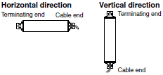
last update: October 15, 2018
OMRON F3SJ Series catalog
F3SJ Series Safety Light Curtain/Catalog- Catalog
- Manual
- CAD
English
Global Edition
| Catalog Name | Catalog Number [size] | Last Update | |
|---|---|---|---|
| | F074-E1-12 [18195KB] | Oct 15, 201820181015 | F3SJ Series Catalog |
OMRON F3SJ Series dimension
F3SJ Series Safety Light Curtain/Dimensionslast update: June 11, 2018
(Unit: mm)
F3SJ-E/F3SJ-B
The dimensions of the F3SJ-E and F3SJ-B are the same except for connector cables and cable leads.
Main Units
Mounting Top/Bottom and Intermediate Brackets
Backside mounting
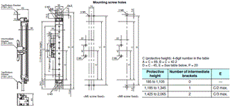
Side mounting
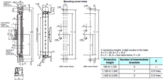
Dimensions of top/bottom bracket for F39-LJB1
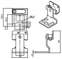
Material: Stainless
Mounting Intermediate Brackets only (location-free mounting)
Backside mounting
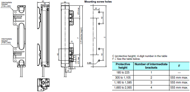
Side mounting
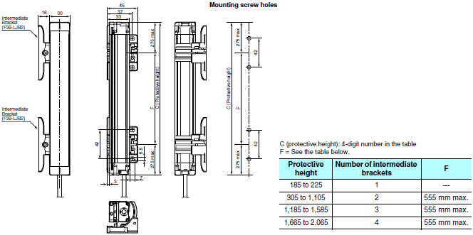
Dimensions of intermediate bracket for F39-LJB2
Backside mounting
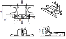
Material : Zinc die-cast
Side mounting
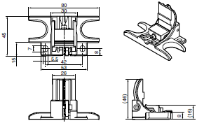
Material : Zinc die-cast
When Using One-touch Brackets
Backside mounting
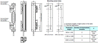
Side mounting
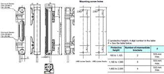
Dimensions of one-touch bracket for F39-LJB3
Backside mounting
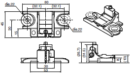
Material : Zinc die-cast
Side mounting
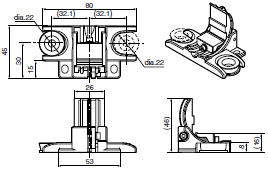
Material : Zinc die-cast
Dimensions of one-touch M6 bracket

Material : Stainless
Dimensions of one-touch M8 bracket

Material : Stainless
When Using Compatible Brackets
Backside mounting
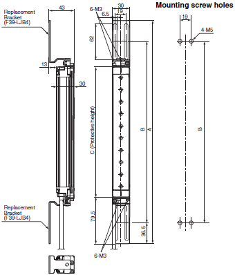
C (protective height): 4-digit number in the Model name
A = C + 159
B = C + 86
Side mounting
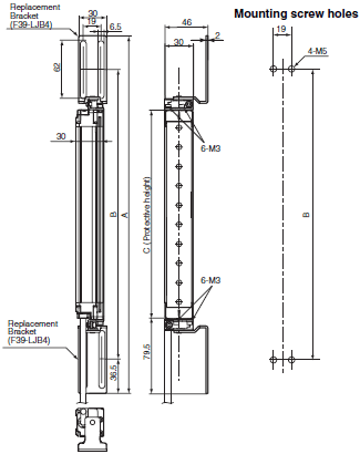
C (protective height): 4-digit number in the Model name
A = C + 159
B = C + 86
Dimensions of compatible bracket for F39-LJB4
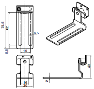
Material: Stainless
When Using Contact Mount Brackets
Backside mounting
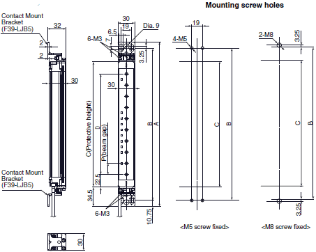
C (protective height): 4-digit number in the Model name
A = C + 69
B = C + 47.5
D = C - 45
Side mounting
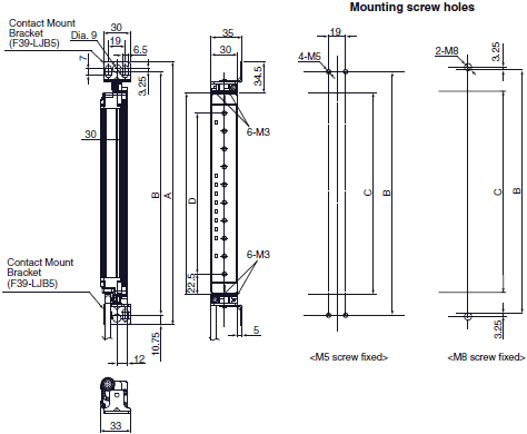
C (protective height): 4-digit number in the Model name
A = C + 69
B = C + 47.5
D = C - 45
Dimensions of F39-LJB5 contact mount bracket
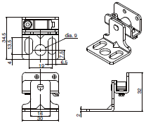
Material: Stainless
Note: 1. The protective height of the F3SJ-E/B series that supports the contact mount bracket is limited.
Protective height allowed for mounting: 185 mm to 1,105 mm (225 mm to 545 mm for the model with the
suffix "-02TS")
2. Brackets of other models such as F39-LJB1 cannot be used simultaneously.
F3SJ-B[][][][]P25-02TS
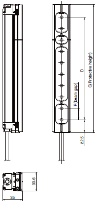
Note: For information on dimensions with brackets mounted, refer to the User's Manual of the F3SJ-B[][][][]P25-02TS
(SCHG-736). Brackets used are common to other F3SJ-E/B series.
Required number of intermediate brackets
The number of the brackets needed for the F3SJ-B[][][][]P25-02TS differs from the other F3SJ-E/B series. The table below shows the number of brackets corresponding to the protective heights.
When using top/bottom bracket/compatible bracket + intermediate bracket

Using only the intermediate bracket (free-location mounting)
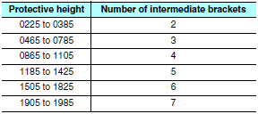
When using the one-touch bracket
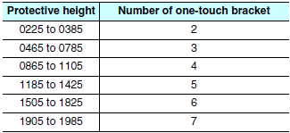
Accessories
Single-Ended Cable (F3SJ-B)
F39-JD3A (L = 3 m)
F39-JD7A (L = 7 m)
F39-JD10A (L = 10 m)
F39-JD15A (L = 15 m)
F39-JD20A (L = 20 m)

Cable color: Gray for emitter and Black for receiver
* Cables with L=3, 7, 10, 15, and 20 m are available.
Double-Ended Cable (F3SJ-B)
F39-JDR5B (L = 0.5 m)
F39-JD1B (L = 1 m)
F39-JD3 (L = 3 m)
F39-JD5 (L = 5 m)
F39-JD7B (L = 7 m)
F39-JD10B (L = 10 m)
F39-JD15B (L = 15 m)
F39-JD20B (L = 20 m)

Cable color: Gray for emitter and Black for receiver
Simple Wiring Connector
F39-CN5
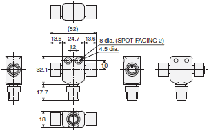
Control Unit (F3SJ-B)
F3SP-B1P
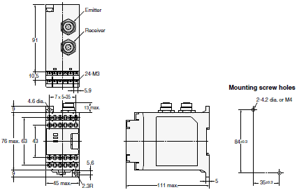
Laser Pointer (F3SJ-E) (F3SJ-B)
F39-PTJ
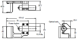
Spatter Protection Cover (F3SJ-E) (F3SJ-B)
F39-HB[][][][]
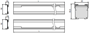
L = [][][][] - 21 mm
Material: PC (protective cover)
Mirrors
F39-MLG[]
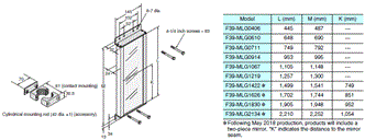
Protective Bar (F3SJ-E) (F3SJ-B)
F39-PB[][][][]
Backside mounting (using M5 screws)
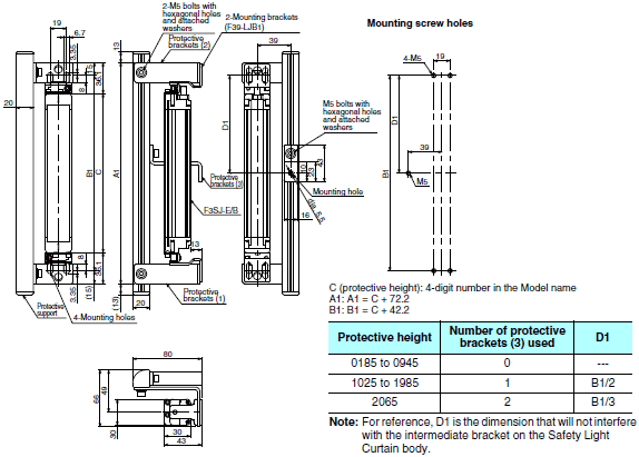
Backside mounting (using M8 screws)
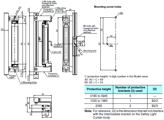
Side mounting (using M5 screws)
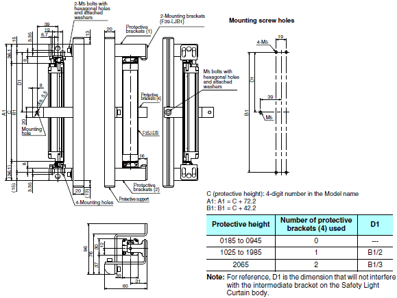
Side mounting (using M8 screws)
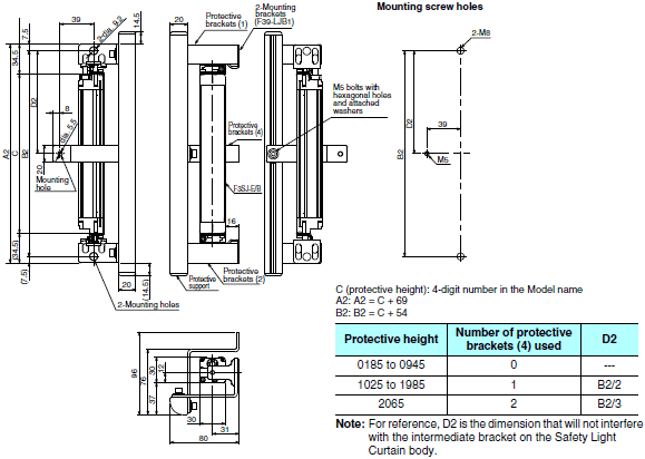
F3SJ-A
Main Units
When Using Standard Mounting Brackets
Backside mounting
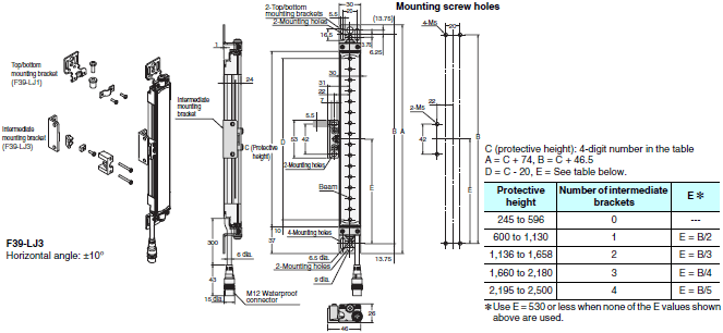
Side mounting
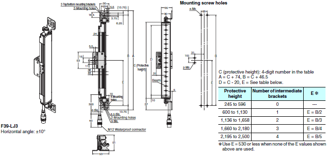
F39-LJ1 Detailed Dimensions of Bracket

Material: Stainless steel

Material: Brass
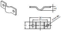
Material: Stainless steel
Using Side Flat Mounting Bracket (F39-LJ2)
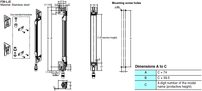
Using Free Location Mounting Bracket (F39-LJ3)
Backside mounting
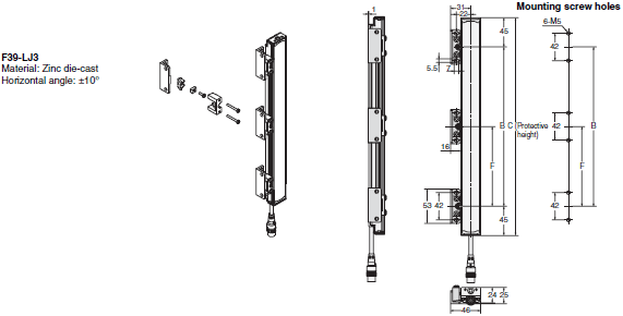
Side mounting
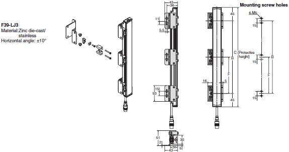
Dimensions B, C, and F

Dimensions F

* Use F = 350 or less when none of the F values shown above are used.
When only F39-LJ3 free-location mounting brackets are used without standard brackets, allow a space of at least 350 mm between the brackets. The number of brackets required varies according to the protective height. For details about the number of required brackets, refer to the table below.
The standard included intermediate brackets are the same as the F39-LJ3 free-location mounting brackets. Purchase brackets as necessary if there are fewer intermediate brackets than required. When intermediate brackets are included, they can be used as free-location mounting brackets.
Required number of F39-LJ3 free-location mounting brackets for 1 F3SJ set (emitter/receiver) (2 pieces are included with F39-LJ3)

Using Top/Bottom Bracket B (F39-LJ4)
Backside mounting
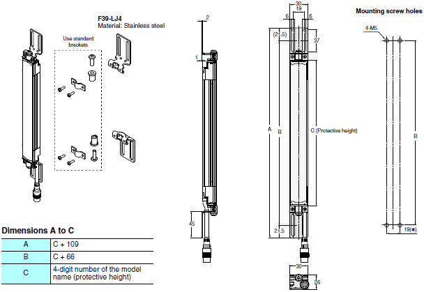
Note: Refer to the User's Manual for the dimensions for side mounting.
* Using M5 bolt, available range for mounting is 18 to 20
Using Top/Bottom Bracket C (F39-LJ11)
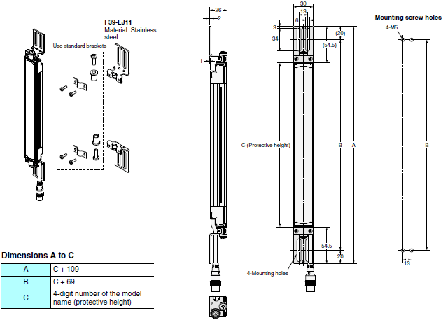
Using Space-saving Mounting Bracket (F39-LJ8)
Backside mounting
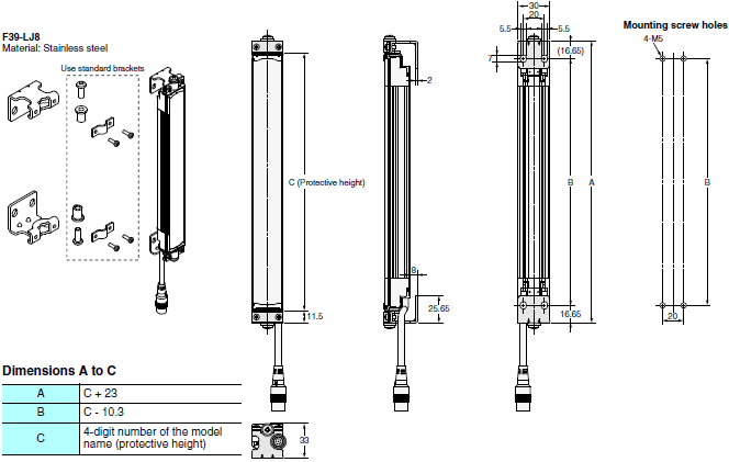
Note:Because the F39-LJ8 cannot be mounted together with an intermediate bracket, keep the protective height at 600
mm max.
Guide to Replacing F3SJ-A with F3SJ-E/B (Including models whose production will be discontinued)
F3SJ-A to F3SJ-E/B replacement correspondence table (F3SJ-A mounting holes can be used without modification)
To check available brackets for replacement, refer to the table below.
To check dimensions when mounting brackets, refer to Catalog.
The values in the table correspond to in the model name, meaning the protective height (mm) of a sensor.
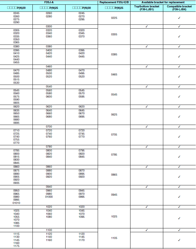
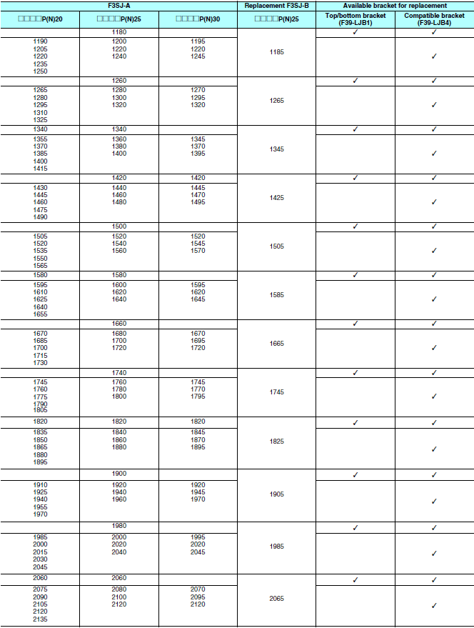
Note: 1. Protective height and detection capability vary according to replacement. Check the safe design of your device
before use.
2. The maximum protective height of F3SJ-E is 1,105 mm. Only the F3SJ-B can be replaced for the protective
height of 1,185 or more.
Change of Dimensions due to Replacement
(1) Replacement by backside mounting

Dimensional drawing from mounting wall surface to optical surface

(2) Replacement by side mounting

Dimensional drawing of a protrusion from mounting wall
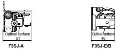
Replacement using intermediate brackets
For backside mounting, the F3SJ-A and F3SJ-E/B can be used without modification due to compatibility in mounting hole pitch. For side mounting, a new hole needs to be made due to the different mounting hole pitch.
Mounting hole pitch for side mounting using intermediate bracket

Dimensional drawing of mounting hole for side mounting using intermediate bracket
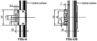
Change of Dimensions due to Replacement

Using mounting bracket for short-length F3SN (F39-LJ5)
Inward-facing mounting
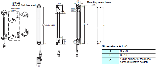
Outward-facing mounting
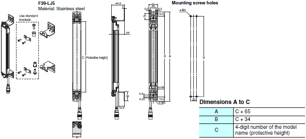
Inward + outward-facing mounting
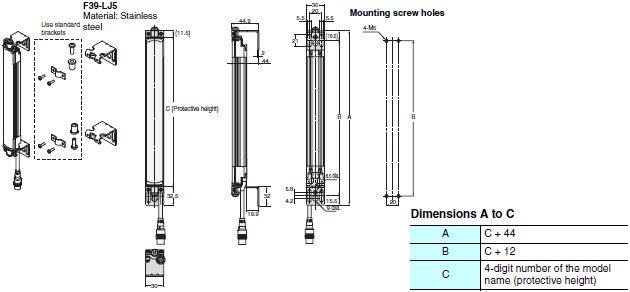
Accessories

Single-Ended Cable
F39-JD3A (L = 3 m)
F39-JD7A (L = 7 m)
F39-JD10A (L = 10 m)
F39-JD15A (L = 15 m)
F39-JD20A (L = 20 m)
Cable color: Gray for emitter Black for receiver
* Cables with L=3, 7, 10, 15, and 20 m are available.

Double-Ended Cable
F39-JDR5B (L = 0.5 m)
F39-JD1B (L = 1 m)
F39-JD3B (L = 3 m)
F39-JD5B (L = 5 m)
F39-JD7B (L = 7 m)
F39-JD10B (L = 10 m)
F39-JD15B (L = 15 m)
F39-JD20B (L = 20 m)
Cable color: Gray for emitter Black for receiver
Simple Wiring Connector
F39-CN5

Control Unit
F3SP-B1P
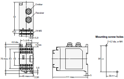
Laser Pointer
F39-PTJ
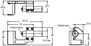
Dedicated External Indicator Set
F39-A01[]-PAC
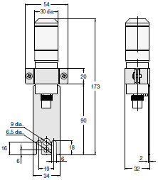
Material: Stainless steel
Spatter Protection Cover
F39-HJ[][][][]

Material: PC (transparent area), ABS (non-transparent area)
Mirrors
F39-MLG[]

Setting Support Software for the F3SJ
F39-GWUM

Protective Bar
F39-PJ[][][][]-S
Backside mounting
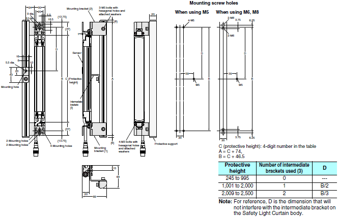
Side mounting
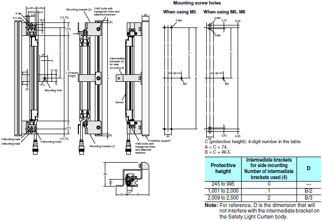
* The four intermediate brackets (F39-PJ-MS) for side mounting are not provided.
Water-resistant Case
F39-EJ[][][][]-L(D)
Backside mounting
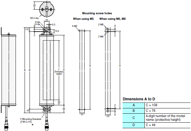
*The Mounting Brackets (F39-EJ-R) are sold separately.
Side mounting
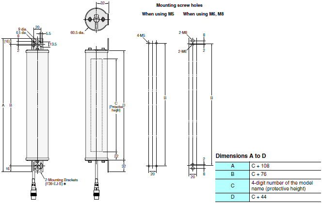
*The Mounting Brackets (F39-EJ-S) are sold separately.
last update: June 11, 2018
- NO. F3SJ Series
- TYPE:Safety Light Curtains / Single-beam Safety Sensors Safety Light Curtains
 Copyright Statement
 - DATE:2021-06-08
- Associated products:
F3W-MA Smart Muting Actuator/Features F3SR-B Safety Light Curtain/Features