OMRON E3Z-LT / LR / LLSensors/ Photoelectric Sensors/Built-in Amplifier
OMRON E3Z-LT / LR / LL Sensors
- E3Z-LT / LR / LL Compact Laser Photoelectric Sensor with Built-in Amplifier/Lineup
- E3Z-LT / LR / LL Compact Laser Photoelectric Sensor with Built-in Amplifier/Catalog
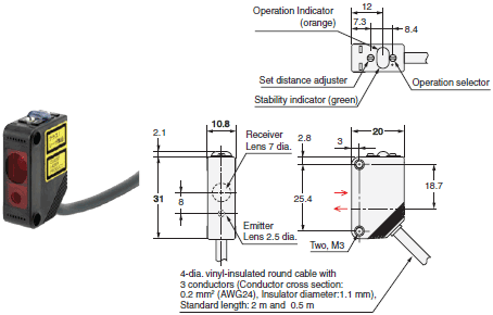
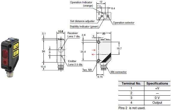
- E3Z-LT / LR / LL Compact Laser Photoelectric Sensor with Built-in Amplifier/Dimensions
- E3Z-LT / LR / LL Compact Laser Photoelectric Sensor with Built-in Amplifier/Specifications
- Purchase the OMRON E3Z-LT / LR / LL Built-in Amplifier
OMRON E3Z-LT / LR / LL Dimensions
/Images/l_1747-25-118750-198x198.jpglast update: December 19, 2013
• Safety and reliability with laser class 1 (JIS and IEC).
• Product lineup includes models with distance setting without influence of color.
• Maximum ambient operating temperature of 55°C and waterproof construction in E3Z class.
last update: December 19, 2013
Purchase the OMRON Built-in Amplifier Please fill in the following
If you have just landed here, this product OMRON E3Z-LT / LR / LL Sensors,Sensors is offered online by Tianin FLD Technical Co.,Ltd. This is an online store providing Sensors at wholesale prices for consumers. You can call us or send enquiry, we would give you the prices, packing,deliverty and more detailed information on the E3Z-LT / LR / LL We cooperate with DHL,TNT,FEDEX,UPS,EMS,etc.They guarantee to meet your needs in terms of time and money,even if you need your OMRON E3Z-LT / LR / LLSensors tomorrow morning (aka overnight or next day air) on your desk, 2, 3 days or more.Note to international customers, YES, we ship worldwide.
CJ1W-NC[][]3 CJ series Position Control Units/Features
G3J-T Soft-start/stop Solid State Contactors/Features
E5AC Digital Temperature Controller (96 x 96 mm)/Features
E5AC-800 Digital Temperature Controller (Simple Type) (96 × 96 mm)/Features
E5ZN Modular Temperature Controller/Features
OMRON E3Z-LT / LR / LL lineup
E3Z-LT / LR / LL Compact Laser Photoelectric Sensor with Built-in Amplifier/Lineuplast update: October 28, 2015
Sensors
| Sensing method | Appearance | Con- nection method | Re- sponse time | Sensing distance (Red light) | Model | |
|---|---|---|---|---|---|---|
| NPN output | PNP output | |||||
| Through- beam (Emitter + Receiver) |  | Pre-wired (2 m) | 1 ms | 60 m | E3Z-LT61 2M Emitter E3Z-LT61-L 2M Receiver E3Z-LT61-D 2M | E3Z-LT81 2M Emitter E3Z-LT81-L 2M Receiver E3Z-LT81-D 2M |
| Connector (M8, 4 pins) | E3Z-LT66 Emitter E3Z-LT66-L Receiver E3Z-LT66-D | E3Z-LT86 Emitter E3Z-LT86-L Receiver E3Z-LT86-D | ||||
| Retro- reflective with MSR function |  | Pre-wired (2 m) | *2 15 m (300 mm) (Using E39-R1) 7 m (200 mm) (Using E39- R12) 7 m (200 mm) (Using E39-R6) | E3Z-LR61 2M | E3Z-LR81 2M | |
| Connector (M8, 4 pins) | E3Z-LR66 | E3Z-LR86 | ||||
| Distance- settable (BGS Models) |  | Pre-wired (2 m) | 20 to 40 mm (Min. distance set) 20 to 300 mm (Max. distance set) | E3Z-LL61 2M | E3Z-LL81 2M | |
| Connector (M8, 4 pins) | E3Z-LL66 | E3Z-LL86 | ||||
| Pre-wired (2 m) | 0.5 ms | 25 to 40 mm (Min. distance set) 25 to 300 mm (Max. distance set) | E3Z-LL63 2M | E3Z-LL83 2M | ||
| Connector (M8, 4 pins) | E3Z-LL68 | E3Z-LL88 | ||||
*1. The Reflector is sold separately. Select the Reflector model most suited to the application.
*2. Values in parentheses indicate the minimum required distance between the Sensor and Reflector.
Accessories
Slits
(A Slit is not provided with a Through-beam Sensor. Order a Slit separately if required.)
| Slit width | Sensing distance | Minimum detectable object (reference value) | Model | Contents |
|---|---|---|---|---|
| 0.5 mm dia. | 3 m | 0.1 mm dia. | E39-S65A | One set (contains Slits for both the Emitter and Receiver) |
Reflectors
(A Reflector is required for each Retro-reflective Sensor: A Reflector is not provided with the Sensor. Be sure to order a Reflector.)
| Name | Sensing distance | Model | Remarks | |
|---|---|---|---|---|
| Rated value | Reference value | |||
| Reflector | --- | 15 m (300 mm) | E39-R1 | Retro-reflective models are not provided with Reflectors. Separate the Sensor and the Reflector by at least the distance given in parentheses. The MSR function is enabled. |
| 7 m (200 mm) | --- | E39-R12 | ||
| --- | 7 m (200 mm) | E39-R6 | ||
Note: If you use the Reflector at any distance other than the rated distance, make sure that the stability indicator lights
properly when you install the Sensor.
Mounting Brackets
A Mounting Bracket is not provided with the Sensor. Order a Mounting Bracket separately if required.
| Appearance | Model | Quantity | Remarks |
|---|---|---|---|
 | E39-L153 *1 | 1 | Mounting Brackets |
 | E39-L104 *1 | 1 | |
 | E39-L43 *2 | 1 | Horizontal Mounting Bracket |
 | E39-L142 *2 | 1 | Horizontal Protective Cover Bracket |
 | E39-L44 | 1 | Rear Mounting Bracket |
 | E39-L98 *2 | 1 | Metal Protective Cover Bracket |
 | E39-L150 | 1 set | (Sensor adjuster) Easily mounted to the aluminum frame rails of conveyors and easily adjusted. For left to right adjustment |
 | E39-L151 | 1 set | |
 | E39-L144 *2 | 1 | Compact Protective Cover Bracket (For E3Z only) |
Note: When using a Through-beam Sensor, order one Mounting Bracket for the Receiver and one for the Emitter
*1. Cannot be used for Standard Connector models with mounting surface on the bottom. In that case, use Pre-wired
Connector models.
*2. Cannot be used for Standard Connector models.
Sensor I/O Connectors (Sockets on One Cable End)
(Models for Connectors and Pre-wired Connectors: A Connector is not provided with the Sensor. Be sure to order a Connector separately.)
| Size | Cable | Appearance | Cable type | Model | ||
|---|---|---|---|---|---|---|
| M8 | Standard | Straight *1 |  | 2 m | 4-wire | XS3F-M421-402-A |
| 5 m | XS3F-M421-405-A | |||||
| L-shaped *1 *2 |  | 2 m | XS3F-M422-402-A | |||
| 5 m | XS3F-M422-405-A | |||||
Note: When using a Through-beam Sensor, order one Mounting Bracket for the Receiver and one for the Emitter
*1. The connector will not rotate after connecting.
*2. The cable is fixed at an angle of 180° from the sensor emitter/receiver surface.
last update: October 28, 2015
OMRON E3Z-LT / LR / LL catalog
E3Z-LT / LR / LL Compact Laser Photoelectric Sensor with Built-in Amplifier/Catalog- Catalog
- Manual
- CAD
English
Global Edition
| Catalog Name | Catalog Number [size] | Last Update | |
|---|---|---|---|
| | - [2235KB] | Oct 28, 201520151028 | E3Z-LT/LR/LL Data Sheet |
OMRON E3Z-LT / LR / LL dimension
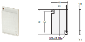
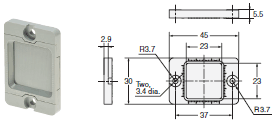
E3Z-LT / LR / LL Compact Laser Photoelectric Sensor with Built-in Amplifier/Dimensionslast update: November 15, 2012
Tolerance class IT16 applies to dimensions in this datasheet unless otherwise specified.
Sensors
Through-beam *
Pre-wired Models
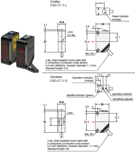
E3Z-LT61, E3Z-LT81
Through-beam *
Standard Connector Models
E3Z-LT66, E3Z-LT86
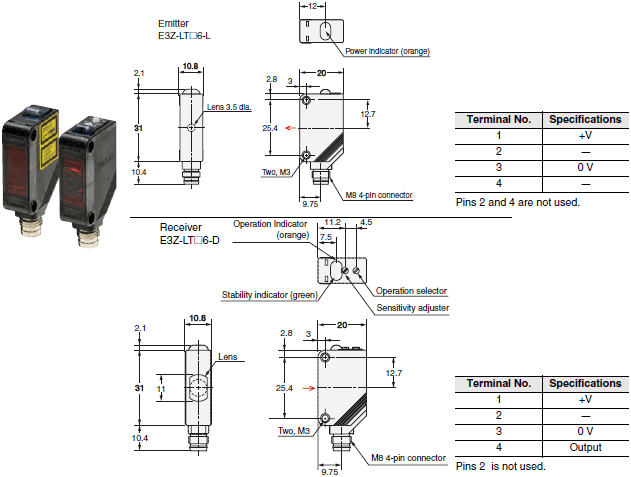
* Models numbers for Through-beam Sensors (E3Z-LT[][]) are for sets that include both the Emitter and Receiver.
The model number of the Emitter is expressed by adding "-L" to the set model number (example: E3Z-LT61-L 2M),
the model number of the Receiver, by adding "-D" (example: E3Z-LT61-D 2M.) Refer to Ordering Information to
confirm model numbers for Emitter and Receivers.
Retro-reflective Models
Pre-wired Models
E3Z-LR61, E3Z-LR81
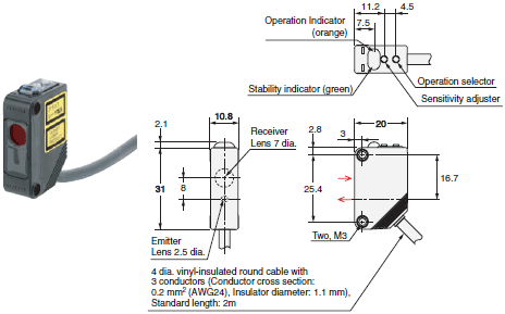
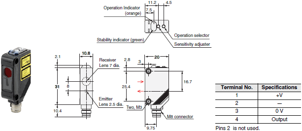
Retro-reflective Models
Standard Connector Models
E3Z-LR66, E3Z-LR86
BGS Models
Pre-wired Models
E3Z-LL61, E3Z-LL81
E3Z-LL63, E3Z-LL83
BGS Models
Standard M8 Connector Models
E3Z-LL66, E3Z-LL86
E3Z-LL68, E3Z-LL88
Accessories (Order Separately)
Slit
E39-S65A
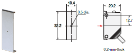
Material
SUS301 stainless steel
Reflector
E39-R1
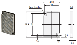
MaterialsReflective surface: AcrylicRear surface: ABS
Reflector
E39-R6
MaterialsReflective surface: AcrylicRear surface: ABS
Reflector
E39-R12
Note:Materials
Reflector: Polycarbonate (surface), Acrylic (interior)
Frame: ABS
last update: November 15, 2012
OMRON E3Z-LT / LR / LL specification
E3Z-LT / LR / LL Compact Laser Photoelectric Sensor with Built-in Amplifier/Specificationslast update: October 28, 2015
| Sensing method | Through-beam | Retro-reflective with MSR function | Distance-settable (BGS models) | ||
|---|---|---|---|---|---|
| Response | Standard response | High-speed response | |||
| Model | NPN output | E3Z-LT61/-LT66 | E3Z-LR61/-LR66 | E3Z-LL61/-LL66 | E3Z-LL63/-LL68 |
| PNP output | E3Z-LT81/-LT86 | E3Z-LR81/-LR86 | E3Z-LL81/-LL86 | E3Z-LL83/-LL88 | |
| Sensing distance | 60 m | 0.2 to 7 m (when using E39-R12) | White paper (100 × 100 mm): 20 to 300 mm Black paper (100 × 100 mm): 20 to 160 mm | White paper (100 × 100 mm): 25 to 300 mm Black paper (100 × 100 mm): 25 to 100 mm | |
| Set distance range | --- | White paper (100 × 100 mm): 40 to 300 mm Black paper (100 × 100 mm): 40 to 160 mm | White paper (100 × 100 mm): 40 to 300 mm Black paper (100 × 100 mm): 40 to 100 mm | ||
| Spot diameter (reference value) | 5-mm dia. at 3 m | 0.5-mm dia. at 300 mm | |||
| Standard sensing object | Opaque: 12-mm dia. min. | Opaque: 75-mm dia. min. | --- | ||
| Minimum detectable object (reference value) | 6-mm-dia. opaque object at 3 m | 0.2-mm-dia. stainless-steel pin gauge at 300 mm | |||
| Differential travel | --- | 5% max. of set distance | |||
| Black/white error | --- | 5% at 160 mm | 5% at 100 mm | ||
| Directional angle | Receiver: 3 to 15° | --- | |||
| Light source (wavelength) | Red LD (655 nm), JIS CLass 1, IEC Class 1, FDA Class 2 | ||||
| Power supply voltage | 12 to 24 VDC±10%, ripple (p-p): 10% max. | ||||
| Current consumption | 35 mA (Emitter 15 mA, Receiver 20 mA) | 30 mA max. | |||
| Control output | Load power supply voltage: 26.4 VDC max., Load current: 100 mA max., Open collector output | ||||
| Residual output voltage | Load current of less than 10 mA: 1 V max. Load current of 10 to 100 mA: 2 V max. | ||||
| Output mode switching | Switch to change between light-ON and dark-ON | ||||
| Protection circuits | Reversed power supply polarity protection, Output short-circuit protection, and Reversed output polarity protection | Reversed power supply polarity protection, Output short-circuit protection, Mutual interference prevention, and Reversed output polarity protection | |||
| Response time | Operate or reset: 1 ms max. | Operate or reset: 0.5 ms max. | |||
| Sensitivity adjustment | One-turn adjuster | Five-turn endless adjuster | |||
| Ambient illumination (Receiver side) | Incandescent lamp: 3,000 lx max. Sunlight: 10,000 lx max. | ||||
| Ambient temperature range | Operating: -10 to 55°C, Storage: -25 to 70°C (with no icing or condensation) | ||||
| Ambient humidity range | Operating: 35% to 85%, Storage: 35% to 95% (with no icing or condensation) | ||||
| Insulation resistance | 20 MΩ min. at 500 VDC | ||||
| Dielectric strength | 1,000 VAC, 50/60 Hz for 1 min | ||||
| Vibration resistance | Destruction: 10 to 55 Hz, 1.5-mm double amplitude for 2 hours each in X, Y, and Z directions | ||||
| Shock resistance | Destruction: 500 m/s2 3 times each in X, Y, and Z directions | ||||
| Degree of protection | IP67 (IEC 60529) | ||||
| Connection method | Pre-wired cable (standard length: 2 m): E3Z-L[][]1/-L[][]3 Standard M8 Connector: E3Z-L[][]6/-L[][]8 | ||||
| Indicator | Operation indicator (orange) Stability indicator (green) Emitter for Through-bream Models has power indicator (orange) only. | ||||
| Weight (packed state) | Pre-wired cable (2 m) | Approx. 120 g | Approx. 65 g | ||
| Standard Connector | Approx. 30 g | Approx. 20 g | |||
| Material | Case | PBT (polybutylene terephthalate) | |||
| Lens | Modified polyarylate resin | Methacrylic resin | Modified polyarylate resin | ||
| Accessories | Instruction manual (Neither Reflectors nor Mounting Brackets are provided with any of the above models.) | ||||
last update: October 28, 2015
- NO. E3Z-LT / LR / LL
- TYPE:Photoelectric Sensors Built-in Amplifier
 Copyright Statement
 - DATE:2021-06-18
- Associated products:
E3ZM Compact Photoelectric Sensor with Stainless Steel Housing/Features E3Z-LS Distance-settable Photoelectric Sensor/Features