OMRON E5ZNControl Components/ Temperature Controllers/Module Type
OMRON E5ZN Control Components
OMRON E5ZN Dimensions
/Images/l_171-25-118780-198x198.jpglast update: December 19, 2013
• Two channels of temperature control available despite width of only 22.5 mm.
• The Temperature Controller itself can be replaced without changing terminal wiring.
• Use in combination with a compact Setting Display Unit to reduce communications programming requirements.
• Front-panel LED indicators for easy operation monitoring.
• Power supply and communications wiring not required between Units when mounted side-by-side.
• CompoWay/F communications protocol supported.
• UL, CSA, and CE Marking compliance.
last update: December 19, 2013
Purchase the OMRON Module Type Please fill in the following
If you have just landed here, this product OMRON E5ZN Control Components,Control Components is offered online by Tianin FLD Technical Co.,Ltd. This is an online store providing Control Components at wholesale prices for consumers. You can call us or send enquiry, we would give you the prices, packing,deliverty and more detailed information on the E5ZN We cooperate with DHL,TNT,FEDEX,UPS,EMS,etc.They guarantee to meet your needs in terms of time and money,even if you need your OMRON E5ZNControl Components tomorrow morning (aka overnight or next day air) on your desk, 2, 3 days or more.Note to international customers, YES, we ship worldwide.
Z4W-V LED Displacement Sensor/Features
D5V Contact Displacement Sensor/Features
EE-SPX301 / 401, EE-SPY30 / 40 Slot-type Reflective Photomicrosensor/Features
E58-CIFQ1 USB-Serial Conversion Cable/Features
GX-AD0471 / DA0271 Analog I/O Terminal 2-tier Terminal Block Type/Features
OMRON E5ZN lineup
E5ZN Modular Temperature Controller/Lineuplast update: April 3, 2017
| Name | Power supply | No. of con- trol points | Control output | Auxiliary output | Functions | Com- muni- cations functions | Input type *5 | Model | |
|---|---|---|---|---|---|---|---|---|---|
| Tem- pera- ture Con- troller *1 | 24 VDC | 2 | Voltage output (for SSRs) | Transistor output: 2 pts (sinking) | Heater burnout alarm *3 | Heating or heat/ cool control is se- lectable *4 Event input: 1 point per Unit | RS-485 | Thermocouple | E5ZN-2QNH03TC-FLK |
| Platinum resistance thermometer | E5ZN-2QNH03P-FLK | ||||||||
| Transistor output: 2 pts (sourcing) | Thermocouple | E5ZN-2QPH03TC-FLK | |||||||
| Platinum resistance thermometer | E5ZN-2QPH03P-FLK | ||||||||
| Tran- sistor output | Transistor output: 2 pts (sinking) | Thermocouple | E5ZN-2TNH03TC-FLK | ||||||
| Platinum resistance thermometer | E5ZN-2TNH03P-FLK | ||||||||
| Transistor output: 2 pts (sourcing) | Thermocouple | E5ZN-2TPH03TC-FLK | |||||||
| Platinum resistance thermometer | E5ZN-2TPH03P-FLK | ||||||||
| Analog output (current output) *2 | Transistor output: 2 pts (sinking) | Transfer out-put (linear voltage out-put) *2 | Thermocouple | E5ZN-2CNF03TC-FLK | |||||
| Platinum resistance thermometer | E5ZN-2CNF03P-FLK | ||||||||
| Transistor output: 2 pts (sourcing) | Thermocouple | E5ZN-2CPF03TC-FLK | |||||||
| Platinum resistance thermometer | E5ZN-2CPF03P-FLK | ||||||||
*1. Terminal Units are required for wiring. Purchase separately.
*2. When connecting the load of the controlled system, heat control output or cool control output can be allocated to the
control output or auxiliary output. When connecting a recording device or Digital Panel Meter, transfer output can be
allocated to control output or auxiliary output 3 or 4 of analog output models.
*3. When using the heater burnout alarm, purchase a Current Transformer (E54-CT1 or E54-CT3) separately.
*4. When using heating and cooling control functionality, the auxiliary output will be either heating control output or cooling
control output.
*5. Analog input and infrared temperature sensors (ES1B) can also be used with thermocouple models.
Terminal Unit
| Name | No. of terminals | Functions | Model |
|---|---|---|---|
| Terminal Unit (Includes bus system without backplane.) | 24 | Equipped with communications terminals for power supply, communications, and setting devices. | E5ZN-SCT24S-500 |
| 18 *1 | Not equipped with communications terminals for power supply, communications, and setting devices. | E5ZN-SCT18S-500 |
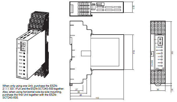
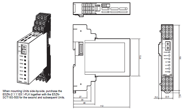
*1. When using 2 or more E5ZNs mounted side-by-side, use the E5ZN-SCT18S-500 for the second and subsequent
Units. When using E5ZNs separately, be sure to use the E5ZN-SCT24S-500.
*2. Two End Plates are provided with a E5ZN-SCT24S-500 Terminal Unit. Up to 16 Terminal Units can be used to expand
the system to a maximum of 32 channels. When mounting to a DIN Track, be sure to mount End Plates on both sides.
Accessories (Order Separately)
Terminal Cover
| Model | E53-COV12 | E53-COV13 |
|---|---|---|
| Type | For SCT24S-500 models | For SCT18S-500 models |
Current Transformer (CT)
| Model | E54-CT1 | E54-CT3 |
|---|---|---|
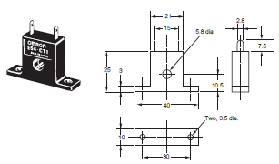
| Diameter | 5.8 dia. | 12.0 dia. |
Setting Display Unit
| Name | Power supply | Model |
|---|---|---|
| Setting Display Unit (See note.) | 24 VDC | E5ZN-SDL * |
* Production was discontinued.
Note: Purchase sockets for wiring (shown on below) separately.
Sockets (for Setting Display Unit - Order Separately)
| Model | P2CF-11 | P2CF-11-E | P3GA-11 | Y92A-48G |
|---|---|---|---|---|
| Type | Front-connecting socket | Front-connecting socket (with finger protection) | Back-connecting socket | Terminal cover for finger protection |
last update: April 3, 2017
OMRON E5ZN dimension
E5ZN Modular Temperature Controller/Dimensionslast update: April 3, 2017
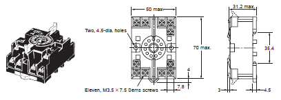
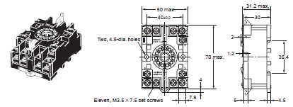
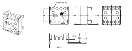
(Unit: mm)
E5ZN-2[][][][]03[]-FLK Connected to E5ZN-SCT24S-500
E5ZN-2[][][]03[]-FLK Connected to E5ZN-SCT18S-500
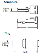
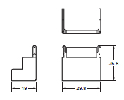
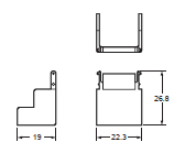
Current Transformer (Order Separately)
E54-CT1
E54-CT3
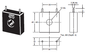
E54-CT3 Accessories
Terminal Cover (Order Separately)
E53-COV12
E53-COV13
Setting Display Unit
E5ZN-SDL *
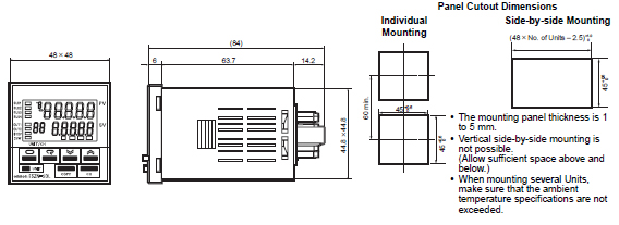
* Production was discontinued.
E5ZN-SDL Wiring Sockets
Front-connecting Sockets
P2CF-11 (Standard Model)
P2F-11-E (with Finger Protection)
Back-connecting Sockets
P3GA-11 (Standard Model)
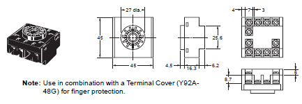
Terminal Cover
Y92A-48G
last update: April 3, 2017
OMRON E5ZN specification
E5ZN Modular Temperature Controller/Specificationslast update: April 3, 2017
Ratings
| Power supply voltage | 24 VDC | ||
|---|---|---|---|
| Allowable voltage range | 85% to 110% of the rated power supply voltage | ||
| Power consumption | Approx. 3 W | ||
| Sensor input | Thermocouple: K, J, T, E, L, U, N, R, S, B Infrared temperature sensor (ES1B series): 10 to 70°C, 60 to 120°C, 115 to 165°C, 140 to 260°C Voltage input: 0 to 50 mV | ||
| Platinum resistance thermometer: Pt100, JPt100 | |||
| Control output | Voltage output (for driving SSR) | Output voltage: 12 VDC ±15% (PNP); Maximum load current: 21 mA; Equipped with short-circuit protection circuit | |
| Transistor output | Maximum operational voltage: 30 VDC; Maximum load current: 100 mA; Residual voltage: 1.5 V max.; Leakage current: 0.4 mA max. | ||
| Current output | Current output range: 4 to 20/0 to 20 mA DC; Load: 350 Ω max. (See note 2.) | ||
| Auxiliary output | Transistor output | Sourcing | Maximum operating voltage: 30 VDC; Maximum load current: 50 mA; Residual voltage: 1.5 V max.; Leakage current: 0.4 mA max. |
| Sinking | |||
| Linear voltage output | Voltage output range: 1 to 5/0 to 5 VDC; Load: 10 kΩ min. | ||
| Event input | Contact output | ON: 1 kΩ max., OFF: 100 kΩ min. Discharge current: Approx. 7 mA | |
| Non-contact output | ON: Residual voltage: 1.5 V max., OFF: Leakage current: 0.1 mA max. Discharge current: Approx. 7 mA | ||
| Number of input and control points | Input points: 2, Control points: 2 | ||
| Setting method | Via communications or using the Setting Display Unit (E5ZN-SDL *) | ||
| Control method | 2-PID or ON/OFF control | ||
| Other functions | Heater burnout detection function, transfer output function Multi-SP and RUN/STOP switching using event input | ||
| Ambient operating temperature | -10 to 55℃ (with no icing or condensation) For 3 years of assured use: -10 to 50℃ | ||
| Ambient operating humidity | 25% to 85% | ||
| Storage temperature | -25 to 65℃ (with no icing or condensation) | ||
* Production was discontinued.
Note: 1. Do not use an inverter output for the power supply. (Refer to Safety Precautions for All Temperature Controllers.)
2. OMRON G32A-EA Cycle Controller Unit (load impedance 352 Ω) can be used.
Input Range
Platinum Resistance Thermometer Models and Thermocouple Models
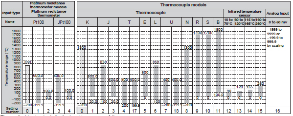
The applicable standards for the input types are as follows:
• K, J, T, E, N, R, S, B: JIS C1602-1995, IEC584-1
• L: Fe-CuNi, DIN 43710-1985
• U: Cu-CuNi, DIN 43710-1985
• JPt100: JIS C 1604-1989, JIS C 1606-1989
• Pt100: JIS C 1604-1997 IEC 751
Shaded parts indicate the settings at the time of purchase.
Characteristics
| Indication accuracy | Thermocouple: (Indicated value ±0.5% or ±1℃, whichever is greater) ±1 digit max. *1 Platinum resistance thermometer: (Indicated value ±0.5% or ±1℃, whichever is greater) ±1 digit max. *1 Analog input: ±0.5% or ±1 digit max. CT input: ±5% FS ±1 digit max. |
|---|---|
| Influence of temperature | Thermocouple input (R, S, B): (±1% of PV or ±10℃, whichever is greater) ±1 digit max. Other thermocouple input: ( ±1% of PV or ±4℃, whichever is greater) ±1 digit max. *K thermocouple at -100℃ max.: ±10℃ max. Platinum resistance thermometer: (±1% of PV or ±2℃, whichever is greater) ±1 digit max. Analog input: (±1%FS) ±1 digit max. |
| Influence of voltage | |
| Transfer output | Accuracy: ±0.5% FS *2 |
| Hysteresis | 0.1 to 999.9 EU (in units of 0.1 EU) *3 |
| Proportional band (P) | 0.1 to 999.9 EU (in units of 0.1 EU) *3 |
| Integral time (I) | 0 to 3,999 s (in units of 1 s) |
| Derivative time (D) | 0 to 3,999 s (in units of 1 s) |
| Control period | 1 to 99 s (in units of 1 s) |
| Manual reset value | 0.0 to 100.0% (in units of 0.1%) |
| Alarm setting range | -1,999 to 9,999 (Position of decimal point depends on input type.) |
| Sampling period | 500 ms |
| Insulation resistance | 20 MΩ min. (at 500 VDC) |
| Dielectric strength | 600 VAC for 1 minute at 50 or 60 Hz (between unlike terminals of charged parts) |
| Vibration resistance | 10 to 55 Hz, 10 m/s2 for 2 h each in X, Y, and Z directions |
| Shock resistance | 150 m/s2 max., 3 times each in ±X, ±Y, and ±Z directions |
| Weight | Temperature Controller: Approx. 90 g Terminal Unit (18): Approx. 80 g Terminal Unit (24): Approx. 100 g |
| Degree of protection | Temperature Controller: IP00 Terminal Unit: IP00 |
| Memory protection | EEPROM (non-volatile memory) (Number of write operations: 100,000) |
| Approved standards *4 | UL File No.: E200593 CSA File No.: 203889-1140084 CE EMS: ESD EN61326, EN61000-4-2 (4 kV/contact, 8 kV/air) REM field EN61326, EN61000-4-3 (10 V/m) Fast transient EN61326, EN61000-4-4 (2 kV/DC power, 1 kV/I/O) Surge immunity EN61326, EN61000-4-5 (line to ground: 2 kV/DC power 1 kV/I/O, line to line: 1 kV/DC power) Conducted RF EN61326, EN61000-4-6 (10 V) EMI: Radiated EN61326 Class A |
*1. The indication accuracy for T and N thermocouples at −100°C, and for U and L thermocouples is ±2°C ±1 digit max.
There is no specification for the indication accuracy for the B thermocouple used at 400°C max. The indication
accuracy for R and S thermocouples at 200°C max. is ±3°C ±1 digit max.
*2. The transfer output accuracy for 0 to 4 mA when 0 to 20 mA DC is selected is ±0.5% FS +0.7 mA. The transfer output
accuracy for 0 to 1 V when 0 to 5 VDC is selected is ±0.5% FS +0.175 V.
*3. "EU" stands for "Engineering Unit."
*4. In order to satisfy the EN61326 Class A standard for conducted emissions, install a noise filter (Densei-Lambda MXB-
1206-33 or equivalent) in a DC power line as close to the E5ZN as possible.
Communications (Host Communications)
| Transmission line connection method | RS-485 multipoint |
|---|---|
| Communications method | RS-485 (2-wire, half-duplex) |
| Synchronization method | Start-stop synchronization |
| Baud rate | 4,800, 9,600, 19,200, or 38,400 bps |
| Transmission code | ASCII |
| Data bit length * | 7 or 8 bits |
| Stop bit length * | 1 or 2 bits |
| Error detection | Vertical parity (none, even, odd) |
| BCC (block check character) | |
| Flow control | None |
| Interface | RS-485 |
| Retry function | None |
| Number of Units that can be connected in parallel | 16 Units max. (32 channels) |
* The baud rate, data bit length, stop bit length, and vertical parity can all be set independently as host communications
settings.
: Default setting values
Current Transformer (CT) (Order Separately)
| Dielectric strength | 1,000 VAC (1 minute) |
|---|---|
| Vibration resistance | 50 Hz, 98 m/s2 |
| Weight | E54-CT1: Approx. 11.5 g E54-CT3: Approx. 50 g |
| Accessories (E54-CT3 only) | Armature (2) Plug (2) |
Heater Burnout Alarm
| Maximum heater current | Single-phase, 50 A AC *1 |
|---|---|
| Input current readout accuracy | ±5% FS ±1 digit max. |
| Heater burnout alarm setting range | 0.0 to 50.0 A (in units of 0.1 A) *2 |
| Minimum detection ON time | 190 ms *3 |
*1. Use the K8AC-H Digital Heater Burnout Alarm Detector for burnout detection of 3-phase heaters.
*2. If the heater burnout alarm setting is set to 0.0 A, the alarm is always OFF, and if it is set to 50.0 A the alarm is
always ON.
*3. If the ON time for control output is less than 190 ms, heater burnout detection and heater current measurement will
not be performed.
Setting Display Unit (Order Separately)
| Power supply voltage | 24 VDC |
|---|---|
| Allowable voltage range | 85% to 110% of the rated power supply voltage |
| Power consumption | Approx. 1 W |
| Display method | 7-segment digital display and single-color display |
| Ambient operating temperature | -10 to 55 ℃ (with no icing or condensation) For 3 years of assured use: -10 to 50 ℃ |
| Ambient operating humidity | 25% to 85% |
| Storage temperature | -25 to 65 ℃ (with no icing or condensation) |
| Communications method | RS-485 (half-duplex) |
| Communications format | Special protocol |
| Insulation resistance | 20 MΩ min. (at 500 VDC) |
| Dielectric strength | 1,500 VAC for 1 minute at 50 or 60 Hz (between unlike terminals of charged parts) |
| Vibration resistance | 10 to 55 Hz, 20 m/s2 for 2 h each in X, Y, and Z directions |
| Shock resistance | 300 m/s2 max., 3 times each in ±X, ±Y, and ±Z directions |
| Enclosure ratings | Front panel: IP50 Rear case: IP20 Terminal case: IP00 |
| Memory protection | EEPROM (non-volatile memory) (Number of writes: 100,000) |
| Weight | Approx. 100 g Mounting bracket: Approx. 10 g |
last update: April 3, 2017
OMRON E5ZN catalog
E5ZN Modular Temperature Controller/Catalog- Catalog
- Manual
- CAD
English
Global Edition
| Catalog Name | Catalog Number [size] | Last Update | |
|---|---|---|---|
| | - [1641KB] | Apr 03, 201720170403 | E5ZN Data Sheet |
| | [1325KB] | Apr 02, 201820180402 | E5ZN Operation |
- NO. E5ZN
- TYPE:Temperature Controllers Module Type
 Copyright Statement
 - DATE:2021-06-08
- Associated products:
EJ1 Modular Temperature Controller/Features E5ZN-DRT DeviceNet Communications Unit/Features