OMRON CS1W-CRM21Automation Systems/ Networks/CompoNet
OMRON CS1W-CRM21 Automation Systems
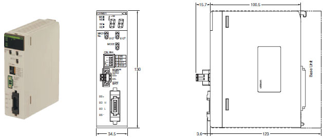
OMRON CS1W-CRM21 Dimensions
/Images/l_1781-25-118625-198x198.jpglast update: December 19, 2013
• Setup is simple. Make the master's mode settings and set the baud rate, and you're ready to go.
• Control up to 2,560 points and 384 nodes with one Master Unit.
• Intuitive memory mapping with separate areas for Word Slave Units and Bit Slave Units.
• Seven-segment display helps with startup and enables prompt detection of problems.
• Collect information from Slave Units using message communications, or use message communications to set parameters.
• Inherits the ease of use of the CompoBus/S.
• Flexible I/O allocations with software setting function.
last update: December 19, 2013
Purchase the OMRON CompoNet Please fill in the following
If you have just landed here, this product OMRON CS1W-CRM21 Automation Systems,Automation Systems is offered online by Tianin FLD Technical Co.,Ltd. This is an online store providing Automation Systems at wholesale prices for consumers. You can call us or send enquiry, we would give you the prices, packing,deliverty and more detailed information on the CS1W-CRM21 We cooperate with DHL,TNT,FEDEX,UPS,EMS,etc.They guarantee to meet your needs in terms of time and money,even if you need your OMRON CS1W-CRM21Automation Systems tomorrow morning (aka overnight or next day air) on your desk, 2, 3 days or more.Note to international customers, YES, we ship worldwide.
ZX-L-N Smart Sensors (Laser Displacement & Measurement Sensors)/Features
1ZAP2 / 1VAP2 Door Switches/Features
NX-AD / DA NX-series Analog I/O Unit/Features
DRT2-AD04(H) / DA02 Analog I/O Terminals/Features
K8AK-PW Three-phase Voltage Relay/Features
OMRON CS1W-CRM21 dimension
CS1W-CRM21 CS-series CompoNet Master Units/Dimensionslast update: November 02, 2012
CS1W-CRM21
last update: November 02, 2012
OMRON CS1W-CRM21 lineup
CS1W-CRM21 CS-series CompoNet Master Units/Lineuplast update: May 11, 2016
International Standards
- The standards are abbreviated as follows: U: UL, U1: UL(Class I Division 2 Products for Hazardous Locations), C: CSA, UC: cULus, UC1: cULus (Class I Division 2 Products for Hazardous Locations), CU: cUL, N: NK, L: Lloyd, and CE: EC Directives.
- Contact your OMRON representative for further details and applicable conditions for these standards.
| Name | Appear- ance | Specifications | Number of unit numbers allocated | Power consumption (A) | Model | Stand- ards | ||
|---|---|---|---|---|---|---|---|---|
| Type of com- munications | Maximum number of I/O points per Master Unit | 5-V system | 26-V system | |||||
| CS1 Special I/O Unit |  | Remote I/O communications Message communications | Word Slave Units: 1,024 inputs and 1,024 outputs (2,048 I/O points total) Bit Slave Units: 256 inputs and 256 outputs (512 I/O points total) | 1, 2, 4, or 8 | 0.4 | - | CS1W-CRM21 | CE, U, U1, L, N |
| Product name | Specifications | Model | Stand- ards | ||
|---|---|---|---|---|---|
| Number of licenses | Media | ||||
| CX-One FA Integrated Tool Package Ver. 4.[] | The CX-One is a package that integrates the Support Software for OMRON PLCs and components. CX-One runs on the following OS. Note: Windows XP (Service Pack 3 or higher, 32-bit version)/Windows Vista (32-bit/64-bit version)/Windows 7 (32-bit/64-bit version)/ Windows 8 (32-bit/64-bit version)/ Windows 8.1(32-bit/64-bit version)/ Windows 10 (32-bit/64-bit version) CX-One Ver. 4.[] includes CX-Integrator Ver. 2.[]. For details, refer to the CX-One catalog (Cat. No. R134). | 1 license * | DVD | CXONE-AL01D-V4 | - |
* Multi licenses (3, 10, 30, or 50 licenses) and DVD media without licenses are also available for the CX-One.
last update: May 11, 2016
OMRON CS1W-CRM21 catalog
CS1W-CRM21 CS-series CompoNet Master Units/Catalog- Catalog
- Manual
- CAD
English
Global Edition
| Catalog Name | Catalog Number [size] | Last Update | |
|---|---|---|---|
| | - [725KB] | May 11, 201620160511 | CS1W-CRM21 Data Sheet |
OMRON CS1W-CRM21 specification
CS1W-CRM21 CS-series CompoNet Master Units/Specificationslast update: October 18, 2012
Communication Specifications
| Item | Specification | |
| Communications protocol | CompoNet Network protocol | |
| Types of communications | Remote I/ communications ( communications as required with PLCs) | |
| Baud rate | 4 Mbits/ | |
| Modulation | Base- | |
| Coding | Manchester code | |
| Error control | Manchester code rules, | |
| Communications media | The following media can be used. Round cable I ( Round cable II ( Flat Cable I ( Flat Cable II ( | |
| Communications distance and wiring | Refer to Cable Types, | |
| Connectable Master Units | CompoNet Master Units | |
| Connectable Slave Units | CompoNet Slave Units | |
| Maximum I/ | Word Slave Units: Bit Slave Units: | |
| Maximum number of nodes | Word Slave Units: Bit Slave Units: Repeater Units: | |
| Bits allocated per node address | Word Slave Units: Bit Slave Units: | |
| Maximum number of nodes per trunk line or sub- line | 32 nodes ( | |
| Applicable node addresses | Word Slave Units: Bit Slave Units: Repeater Units: | |
| Repeater Unit application conditions | Up to 64 Repeater Units can be connected per network. from the Master Unit, allowed between a Slave Unit and the Master Unit) | |
| Signal lines | Two lines: | |
| Power lines | Two lines: Power is supplied from the Master Unit or Repeater Units. | |
| Communications power supply | 24 VDC ± 10% | |
| Connection forms | Flat Cable at baud rate of 93. Other cables or baud rates: | |
| Connections for Slave Units and Repeater Units: | ||
| Remote I/ communications | Automatic startup when power is turned ON * Start Switch in I/ In Registered Slave Unit Participation Standby Mode, Slave Units are participating in the network. In Communications Error Communications Stop Mode, error occurs. | |
| I/ manual startup mode | I/ communications are not started when the power is turned ON. until the Remote I/ | |
| Communications error communications stop mode | All remote I/ | |
| Communications error input data zero clear mode | All input data will be cleared to zeros in any Slave Unit in which a communications error occurs. | |
| Duplicated Slave address check | If the same address is set for two different Slave Units or the same memory is allocated to two different nodes, the network. | |
| Registration table | The Slave Units that can participate for each node address are registered in a table so that only the registered Slave Units can participate. Registration Table Verification Error Flag will turn ON. or manually edited from the CompoNet Support Software. | |
| Slave Unit status | Without registration table | Participation Flag and Communications Error Flag for each Slave Unit Participation Flag: system power is turned ON. Communications Error Flag: reason after the Slave Unit has joined the network ( the error is removed. Duplicated Address Error Flags and Alarm Flags |
| With registration table | Participation Flags and Communications Error Flags for each node address for all Slave Units registered in the Registration Table Registration Table Verification Error Flags All Registered Slave Units Participating Flag | |
Note: 1. Drop-line connections are not supported with a baud rate of 4 Mbits/s, so Slaves with prewired cables (Bit
Slaves) cannot be used.
2. Round cable, Flat Cable, and Flat Cable II are all different types of cable. To use more than one type of cable
at a time, Repeater Units must be used to separate them on trunk lines and sub-trunk lines.
3. When power is turned ON to the PLC and the Slave Unit communications power is turned ON. Communications
are not started in the following cases:
4. Communications will not stop for verification errors for registration tables or duplicated address settings.
5. This error will also occur if a Slave Unit leaves the network and then a different type of Slave Unit joins the
network.
6. The Registered Slave Unit Participation Monitoring Time can be set (verification error check timing).
Registered Slave Unit Participation Standby Mode can be set. (Remote I/O communications will not start until
all registered Slave Units are participating.)
Cable Types, Baud Rates, and Maximum Distances
This section provides specifications on the maximum cable length and maximum number of nodes for each type of cable. Do not exceed these specifications.
Restrictions (at Baud Rate of 4 Mbits/s (No Branch Lines))
| Cable type | Maximum length per segment ( Repeater Units) | Branch line length | Total branch line length per segment | Branch location restrictions | Maximum number of Slave Units per segment * |
| Round cable I | 30 m ( | 0 m * | 0 m * | - | 32 nodes |
| Flat Cable I and Flat Cable II Round Cable II | 30 m ( | 0 m * | 0 m * | - | 32 nodes |
*1. T-branches cannot be connected (only multidrop connections are possible).
*2. Number of nodes including Repeater Units
Restrictions (at Baud Rate of 3 Mbits/s)
| Cable type | Maximum length per segment ( length with Repeater Units) | Branch line length | Total branch line length per segment | Branch location restrictions | Maximum number of nodes per branch * | Sub- branch line length | Total sub- branch line length per segment | Maximum number of Slave Units per segment * |
| Round cable I | 30 m ( | 0. | 8 m | 3 branches/ | 1 node | 0 m | 0 m | 32 nodes |
| Flat Cable I and Flat Cable II Round Cable II | 30 m ( | 0. | 8 m | 3 branches/ | 1 node | 0 m | 0 m | 32 nodes |
*1. The maximum number of nodes per branch is the maximum number of Slave Units or Repeater Units that can be
connected to one branch line using multidrop or T-branch connections (sub-branches).
*2. Number of nodes including Repeater Units
Restrictions (at Baud Rate of 1.5 Mbits/s)
| Cable type | Maximum length per segment ( length with Repeater Units) | Branch line length | Total branch line length per segment | Branch location restrictions | Maximum number of nodes per branch * | Sub- branch line length | Total sub- branch line length per segment | Maximum number of Slave Units per segment * | |
| Round cable I | Without branches | 100 m ( | 0 m * | 0 m * | - | - | - | - | 32 nodes |
| With branches | 30 m ( | 2. | 25 m | 3 branches/ | 3 nodes | 0 m | 0 m | 32 nodes | |
| Flat Cable I and Flat Cable II Round Cable II | 30 m ( | 2. | 25 m | 3 branches/ | 3 nodes | 0. | 2 m * | 32 nodes | |
*1. The maximum number of nodes per branch is the maximum number of Slave Units or Repeater Units that can be
connected to one branch line using multidrop or T-branch connections (sub-branches).
*2. Number of nodes including Repeater Units
*3. T-branches cannot be connected (only multidrop connections are possible).
*4. T-branch connections from sub-branch lines.
Restrictions (at Baud Rate of 93.75 kbits/s)
| Cable type | Maximum length per segment ( length with Repeater Units) | Branch line length | Total branch line length per segment | Branch location restrictions | Maximum number of nodes per branch * | Sub- branch line length | Total sub- branch line length per segment | Maximum number of Slave Units per segment * |
| Round cable I | 500 m ( | 6 m | 120 m | 3 branches/ | 1 node | - | - | 32 nodes |
| Flat Cable I and Flat Cable II Round Cable II | No restrictions to a total length per segment of 200 m | 32 nodes | ||||||
*1. The maximum number of nodes per branch is the maximum number of Slave Units or Repeater Units that can be
connected to one branch line using multidrop or T-branch connections (sub-branches).
*2. Number of nodes including Repeater Units
Specifications
| Model | CS1W- |
| Applicable PLC | All CS- |
| Unit classification | CS- |
| Current consumption ( supplied from PLC' Supply Unit) | 400 mA max. |
| Communications power supply connector | One communications power supply connector for Slave Units and Repeater Units on the trunk line when using Flat Cable * |
| Communications power supply connector allowable current capacity | 5 A max. |
| Maximum number of mountable Master Units | One word number assigned: Two word numbers assigned: Four word numbers assigned: Eight word numbers assigned: |
| Mounting location | According to CS/ |
| Communications power ON/ monitoring | The ON/ power supply connector. |
| Data stored in Master Unit ( | 1) Registration Table Registration Table Check Type Registered Slave Unit Participation Monitoring Time, Mode, Software Settings Table Communications Error Communications Stop Mode Communications Error Input Data Zero Clear Mode Network settings 2) stopping) |
| Noise immunity | Conforms to IEC 61000- |
| Vibration resistance | 10 to 61. for 80 min each ( |
| Shock resistance | 196 m/ |
| Dielectric strength | 1, Between communications connector or external current supply connector and GR terminal on Power Supply Unit Between communications connector or external current supply connector and all Unit connectors |
| Insulation resistance | 20 MΩ min. |
| Ambient operating temperature | 0 to 55°C |
| Ambient operating humidity | 10 to 90% |
| Ambient operating atmosphere | No corrosive gases |
| Storage temperature | - |
| Weight | 190 g max. |
* The Master Unit does not required communications power.
last update: October 18, 2012
- NO. CS1W-CRM21
- TYPE:Networks CompoNet Masters
- DATE:2021-06-15
- Associated products:
CS1W-PTS SYSMAC CS-series Process Analog I/O Units/Features CS1W-PDC / PTW / PTR SYSMAC CS-series Process Analog I/O Units/Features