OMRON R88M-G, R7D-BPMotion / Drives/ Servomotors / Servo Drivers/ Copyright Statement
OMRON R88M-G, R7D-BP Motion / Drives
- R88M-G, R7D-BP AC Servomotors and SMARTSTEP 2-series Servo Drives with Pulse String Inputs/Lineup
- R88M-G, R7D-BP AC Servomotors and SMARTSTEP 2-series Servo Drives with Pulse String Inputs/Catalog
- R88M-G, R7D-BP AC Servomotors and SMARTSTEP 2-series Servo Drives with Pulse String Inputs/Specifications
- R88M-G, R7D-BP AC Servomotors and SMARTSTEP 2-series Servo Drives with Pulse String Inputs/Dimensions
- Purchase the OMRON R88M-G, R7D-BP Copyright Statement
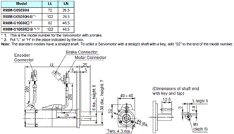
OMRON R88M-G, R7D-BP Dimensions
/Images/l_1956-25-136855-198x198.jpglast update: December 16, 2013
Compact!
Smaller Servo Drives for Multi-axis Applications
Reduce footprint in the control panel.
The super-compact SMARTSTEP is now even smaller.
The footprint has been reduced by 52%, helping to reduce control panel size.

Downsized Servo Drives for Compact PLCs
Reduce your duct pitch.
SMARTSTEP2 is only 120 mm in height. By mounting it onto the same duct as the compact CP1L PLC, the duct pitch can be reduced, minimizing control panel space.

Easy!
Easy Adjustment
Realtime autotuning sets the optimum gain.
An autotuning function calculates the device load in realtime and automatically sets the optimum gain, simplifying the adjustment procedure.

Easier Installation
Mount the Servo to a DIN Rail in one step.
The Servo Drive can be mounted onto a DIN Rail in a single step by using the DIN Rail Mounting Unit (sold separately) for easier assembly and easier maintenance replacements.

Easy Parameter Settings for Mass Production
Use the Parameter Unit as a copy tool.
Parameter can be easily set for many Servo Drives using the Parameter Unit, enabling easier assembly work in mass production lines.

Advanced Functionality!
Reduce Tact Time
Achieve high-speed positioning and movement.
The command pulse frequency at 500 kpps is twice as fast as previous OMRON models, enabling high-speed and high-precision control.

Check the Present Position
Monitor positioning errors with a feedback pulse.
The present position can be checked from the host using the feedback pulse sent from the Servo Drive to the Controller, allowing device errors to be monitored.

Change Pressing Force
Torque limiting function.
Set two torque limits, and switch between the two limits depending on the application, such as pressing or part insertions.

Reduce Mechanical Vibration
Quick suppression of vibration with an adaptive filter.
The vibration frequency is automatically measured to remove vibration. Even if the resonant frequency changes, realtime evaluation automatically follows the changes to reduce the effect of vibration due to low mechanical rigidity, such as for conveyer belts.

Reduce Tact Time
High-speed positioning with vibration control.
Mechanical vibration at the stop position caused by low mechanical rigidity can be suppressed by removing the vibration frequency.

last update: December 16, 2013
Purchase the OMRON Copyright Statement Please fill in the following
If you have just landed here, this product OMRON R88M-G, R7D-BP Motion / Drives,Motion / Drives is offered online by Tianin FLD Technical Co.,Ltd. This is an online store providing Motion / Drives at wholesale prices for consumers. You can call us or send enquiry, we would give you the prices, packing,deliverty and more detailed information on the R88M-G, R7D-BP We cooperate with DHL,TNT,FEDEX,UPS,EMS,etc.They guarantee to meet your needs in terms of time and money,even if you need your OMRON R88M-G, R7D-BPMotion / Drives tomorrow morning (aka overnight or next day air) on your desk, 2, 3 days or more.Note to international customers, YES, we ship worldwide.
G3PE (Three-phase) Solid State Contactors for Heaters/Features
E5AC-800 Digital Temperature Controller (Simple Type) (96 × 96 mm)/Features
DRT2-TS04[] Temperature Input Terminals/Features
SRT2-AD04 Analog Input Terminal/Features
K8DT-PH Phase-sequence Phase-loss Relay/Features
OMRON R88M-G, R7D-BP lineup
R88M-G, R7D-BP AC Servomotors and SMARTSTEP 2-series Servo Drives with Pulse String Inputs/Lineuplast update: October 2, 2017
Servo Drives
| Specifications | Model | |
|---|---|---|
| Single-phase 100 VAC | 50 W | R7D-BPA5L |
| 100 W | R7D-BP01L | |
| 200 W | R7D-BP02L | |
| Single-phase/three-phase 200 VAC | 50 W | R7D-BP01H |
| 100 W | ||
| 400 W | R7D-BP04H | |
| Single-phase 200 VAC | 200 W | R7D-BP02HH |
| Three-phase 200 VAC | 200 W | R7D-BP02H |
Servomotors
[INC] 3,000-r/min Cylindrical Servomotors
| Specifications | Model | |||
|---|---|---|---|---|
| Straight shaft | Straight shaft with key and tap | |||
| Without brake | 100 V | 50 W | R88M-G05030H | R88M-G05030H-S2 |
| 100 W | R88M-G10030L | R88M-G10030L-S2 | ||
| 200 W | R88M-G20030L | R88M-G20030L-S2 | ||
| 200 V | 50 W | R88M-G05030H | R88M-G05030H-S2 | |
| 100 W | R88M-G10030H | R88M-G10030H-S2 | ||
| 200 W | R88M-G20030H | R88M-G20030H-S2 | ||
| 400 W | R88M-G40030H | R88M-G40030H-S2 | ||
| With brake | 100 V | 50 W | R88M-G05030H-B | R88M-G05030H-BS2 |
| 100 W | R88M-G10030L-B | R88M-G10030L-BS2 | ||
| 200 W | R88M-G20030L-B | R88M-G20030L-BS2 | ||
| 200 V | 50 W | R88M-G05030H-B | R88M-G05030H-BS2 | |
| 100 W | R88M-G10030H-B | R88M-G10030H-BS2 | ||
| 200 W | R88M-G20030H-B | R88M-G20030H-BS2 | ||
| 400 W | R88M-G40030H-B | R88M-G40030H-BS2 | ||
Note: Models with oil seals are also available.
[INC] 3,000-r/min Flat Servomotors
| Specifications | Model | |||
|---|---|---|---|---|
| Straight shaft | Straight shaft with key and tap | |||
| Without brake | 100 V | 100W | R88M-GP10030L | R88M-GP10030L-S2 |
| 200W | R88M-GP20030L | R88M-GP20030L-S2 | ||
| 200 V | 100W | R88M-GP10030H | R88M-GP10030H-S2 | |
| 200W | R88M-GP20030H | R88M-GP20030H-S2 | ||
| 400W | R88M-GP40030H | R88M-GP40030H-S2 | ||
| With brake | 100 V | 100W | R88M-GP10030L-B | R88M-GP10030L-BS2 |
| 200W | R88M-GP20030L-B | R88M-GP20030L-BS2 | ||
| 200 V | 100W | R88M-GP10030H-B | R88M-GP10030H-BS2 | |
| 200W | R88M-GP20030H-B | R88M-GP20030H-BS2 | ||
| 400W | R88M-GP40030H-B | R88M-GP40030H-BS2 | ||
Note: Models with oil seals are also available.
Decelerators
Backlash: 3 Arcminutes Max.
Decelerators for Cylindrical Servomotors
| Specifications | Model | |
|---|---|---|
| Motor capacity | Gear ratio | |
| 50 W | 1/5 | R88G-HPG11A05100B |
| 1/9 | R88G-HPG11A09050B | |
| 1/21 | R88G-HPG14A21100B | |
| 1/33 | R88G-HPG14A33050B | |
| 1/45 | R88G-HPG14A45050B | |
| 100 W | 1/5 | R88G-HPG11A05100B |
| 1/11 | R88G-HPG14A11100B | |
| 1/21 | R88G-HPG14A21100B | |
| 1/33 | R88G-HPG20A33100B | |
| 1/45 | R88G-HPG20A45100B | |
| 200 W | 1/5 | R88G-HPG14A05200B |
| 1/11 | R88G-HPG14A11200B | |
| 1/21 | R88G-HPG20A21200B | |
| 1/33 | R88G-HPG20A33200B | |
| 1/45 | R88G-HPG20A45200B | |
| 400 W | 1/5 | R88G-HPG14A05400B |
| 1/11 | R88G-HPG20A11400B | |
| 1/21 | R88G-HPG20A21400B | |
| 1/33 | R88G-HPG32A33400B | |
| 1/45 | R88G-HPG32A45400B | |
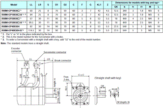
Note: 1. The standard models have a straight shaft.
Note: 2. To order a Servomotor with a straight shaft with key, add "J" to the end of the model number, in the place
indicated by the box.
Example: R88G-HPG11B05100BJ
Decelerator for Flat Servomotors
| Specifications | Model | |
|---|---|---|
| Motor capacity | Gear ratio | |
| 100 W | 1/5 | R88G-HPG11A05100PB |
| 1/11 | R88G-HPG14A11100PB | |
| 1/21 | R88G-HPG14A21100PB | |
| 1/33 | R88G-HPG20A33100PB | |
| 1/45 | R88G-HPG20A45100PB | |
| 200 W | 1/5 | R88G-HPG14A05200PB |
| 1/11 | R88G-HPG20A11200PB | |
| 1/21 | R88G-HPG20A21200PB | |
| 1/33 | R88G-HPG20A33200PB | |
| 1/45 | R88G-HPG20A45200PB | |
| 400 W | 1/5 | R88G-HPG20A05400PB |
| 1/11 | R88G-HPG20A11400PB | |
| 1/21 | R88G-HPG20A21400PB | |
| 1/33 | R88G-HPG32A33400PB | |
| 1/45 | R88G-HPG32A45400PB | |
Note: 1. The standard models have a straight shaft.
Note: 2. To order a Servomotor with a straight shaft with key, add "J" to the end of the model number, in the place
indicated by the box.
Example: R88G-HPG11B05100BJ
Backlash: 15 Arcminutes Max.
Decelerators for Cylindrical Servomotors
| Specifications | Model | |
|---|---|---|
| Motor capacity | Gear ratio | |
| 50 W | 1/5 | R88G-VRXF05B100CJ |
| 1/9 | R88G-VRXF09B100CJ | |
| 1/15 | R88G-VRXF15B100CJ | |
| 1/25 | R88G-VRXF25B100CJ | |
| 100 W | 1/5 | R88G-VRXF05B100CJ |
| 1/9 | R88G-VRXF09B100CJ | |
| 1/15 | R88G-VRXF15B100CJ | |
| 1/25 | R88G-VRXF25B100CJ | |
| 200 W | 1/5 | R88G-VRXF05B200CJ |
| 1/9 | R88G-VRXF09C200CJ | |
| 1/15 | R88G-VRXF15C200CJ | |
| 1/25 | R88G-VRXF25C200CJ | |
| 400 W | 1/5 | R88G-VRXF05C400CJ |
| 1/9 | R88G-VRXF09C400CJ | |
| 1/15 | R88G-VRXF15C400CJ | |
| 1/25 | R88G-VRXF25C400CJ | |
Note: 1. The standard models have a straight shaft with a key.
Note: 2. The backlash is the value when a load of ±4% of the allowable output torque is applied to the output shaft.
Decelerators for Flat Servomotors
| Specifications | Model | |
|---|---|---|
| Motor capacity | Gear ratio | |
| 100 W | 1/5 | R88G-VRXF05B100PCJ |
| 1/9 | R88G-VRXF09B100PCJ | |
| 1/15 | R88G-VRXF15B100PCJ | |
| 1/25 | R88G-VRXF25B100PCJ | |
| 200 W | 1/5 | R88G-VRXF05B200PCJ |
| 1/9 | R88G-VRXF09C200PCJ | |
| 1/15 | R88G-VRXF15C200PCJ | |
| 1/25 | R88G-VRXF25C200PCJ | |
| 400 W | 1/5 | R88G-VRXF05C400PCJ |
| 1/9 | R88G-VRXF09C400PCJ | |
| 1/15 | R88G-VRXF15C400PCJ | |
| 1/25 | R88G-VRXF25C400PCJ | |
Note: 1. The standard models have a straight shaft with a key.
Note: 2. The backlash is the value when a load of ±4% of the allowable output torque is applied to the output shaft.
Note: Decelerators (Backlash = 15' Max.)
The new R88G-VRXF Series of the Decelerators (Backlash = 15' Max.) was released in October 2017.
The old R88G-VRSF Series will be discontinued at the end of March 2019.
Accessories and Cables
Control Cables (for CN1)
| Specifications | Model | |
|---|---|---|
| Connector-Terminal Block Cables | 1 m | XW2Z-100J-B28 |
| 2 m | XW2Z-200J-B28 | |
| General-purpose Control Cables | 1 m | R7A-CPB001S |
| 2 m | R7A-CPB002S | |
Encoder Cables (for CN2) (Standard Cables)
| Specifications | Model | |
|---|---|---|
| Standard Cables (connectors attached) | 3 m | R88A-CRGB003C |
| 5 m | R88A-CRGB005C | |
| 10 m | R88A-CRGB010C | |
| 15 m | R88A-CRGB015C | |
| 20 m | R88A-CRGB020C | |
Servomotor Power Cables (for CNB) (Standard Cables)
| Specifications | Model | |
|---|---|---|
| Standard Cables (connectors attached) | 3 m | R7A-CAB003S |
| 5 m | R7A-CAB005S | |
| 10 m | R7A-CAB010S | |
| 15 m | R7A-CAB015S | |
| 20 m | R7A-CAB020S | |
Brake Cables (Standard Cables)
| Specifications | Model | |
|---|---|---|
| Standard Cables | 3 m | R88A-CAGA003B |
| 5 m | R88A-CAGA005B | |
| 10 m | R88A-CAGA010B | |
| 15 m | R88A-CAGA015B | |
| 20 m | R88A-CAGA020B | |
Encoder Cables (for CN2) (Robot Cables)
| Specifications | Model | |
|---|---|---|
| Robot Cables (connectors attached) | 3 m | R88A-CRGB003CR |
| 5 m | R88A-CRGB005CR | |
| 10 m | R88A-CRGB010CR | |
| 15 m | R88A-CRGB015CR | |
| 20 m | R88A-CRGB020CR | |
Servomotor Power Cables (for CNB) (Robot Cables)
| Specifications | Model | |
|---|---|---|
| Robot Cables (connectors attached) | 3 m | R7A-CAB003SR |
| 5 m | R7A-CAB005SR | |
| 10 m | R7A-CAB010SR | |
| 15 m | R7A-CAB015SR | |
| 20 m | R7A-CAB020SR | |
Brake Cables (Robot Cables)
| Specifications | Model | |
|---|---|---|
| Robot Cables | 3 m | R88A-CAGA003BR |
| 5 m | R88A-CAGA005BR | |
| 10 m | R88A-CAGA010BR | |
| 15 m | R88A-CAGA015BR | |
| 20 m | R88A-CAGA020BR | |
Personal Computer Monitor Cable
| Specifications | Model | |
|---|---|---|
| Personal Computer Monitor Cable | 2 m | R88A-CCG002P2 |
Power Supply Cables
| Specifications | Model | |
|---|---|---|
| Power Supply Input Cable for Single-Phase Power (connectors attached) | 2 m | R7A-CLB002S2 |
| Power Supply Input Cable for Three-Phase Power (connectors attached) | 2 m | R7A-CLB002S3 |
| External Regenerative Resistor Connection Cable | 2 m | R7A-CLB002RG |
Connectors
| Specifications | Model |
|---|---|
| Main Circuit Connector (CNA) | R7A-CNB01P |
| Servomotor Connector (CNB) | R7A-CNB01A |
| Control Input Connector (CN1) | R88A-CNW01C |
| Encoder Input Connector (CN2) | R88A-CNW01R |
| Servomotor Connector for Encoder Cable | R88A-CNG02R |
| Servomotor Connector for Servomotor Power Cable | R88A-CNG01A |
| Brake Cable Connector | R88A-CNG01B |
Connector-Terminal Block Conversion Units
| Specifications | Model |
|---|---|
| With M3 screws | XW2B-34G4 |
| With M3.5 screws | XW2B-34G5 |
| With M3 screws | XW2D-34G6 |
External Regeneration Resistors
| Specifications | Model |
|---|---|
| 220 W, 47 Ω | R88A-RR22047S1 |
| 80 W, 100 Ω | R88A-RR080100S |
| 80 W, 50 Ω | R88A-RR08050S |
Reactors
| Specifications | Applicable Servo Drive | Model |
|---|---|---|
| Single-phase 100 V | R7D-BPA5L | 3G3AX-DL2002 |
| R7D-BP01L | 3G3AX-DL2004 | |
| R7D-BP02L | 3G3AX-DL2007 | |
| Single-phase 200 V | R7D-BP01H | 3G3AX-DL2004 |
| R7D-BP02HH | 3G3AX-DL2004 | |
| R7D-BP04H | 3G3AX-DL2007 | |
| Three-phase 200 V | R7D-BP01H | 3G3AX-AL2025 |
| R7D-BP02H | 3G3AX-AL2025 | |
| R7D-BP04H | 3G3AX-AL2025 |
DIN Rail Mounting Unit
| Specifications | Model |
|---|---|
| DIN Rail Mounting Unit | R7A-DIN01B |
Parameter Unit
| Specifications | Model |
|---|---|
| Parameter Unit | R88A-PR02G |
Direct Connection Cable
| Specification (Unit) | The number of axes | Length | Model |
|---|---|---|---|
| CJ1W-NC234/-NC434 (Line-driver output type) | for 1 axis | 1 m | XW2Z-100J-G12 |
| 5 m | XW2Z-500J-G12 | ||
| 10 m | XW2Z-10MJ-G12 | ||
| for 2 axis | 1 m | XW2Z-100J-G4 | |
| 5 m | XW2Z-500J-G4 | ||
| 10 m | XW2Z-10MJ-G4 | ||
| CJ1W-NC214/-NC414 (Open collector output type) | for 1 axis | 1 m | XW2Z-100J-G16 |
| 3 m | XW2Z-300J-G16 | ||
| for 2 axis | 1 m | XW2Z-100J-G8 | |
| 3 m | XW2Z-300J-G8 |
Servo Relay Units (for CN1)
| Specifications | Model | |
|---|---|---|
| For CJ1W-NC133/-NC113 For CS1W-NC133/-NC113 For C200HW-NC113 * | XW2B-20J6-1B | |
| For CJ1W-NC233/-NC433/-NC213/-NC413 For CS1W-NC233/-NC433/-NC213/-NC413 For C200HW-NC213/-NC413 * | XW2B-40J6-2B | |
| For CJ1M-CPU21 For CJ1M-CPU22 For CJ1M-CPU23 | for 1 axis | XW2B-20J6-8A |
| for 2 axis | XW2B-40J6-9A | |
| For FQM1-MMP22 | XW2B-80J7-12A | |
* C200HW-NC was discontinued.
Servo Relay Unit Cables (for Servo Drives)
| Specifications | Model | |
|---|---|---|
| For CJ1M (XW2B-20J6-8A/XW2B-40J6-9A) | 1 m | XW2Z-100J-B32 |
| 2 m | XW2Z-200J-B32 | |
| For FQM1-MMP22 (XW2B-80J7-12A) | 1 m | XW2Z-100J-B30 |
| 2 m | XW2Z-200J-B30 | |
Servo Relay Unit Cables (for Position Control Units)
| Specifications | Model | ||
|---|---|---|---|
| For CJ1W-NC133 | 0.5 m | XW2Z-050J-A18 | |
| 1 m | XW2Z-100J-A18 | ||
| For CJ1W-NC233/-NC433 | 0.5 m | XW2Z-050J-A19 | |
| 1 m | XW2Z-100J-A19 | ||
| For CS1W-NC133 | 0.5 m | XW2Z-050J-A10 | |
| 1 m | XW2Z-100J-A10 | ||
| For CS1W-NC233/-NC433 | 0.5 m | XW2Z-050J-A11 | |
| 1 m | XW2Z-100J-A11 | ||
| For CJ1W-NC113 | 0.5 m | XW2Z-050J-A14 | |
| 1 m | XW2Z-100J-A14 | ||
| For CJ1W-NC213/-NC413 | 0.5 m | XW2Z-050J-A15 | |
| 1 m | XW2Z-100J-A15 | ||
| For CS1W-NC113 For C200HW-NC113 * | 0.5 m | XW2Z-050J-A6 | |
| 1 m | XW2Z-100J-A6 | ||
| For CS1W-NC213/-NC413 For C200HW-NC213/-NC413 * | 0.5 m | XW2Z-050J-A7 | |
| 1 m | XW2Z-100J-A7 | ||
| For CJ1M-CPU21 For CJ1M-CPU22 For CJ1M-CPU23 | 0.5 m | XW2Z-050J-A33 | |
| 1 m | XW2Z-100J-A33 | ||
| For FQM1-MMP22 | General-purpose I/O Cables | 0.5 m | XW2Z-050J-A28 |
| 1 m | XW2Z-100J-A28 | ||
| 2 m | XW2Z-200J-A28 | ||
| Special I/O Cables | 0.5 m | XW2Z-050J-A30 | |
| 1 m | XW2Z-100J-A30 | ||
| 2 m | XW2Z-200J-A30 | ||
* C200HW-NC was discontinued.
FA Integrated Tool Package CX-One
| Product name | Specifications | Model | Stand- ards | ||
|---|---|---|---|---|---|
| Number of licenses | Media | ||||
| FA Integrated Tool Package CX-One Version 4.[] | The CX-One is a comprehensive software package that integrates Support Software for OMRON PLCs and components. CX-One runs on following OS. OS: Windows XP (Service Pack 3 or higher, 32- bit version)/Windows Vista (32-bit/64-bit version)/ Windows 7 (32-bit/64-bit version)/Windows 8 (32- bit/64-bit version)/Windows 8.1 (32-bit/64-bit version)/Windows 10 (32-bit/64-bit version) CX-One Version.4.[] includes CX-Drive Ver.2.[]. | 1 license * | DVD | CXONE-AL01D-V4 | --- |
* Multi licenses (3, 10, 30, or 50 licenses) and DVD media without licenses are also available for the CX-One.
last update: October 2, 2017
OMRON R88M-G, R7D-BP catalog
R88M-G, R7D-BP AC Servomotors and SMARTSTEP 2-series Servo Drives with Pulse String Inputs/Catalog- Catalog
- Manual
- CAD
English
Global Edition
| Catalog Name | Catalog Number [size] | Last Update | |
|---|---|---|---|
| | I813-E1-04 [7883KB] | Dec 25, 201820181225 | SMARTSTEP2 Catalog |
OMRON R88M-G, R7D-BP specification
R88M-G, R7D-BP AC Servomotors and SMARTSTEP 2-series Servo Drives with Pulse String Inputs/Specificationslast update: December 25, 2018
Servo Drive Specifications (R7D-BP)
General Specifications
| Item | Specifications | ||
|---|---|---|---|
| Ambient operating temperature Ambient operating humidity | 0 to 55 °C, 90% max. (with no condensation) | ||
| Ambient storage temperature Ambient storage humidity | -20 to 65 °C, 90% max. (with no condensation) | ||
| Storage and operating atmosphere | No corrosive gasses, no dust, no iron dust, no exposure to moisture or cutting oil | ||
| Vibration resistance | 10 to 60 Hz; acceleration: 5.9 m/s2 (0.6 G) max. | ||
| Impact resistance | Acceleration of 19.6 m/s2 max. 3 times each in X, Y, and Z directions. | ||
| Insulation resistance | Between power supply/power line terminals and frame ground: 0.5 MΩ. min. (at 500 VDC) | ||
| Dielectric strength | Between power supply/power line terminals and frame ground: 1,500 VAC for 1 min at 50/60 Hz Between each control signal and frame ground: 500 VAC for 1 min | ||
| Altitude | 1,000 m above sea level max. (860 hp min.) | ||
| Degree of protection | Built into panel (IP10). | ||
| International standards | EC Directives | EMC Directive | EN 55011 class A group 1 EN 61000-6-2 |
| Low Voltage Directive | EN 50178 | ||
| UL standards | UL 508C | ||
| cUL standards | cUL C22.2 No.14 | ||
| Korean Radio Regulations (KC) | Certified | ||
Note: 1. The above items reflect individual evaluation testing. The results may differ under compound conditions.
Note: 2. Always disconnect all connections to the Servo Drive before you perform insulation resistance tests on it. If you
perform an insulation resistance test while the Servo Drive is connected, the Servo Drive may be damaged.
Never perform dielectric strength tests on the Servo Drive. Failure to follow this precaution may result in
damaging internal elements.
Note: 3. Depending on the operating conditions, some Servo Drive parts will require maintenance.
Note: 4. The service life of the Servo Drive is 50,000 hours at an average ambient temperature of 40°C at 80% of the
rated torque (excluding axial-flow fan).
Characteristics
100 VAC specification
| Item | Servo Drive model | ||
|---|---|---|---|
| R7D-BPA5L | R7D-BP01L | R7D-BP02L | |
| Continuous output current (rms) | 1.0 A | 1.6 A | 2.5 A |
| Momentary maximum output current (rms) | 3.3 A | 5.1 A | 7.5 A |
| Power supply capacity | 0.16 KVA | 0.25 KVA | 0.42 KVA |
| Input power supply voltage (main circuit) | Single-phase 100 to 115 VAC (85 to 127 V), 50/60 Hz | ||
| Input power supply current (rms) (main circuit) | 1.4 A | 2.2 A | 3.7 A |
| Heat generated (main circuit) | 12 W | 16 W | 22 W |
| Control method | All-digital servo | ||
| Inverter method | IGBT-driven PWM method | ||
| PWM frequency | 12 kHz | 6 kHz | |
| Maximum response frequency (command pulses) | Line drive: 500 kpps, Open collector: 200 kpps | ||
| Weight | 0.35 kg | 0.42 kg | |
| Applicable motor capacity | 50 W | 100 W | 200 W |
200 VAC specification
| Item | Servo Drive model | |||
|---|---|---|---|---|
| R7D-BP01H | R7D-BP02HH | R7D-BP02H | R7D-BP04H | |
| Continuous output current (rms) | 1.0 A | 1.6 A | 1.6 A | 2.5 A |
| Momentary maximum output current (rms) | 3.3 A | 4.9 A | 4.9 A | 7.8 A |
| Power supply capacity | 0.27 KVA (0.30 KVA) * | 0.35 KVA | 0.42 KVA | 0.69 KVA (0.77 KVA) * |
| Input power supply voltage (main circuit) | Both single-phase and three-phase 200 to 240 VAC (170 to 264 V), 50/60 Hz | |||
| Input power supply current (rms) (main circuit) | 0.7 A (1.5 A) * | 1.6 A | 1.1 A | 1.8 A (3.5 A) * |
| Heat generated (main circuit) | 14 W | 16 W | 20 W | 26W |
| Control method | All-digital servo | |||
| Inverter method | IGBT-driven PWM method | |||
| PWM frequency | 12 kHz | 6 kHz | ||
| Maximum response frequency (command pulses) | Line drive: 500 kpps, Open collector: 200 kpps | |||
| Weight | 0.35 kg | 0.42 kg | 0.35 kg | 0.42 kg |
| Applicable motor capacity | 100 W | 200 W | 200 W | 400 W |
* Values inside parentheses ( ) are for single-phase 200-V use.
Servomotor Specifications (R88M-G)
General Specifications
| Item | Specifications | ||
|---|---|---|---|
| Ambient operating temperature Ambient operating humidity | 0 to 40 °C, 85% max. (with no condensation) | ||
| Ambient storage temperature Ambient storage humidity | - 20 to 65 °C, 85% max. (with no condensation) | ||
| Storage and operating atmosphere | No corrosive gases | ||
| Vibration resistance | 49 m/s2 max. in the X, Y, and Z directions | ||
| Impact resistance | Acceleration of 98 m/s2 max. 3 times each in the X, Y, and Z directions | ||
| Insulation resistance | 20 MΩ min. at 500 VDC between the power terminals and FG terminal | ||
| Dielectric strength | 1,500 VAC (50 or 60 Hz) for 1 minute between the power terminals and FG terminal | ||
| Operating position | Any direction | ||
| Insulation class | Type B | ||
| Construction | Totally-enclosed, self-cooling | ||
| Degree of protection | IP65 (excluding the through-shaft portion) | ||
| Vibration class | V-15 | ||
| Mounting method | Flange-mounting | ||
| International standards | EC Directives | Low Voltage Directive | IEC 60034-5:2001 |
| UL standards | UL 1004 File No. E179189 | ||
| cUL standards | cUL 22.2, No.100 | ||
Note: Always disconnect all connections to the Servo Drive before you perform insulation resistance tests on it. If you
perform an insulation resistance test while the Servo Drive is connected, the Servo Drive may be damaged.
Never perform dielectric strength tests on the Servo Drive. Failure to follow this precaution may result in damaging
internal elements.
Characteristics
3,000-r/min Cylindrical Servomotors
100 VAC specification
| Item | Unit | R88M-G05030H | R88M-G10030L | R88M-G20030L | |
|---|---|---|---|---|---|
| Rated output *1 | W | 50 | 100 | 200 | |
| Rated torque *1 | Nm | 0.16 | 0.32 | 0.64 | |
| Rated rotation speed | r/min | 3000 | |||
| Max. rotation speed | r/min | 5000 | |||
| Max. momentary torque *1 | Nm | 0.48 | 0.95 | 1.78 | |
| Rated current *1 | A (rms) | 1.1 | 1.7 | 2.5 | |
| Max. momentary current *1 | A (rms) | 3.4 | 5.1 | 7.6 | |
| Rotor inertia | kg·m2 | 2.5 × 10⁻⁶ | 5.1 × 10⁻⁶ | 1.4 × 10⁻⁵ | |
| Applicable load inertia | --- | 30 times rotor inertia max. | |||
| Power rate *1 | kW/s | 10.4 | 20.1 | 30.3 | |
| Allowable radial load *2 | N | 68 | 68 | 245 | |
| Allowable thrust load *2 | N | 58 | 58 | 98 | |
| Weight | Without brake | kg | 0.3 | 0.5 | 0.8 |
| With brake | kg | 0.5 | 0.7 | 1.3 | |
| Radiation shield dimensions (material) | --- | 100 × 80 × t10 (Al) | 130 × 120 × t12 (Al) | ||
| Brake specifications | Brake inertia | kg·m2 | 2.0 × 10⁻⁷ | 2.0 × 10⁻⁷ | 1.8 × 10⁻⁶ |
| Excitation voltage *3 | V | 24 VDC ± 10% | |||
| Power consumption (at 20 °C) | W | 7 | 7 | 9 | |
| Current consumption (at 20 °C) | A | 0.3 | 0.3 | 0.36 | |
| Static friction torque | Nm | 0.29 min. | 0.29 min. | 1.27 min. | |
| Attraction time *4 | ms | 35 max. | 35 max. | 50 max. | |
| Release time *4 | ms | 20 max. | 20 max. | 15 max. | |
| Backlash | ± 1 ° | ||||
| Allowable work per braking operation | J | 39.2 | 39.2 | 137 | |
| Allowable total work | J | 4.9 × 10³ | 4.9 × 10³ | 44.1 × 10³ | |
| Allowable angular acceleration | rad/s2 | 30,000 max. (Speed of 2,800 r/min minimum must not be stopped in less than 10 ms) | |||
| Brake life | --- | 10,000,000 operations min. | |||
| Rating | --- | Continuous | |||
| Insulation class | --- | Type F | |||
*1. These are the values when the Servomotor is combined with a Servo Drive at room temperature.
The momentary maximum torque shown above indicates the standard value.
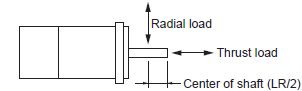
*2. The allowable radial and thrust loads are the values determined for a service life of 20,000 hours at normal
operating temperatures. The values are also for the locations shown in the following diagram.
*3. The brakes operate when the circuit is open (i.e., they are released when voltage is applied).
*4. The operation time is the measured value (reference value) with a varistor installed as a surge suppressor.
200 VAC specification
| Item | Unit | R88M- G05030H | R88M- G10030H | R88M- G20030H | R88M- G40030H | |
|---|---|---|---|---|---|---|
| Rated output *1 | W | 50 | 100 | 200 | 400 | |
| Rated torque *1 | Nm | 0.16 | 0.32 | 0.64 | 1.3 | |
| Rated rotation speed | r/min | 3000 | ||||
| Max. rotation speed | r/min | 5000 | ||||
| Max. momentary torque *1 | N·Em | 0.48 | 0.95 | 1.78 | 3.60 | |
| Rated current *1 | A (rms) | 1.1 | 1.1 | 1.6 | 2.6 | |
| Max. momentary current *1 | A (rms) | 3.4 | 3.4 | 4.9 | 7.9 | |
| Rotor inertia | kg·m 2 | 2.5 × 10⁻⁶ | 5.1 × 10⁻⁶ | 1.4 × 10⁻⁵ | 2.6 × 10⁻⁵ | |
| Applicable load inertia | --- | 30 times rotor inertia max. | ||||
| Power rate *1 | kW/s | 10.4 | 20.1 | 30.3 | 62.5 | |
| Allowable radial load *2 | N | 68 | 68 | 245 | 245 | |
| Allowable thrust load *2 | N | 58 | 58 | 98 | 98 | |
| Weight | Without brake | kg | 0.3 | 0.5 | 0.8 | 1.2 |
| With brake | kg | 0.5 | 0.7 | 1.3 | 1.7 | |
| Radiation shield dimensions (material) | --- | 100 × 80 × t10 (Al) | 130 × 120 × t12 (Al) | |||
| Brake specifi- cations | Brake inertia | kg·m 2 | 2.0 × 10⁻⁷ | 2.0 × 10⁻⁷ | 1.8 × 10⁻⁶ | 7.5 × 10⁻⁶ |
| Excitation voltage *3 | V | 24 VDC ± 10% | ||||
| Power consumption (at 20 °C) | W | 7 | 7 | 9 | 9 | |
| Current consumption (at 20 °C) | A | 0.30 | 0.30 | 0.36 | 0.36 | |
| Static friction torque | Nm | 0.29 min. | 0.29 min. | 1.27 min. | 1.27 min. | |
| Attraction time *4 | ms | 35 max. | 35 max. | 50 max. | 50 max. | |
| Release time *4 | ms | 20 max. | 20 max. | 15 max. | 15 max. | |
| Backlash | ± 1 ° | |||||
| Allowable work per braking operation | J | 39.2 | 39.2 | 137 | 196 | |
| Allowable total work | J | 4.9 × 10³ | 4.9 × 10³ | 44.1 × 10³ | 147 × 103 | |
| Allowable angular acceleration | rad/s2 | 30,000 max. (Speed of 2,800 r/min minimum must not be stopped in less than 10 ms) | ||||
| Brake life | --- | 10,000,000 operations min. | ||||
| Rating | --- | Continuous | ||||
| Insulation class | --- | Type F | ||||
*1. These are the values when the Servomotor is combined with a Servo Drive at room temperature.
The momentary maximum torque shown above indicates the standard value.
*2. The allowable radial and thrust loads are the values determined for a service life of 20,000 hours at normal
operating temperatures. The values are also for the locations shown in the following diagram.
*3. The brakes operate when the circuit is open (i.e., they are released when voltage is applied).
*4. The operation time is the measured value (reference value) with a varistor installed as a surge suppressor.
3,000-r/min Flat Servomotors
100 VAC specification
| Item | Unit | R88M-GP10030L | R88M-GP20030L | |
|---|---|---|---|---|
| Rated output *1 | W | 100 | 200 | |
| Rated torque *1 | Nm | 0.32 | 0.64 | |
| Rated rotation speed | r/min | 3000 | ||
| Max. rotation speed | r/min | 5000 | ||
| Max. momentary torque *1 | Nm | 0.85 | 1.86 | |
| Rated current *1 | A(rms) | 1.6 | 2.5 | |
| Max. momentary current *1 | A(0-p) | 6.9 | 10.5 | |
| Rotor inertia | kg·m 2 | 9.0 × 10⁻⁶ | 3.4 × 10⁻⁵ | |
| Applicable load inertia | --- | 20 times rotor inertia max. | ||
| Power rate *1 | kW/s | 11.4 | 12.0 | |
| Allowable radial load *2 | N | 68 | 245 | |
| Allowable thrust load *2 | N | 58 | 98 | |
| Weight | Without brake | kg | 0.65 | 1.3 |
| With brake | kg | 0.90 | 2.0 | |
| Radiation shield dimensions (material) | --- | 130 × 120 × t10 (Al) | 170 × 160 × t12 (Al) | |
| Brake specifica- tions | Brake inertia | kg·m 2 | 3.0 × 10⁻⁶ | 9.0 × 10⁻⁶ |
| Excitation voltage *3 | V | 24 VDC ± 10% | ||
| Power consumption (at 20 °C) | W | 7 | 10 | |
| Current consumption (at 20 °C) | A | 0.29 | 0.41 | |
| Static friction torque | Nm | 0.29 min. | 1.27 min. | |
| Attraction time *4 | ms | 50 max. | 60 max. | |
| Release time *4 | ms | 15 max. | 15 max. | |
| Backlash | ± 1 ° | |||
| Allowable work per braking operation | J | 137 | 196 | |
| Allowable total work | J | 44.1 × 10³ | 147 × 103 | |
| Allowable angular acceleration | rad/s2 | 10,000 max. (Speed of 950 r/min minimum must not be stopped in less than 10 ms) | ||
| Brake life | --- | 10,000,000 operations min. | ||
| Rating | --- | Continuous | ||
| Insulation class | --- | Type F | ||
*1. These are the values when the Servomotor is combined with a Servo Drive at room temperature.
The momentary maximum torque shown above indicates the standard value.
*2. The allowable radial and thrust loads are the values determined for a service life of 20,000 hours at normal
operating temperatures. The values are also for the locations shown in the following diagram.
*3. The brakes operate when the circuit is open (i.e., they are released when voltage is applied).
*4. The operation time is the measured value (reference value) with a varistor installed as a surge suppressor.
200 VAC specification
| Item | Unit | R88M-GP10030H | R88M-GP20030H | R88M-GP40030H | |
|---|---|---|---|---|---|
| Rated output *1 | W | 100 | 200 | 400 | |
| Rated torque *1 | Nm | 0.32 | 0.64 | 1.3 | |
| Rated rotation speed | r/min | 3000 | |||
| Max. rotation speed | r/min | 5000 | |||
| Max. momentary torque *1 | Nm | 0.90 | 1.82 | 3.60 | |
| Rated current *1 | A(rms) | 1.0 | 1.6 | 4.4 | |
| Max. momentary current *1 | A(0-p) | 4.3 | 6.8 | 18.6 | |
| Rotor inertia | kg·m 2 | 9.0 × 10⁻⁶ | 3.4 × 10⁻⁵ | 6.4 × 10⁻⁵ | |
| Applicable load inertia | --- | 20 times rotor inertia max. | |||
| Power rate *1 | kW/s | 11.4 | 11.8 | 25.5 | |
| Allowable radial load *2 | N | 68 | 245 | 245 | |
| Allowable thrust load *2 | N | 58 | 98 | 98 | |
| Weight | Without brake | kg | 0.7 | 1.3 | 1.8 |
| With brake | kg | 0.9 | 2.0 | 2.5 | |
| Radiation shield dimensions (material) | --- | 130 × 120 × t10 (Al) | 170 × 160 × t12 (Al) | ||
| Brake specifica- tions | Brake inertia | kg·m 2 | 3.0 × 10⁻⁶ | 9.0 × 10⁻⁶ | 9.0 × 10⁻⁶ |
| Excitation voltage *3 | V | 24 VDC ± 10% | |||
| Power consumption (at 20 °C) | W | 7 | 10 | 10 | |
| Current consumption (at 20 °C) | A | 0.29 | 0.41 | 0.41 | |
| Static friction torque | Nm | 0.29 min. | 1.27 min. | 1.27 min. | |
| Attraction time *4 | ms | 50 max. | 60 max. | 60 max. | |
| Release time*4 | ms | 15 max. | 15 max. | 15 max. | |
| Backlash | ± 1 ° | ||||
| Allowable work per braking operation | J | 137 | 196 | 196 | |
| Allowable total work | J | 44.1 × 10³ | 147 × 103 | 147 × 103 | |
| Allowable angular acceleration | rad/s2 | 10,000 max. (Speed of 950 r/min minimum must not be stopped in less than 10 ms) | |||
| Brake life | --- | 10,000,000 operations min. | |||
| Rating | --- | Continuous | |||
| Insulation class | --- | Type F | |||
*1. These are the values when the Servomotor is combined with a Servo Drive at room temperature.
The momentary maximum torque shown above indicates the standard value.
*2. The allowable radial and thrust loads are the values determined for a service life of 20,000 hours at normal
operating temperatures. The values are also for the locations shown in the following diagram.
*3. The brakes operate when the circuit is open (i.e., they are released when voltage is applied).
*4. The operation time is the measured value (reference value) with a varistor installed as a surge suppressor.
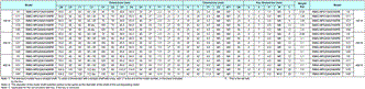
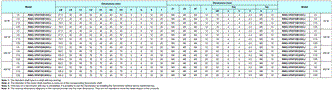
Decelerator Specifications (R88G-HPG/VRXF)
Standard Models and Specifications
Backlash: 3 Arcminutes Max.
Decelerators for Cylindrical Servomotors
| Model (R88G-) | Rated speed | Rated torque | Ra- tio | Maxi- mum mo- men- tary speed | Maxi- mum mo- men- tary torque | Decel- erator inertia | Al- lowable radial load | Al- lowable thrust load | Weight | ||
|---|---|---|---|---|---|---|---|---|---|---|---|
| r/min | Nm | % | r/min | Nm | kg·m2 | N | N | kg | |||
| 50 W | 1/5 | HPG11A05100B | 600 | 0.60 | 75 | 1000 | 1.80 | 5.00× 10⁻⁷ | 135 | 538 | 0.29 |
| 1/9 | HPG11A09050B | 333 | 1.17 | 81 | 555 | 3.51 | 3.00× 10⁻⁷ | 161 | 642 | 0.29 | |
| 1/21 | HPG14A21100B | 143 | 2.18 | 65 | 238 | 6.54 | 5.00× 10⁻⁶ | 340 | 1358 | 1.04 | |
| 1/33 | HPG14A33050B | 91 | 3.73 | 71 | 151 | 11.2 | 4.40× 10⁻⁶ | 389 | 1555 | 1.04 | |
| 1/45 | HPG14A45050B | 67 | 5.09 | 71 | 111 | 15.2 | 4.40× 10⁻⁶ | 427 | 1707 | 1.04 | |
| 100 W | 1/5 | HPG11A05100B | 600 | 1.37 | 86 | 1000 | 4.07 | 5.00× 10⁻⁷ | 135 | 538 | 0.29 |
| 1/11 | HPG14A11100B | 273 | 2.63 | 75 | 454 | 7.80 | 6.00× 10⁻⁶ | 280 | 1119 | 1.04 | |
| 1/21 | HPG14A21100B | 143 | 5.40 | 80 | 238 | 16.0 | 5.00× 10⁻⁶ | 340 | 1358 | 1.04 | |
| 1/33 | HPG20A33100B | 91 | 6.91 | 65 | 151 | 20.5 | 6.50× 10⁻⁵ | 916 | 3226 | 2.4 | |
| 1/45 | HPG20A45100B | 67 | 9.42 | 65 | 111 | 27.9 | 6.50× 10⁻⁵ | 1006 | 3541 | 2.4 | |
| 200 W | 1/5 | HPG14A05200B | 600 | 2.49 | 78 | 1000 | 7.44 | 2.07× 10⁻⁵ | 221 | 883 | 1.02 |
| 1/11 | HPG14A11200B | 273 | 6.01 | 85 | 454 | 17.9 | 1.93× 10⁻⁵ | 280 | 1119 | 1.09 | |
| 1/21 | HPG20A21200B | 143 | 10.2 | 76 | 238 | 30.6 | 4.90× 10⁻⁵ | 800 | 2817 | 2.9 | |
| 1/33 | HPG20A33200B | 91 | 17.0 | 81 | 151 | 50.8 | 4.50× 10⁻⁵ | 916 | 3226 | 2.9 | |
| 1/45 | HPG20A45200B | 67 | 23.2 | 81 | 111 | 69.3 | 4.50× 10⁻⁵ | 1006 | 3541 | 2.9 | |
| 400 W | 1/5 | HPG14A05400B | 600 | 5.66 | 87 | 1000 | 16.5 | 2.07× 10⁻⁵ | 221 | 883 | 1.09 |
| 1/11 | HPG20A11400B | 273 | 11.7 | 82 | 454 | 34.2 | 5.70× 10⁻⁵ | 659 | 2320 | 2.9 | |
| 1/21 | HPG20A21400B | 143 | 23.5 | 86 | 238 | 68.8 | 4.90× 10⁻⁵ | 800 | 2547 | 2.9 | |
| 1/33 | HPG32A33400B | 91 | 34.7 | 81 | 151 | 101.7 | 6.20× 10⁻⁵ | 1565 | 6240 | 7.5 | |
| 1/45 | HPG32A45400B | 67 | 47.4 | 81 | 111 | 138.6 | 6.10× 10⁻⁵ | 1718 | 6848 | 7.5 | |
Note: 1. The Decelerator inertia is the Servomotor shaft conversion value.
Note: 2. The enclosure rating for Servomotors with Decelerators is IP44.
Note: 3. The allowable radial load is the value at the LR/2 position.
Note: 4. The standard models have a straight shaft. To order a Servomotor with a straight shaft with a key, add a "J" to
the end of the model number, in the place indicated by the box.
Decelerator for Flat Servomotors
| Model (R88G-) | Rated speed | Rated torque | Ra- tio | Maxi- mum mo- men- tary speed | Maxi- mum mo- men- tary torque | Decel- erator inertia | Al- lowable radial load | Al- lowable thrust load | Weight | ||
|---|---|---|---|---|---|---|---|---|---|---|---|
| r/min | Nm | % | r/min | Nm | kg·m2 | N | N | kg | |||
| 100 W | 1/5 | HPG11A05100PB | 600 | 1.37 | 85 | 1000 | 3.84 (3.63) | 5.00× 10⁻⁷ | 135 | 538 | 0.34 |
| 1/11 | HPG14A11100PB | 273 | 2.63 | 75 | 454 | 7.39 (6.98) | 6.00× 10⁻⁶ | 280 | 1119 | 1.04 | |
| 1/21 | HPG14A21100PB | 143 | 5.40 | 80 | 238 | 15.2 (14.6) | 5.00× 10⁻⁶ | 340 | 1358 | 1.04 | |
| 1/33 | HPG20A33100PB | 91 | 6.91 | 65 | 151 | 19.4 (18.3) | 4.50× 10⁻⁵ | 916 | 3226 | 2.9 | |
| 1/45 | HPG20A45100PB | 67 | 9.42 | 65 | 111 | 26.5 (25.0) | 4.50× 10⁻⁵ | 1006 | 3541 | 2.9 | |
| 200 W | 1/5 | HPG14A05200PB | 600 | 2.49 | 78 | 1000 | 7.09 | 2.07× 10⁻⁵ | 221 | 883 | 0.99 |
| 1/11 | HPG20A11200PB | 273 | 4.75 | 68 | 454 | 13.5 | 5.80× 10⁻⁵ | 659 | 2320 | 3.1 | |
| 1/21 | HPG20A21200PB | 143 | 10.2 | 76 | 238 | 29.2 | 4.90× 10⁻⁵ | 800 | 2817 | 3.1 | |
| 1/33 | HPG20A33200PB | 91 | 17.0 | 81 | 151 | 48.5 | 4.50× 10⁻⁵ | 916 | 3226 | 3.1 | |
| 1/45 | HPG20A45200PB | 67 | 23.2 | 81 | 111 | 66.1 | 4.50× 10⁻⁵ | 1006 | 3541 | 3.1 | |
| 400 W | 1/5 | HPG20A05400PB | 600 | 4.67 | 72 | 1000 | 12.9 | 7.10× 10⁻⁵ | 520 | 1832 | 3.1 |
| 1/11 | HPG20A11400PB | 273 | 11.7 | 82 | 454 | 32.4 | 5.80× 10⁻⁵ | 659 | 2320 | 3.1 | |
| 1/21 | HPG20A21400PB | 143 | 23.5 | 86 | 238 | 65.2 | 4.90× 10⁻⁵ | 800 | 2817 | 3.1 | |
| 1/33 | HPG32A33400PB | 91 | 34.7 | 81 | 151 | 96.2 | 2.80× 10⁻⁴ | 1565 | 6240 | 7.8 | |
| 1/45 | HPG32A45400PB | 67 | 47.4 | 81 | 111 | 131.2 | 2.80× 10⁻⁴ | 1718 | 6848 | 7.8 | |
Note: 1. The Decelerator inertia is the Servomotor shaft conversion value.
Note: 2. The enclosure rating for Servomotors with Decelerators is IP44.
Note: 3. The allowable radial load is the value at the LR/2 position.
Note: 4. The standard models have a straight shaft. To order a Servomotor with a straight shaft with a key, add a "J" to
the end of the model number, in the place indicated by the box.
Note: 5. The values inside parentheses ( ) are those when using a 100-V motor.
Backlash: 15 Arcminutes Max.
Decelerators for Cylindrical Servomotors
| Model (R88G-) | Rated speed | Rated torque | Ra- tio | Maxi- mum mo- men- tary speed | Maxi- mum mo- men- tary torque | Decel- erator inertia | Al- lowable radial load | Al- lowable thrust load | Weight | ||
|---|---|---|---|---|---|---|---|---|---|---|---|
| r/min | Nm | % | r/min | Nm | kg·m2 | N | N | kg | |||
| 50 W | 1/5 | VRXF05B100CJ | 600 | 0.66 | 82 | 1000 | 1.97 | 6.04× 10⁻⁶ | 392 | 196 | 0.55 |
| 1/9 | VRXF09B100CJ | 333 | 1.18 | 82 | 556 | 3.54 | 4.97× 10⁻⁶ | 441 | 220 | 0.55 | |
| 1/15 | VRXF15B100CJ | 200 | 1.85 | 77 | 333 | 5.54 | 5.26× 10⁻⁶ | 588 | 294 | 0.70 | |
| 1/25 | VRXF25B100CJ | 120 | 3.08 | 77 | 200 | 9.24 | 5.14× 10⁻⁶ | 686 | 343 | 0.70 | |
| 100 W | 1/5 | VRXF05B100CJ | 600 | 1.44 | 90 | 1000 | 4.28 | 6.04× 10⁻⁶ | 392 | 196 | 0.55 |
| 1/9 | VRXF09B100CJ | 333 | 2.59 | 90 | 556 | 7.70 | 4.97× 10⁻⁶ | 441 | 220 | 0.55 | |
| 1/15 | VRXF15B100CJ | 200 | 4.13 | 86 | 333 | 12.26 | 5.26× 10⁻⁶ | 588 | 294 | 0.70 | |
| 1/25 | VRXF25B100CJ | 120 | 6.88 | 86 | 200 | 20.43 | 5.14× 10⁻⁶ | 686 | 343 | 0.70 | |
| 200 W | 1/5 | VRXF05B200CJ | 600 | 2.94 | 92 | 1000 | 8.19 | 1.47× 10⁻⁵ | 392 | 196 | 0.72 |
| 1/9 | VRXF09C200CJ | 333 | 4.78 | 83 | 556 | 13.30 | 2.37× 10⁻⁵ | 931 | 465 | 1.70 | |
| 1/15 | VRXF15C200CJ | 200 | 8.26 | 86 | 333 | 22.96 | 3.02× 10⁻⁵ | 1176 | 588 | 2.10 | |
| 1/25 | VRXF25C200CJ | 120 | 13.76 | 86 | 200 | 38.27 | 2.93× 10⁻⁵ | 1323 | 661 | 2.10 | |
| 400 W | 1/5 | VRXF05C400CJ | 600 | 5.72 | 88 | 1000 | 15.84 | 3.7× 10⁻⁵ | 784 | 392 | 1.70 |
| 1/9 | VRXF09C400CJ | 333 | 10.30 | 88 | 556 | 28.51 | 2.37× 10⁻⁵ | 931 | 465 | 1.70 | |
| 1/15 | VRXF15C400CJ | 200 | 17.36 | 89 | 333 | 48.06 | 3.02× 10⁻⁵ | 1176 | 588 | 2.10 | |
| 1/25 | VRXF25C400CJ | 120 | 28.93 | 89 | 200 | 80.10 | 2.93× 10⁻⁵ | 1323 | 661 | 2.10 | |
Note: 1. The value given for the Decelerator inertia is the Servomotor shaft conversion value.
Note: 2. The protective structure rating of the Servomotor combined with the Decelerator is IP44.
(Excluding Decelerator and Servomotor connecting parts.)
Note: 3. The value given for the allowable radial load is the value at the center of the shaft (T/2).
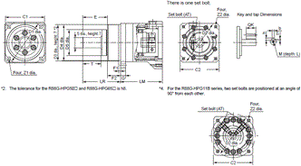
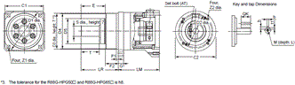
Note: 4. The standard shaft type is a shaft with key and tap. (The key is temporarily assembled to the shaft.)
Note: 5. Take care so that the surface temperature of the Decelerator does not exceed 90°C.
Decelerator for Flat Servomotors
| Model (R88G-) | Rated speed | Rated torque | Ra- tio | Maxi- mum mo- men- tary speed | Maxi- mum mo- men- tary torque | Decel- erator inertia | Al- lowable radial load | Al- lowable thrust load | Weight | ||
|---|---|---|---|---|---|---|---|---|---|---|---|
| r/min | Nm | % | r/min | Nm | kg·m2 | N | N | kg | |||
| 100 W | 1/5 | VRXF05B100PCJ | 600 | 1.44 | 90 | 1000 | 4.05 (3.83) | 6.00× 10⁻⁶ | 392 | 196 | 0.70 |
| 1/9 | VRXF09B100PCJ | 333 | 2.59 | 90 | 556 | 7.29 (6.89) | 5.00× 10⁻⁶ | 441 | 220 | 0.70 | |
| 1/15 | VRXF15B100PCJ | 200 | 4.13 | 86 | 333 | 11.61 (10.97) | 5.70× 10⁻⁶ | 588 | 294 | 0.90 | |
| 1/25 | VRXF25B100PCJ | 120 | 6.88 | 86 | 200 | 19.35 (18.28) | 5.50× 10⁻⁶ | 686 | 343 | 0.90 | |
| 200 W | 1/5 | VRXF05B200PCJ | 600 | 2.94 | 92 | 1000 | 8.37 (8.56) | 1.50× 10⁻⁵ | 392 | 196 | 0.90 |
| 1/9 | VRXF09C200PCJ | 333 | 4.78 | 83 | 556 | 13.60 (13.89) | 2.70× 10⁻⁵ | 931 | 465 | 2.00 | |
| 1/15 | VRXF15C200PCJ | 200 | 8.26 | 86 | 333 | 23.48 (23.99) | 3.02× 10⁻⁵ | 1176 | 588 | 2.40 | |
| 1/25 | VRXF25C200PCJ | 120 | 13.76 | 86 | 200 | 39.13 (39.99) | 2.90× 10⁻⁵ | 1323 | 661 | 2.40 | |
| 400 W | 1/5 | VRXF05C400PCJ | 600 | 5.72 | 88 | 1000 | 15.84 | 3.70× 10⁻⁵ | 784 | 392 | 2.00 |
| 1/9 | VRXF09C400PCJ | 333 | 10.30 | 88 | 556 | 28.51 | 2.70× 10⁻⁵ | 931 | 465 | 2.00 | |
| 1/15 | VRXF15C400PCJ | 200 | 17.36 | 89 | 333 | 48.06 | 3.02× 10⁻⁵ | 1176 | 588 | 2.40 | |
| 1/25 | VRXF25C400PCJ | 120 | 28.93 | 89 | 200 | 80.10 | 2.90× 10⁻⁵ | 1323 | 661 | 2.40 | |
Note: 1. The values inside parentheses ( ) are those when using a 100-V motor.
Note: 2. The value given for the Decelerator inertia is the Servomotor shaft conversion value.
Note: 3. The protective structure rating of the Servomotor combined with the Decelerator is IP44.
(Excluding Decelerator and Servomotor connecting parts.)
Note: 4. The value given for the allowable radial load is the value at the center of the shaft (T/2).
Note: 5. The standard shaft type is a shaft with key and tap. (The key is temporarily assembled to the shaft.)
Note: 6. Take care so that the surface temperature of the Decelerator does not exceed 90°C.
Encoder, External Regeneration Resistors, Reactor and Parameter Unit Specifications
Encoder Specifications
| Item | Specifications |
|---|---|
| Encoder system | Optical encoder (incremental encoder) |
| No. of output pulses | Phases A and B: 2,500 pulses/rotation, Phase Z: 1 pulse/rotation |
| Power supply voltage | 5 V ± 5% |
| Power supply current | 180 mA (max.) |
| Output signals | +S, - S |
| Output interface | EIA RS-485 compliance |
| Duplex serial communications data |
External Regeneration Resistors Specifications
| Model | Re- sistance | Nominal capacity | Regeneration absorption for 120 °C temperature rise | Heat radiation condition | Thermal switch output specifications |
|---|---|---|---|---|---|
| R88A-RR08050S | 50 Ω | 80 W | 20 W | Aluminum 250 × 250, Thickness: 3.0 | Operating temperature: 150°C±5%, NC contact, Rated output: 30 VDC, 50 mA max. |
| R88A-RR080100S | 100 Ω | 80 W | 20 W | Aluminum 250 × 250, Thickness: 3.0 | Operating temperature: 150°C±5%, NC contact, Rated output: 30 VDC, 50 mA max. |
| R88A-RR22047S1 | 47 Ω | 220 W | 70 W | Aluminum 350 × 350, Thickness: 3.0 | Operating temperature: 150°C±5%, NC contact, Rated output (resistive load): 250 VAC, 0.2 A max. 42 VDC, 0.2 A max. (minimum current: 1 mA) |
Reactor Specifications
| Reactor type | Specifications | |||
|---|---|---|---|---|
| Model | Rated current (A) | Inductance (mH) | Weight (kg) | |
| Single-phase Reactors | 3G3AX-DL2002 | 1.6 A | 21.4 mH | 0.8 kg |
| 3G3AX-DL2004 | 3.2 A | 10.7 mH | 1.0 kg | |
| 3G3AX-DL2007 | 6.1 A | 6.75 mH | 1.3 kg | |
| Three-phase Reactor | 3G3AX-AL2025 | 10 A | 2.8 mH | 2.8 kg |
Parameter Unit Specifications
General Specifications
| Item | Specifications |
|---|---|
| Operating ambient temperature Operating ambient humidity | 0 to 55 °C 90% max. (with no condensation) |
| Storage ambient temperature Storage ambient humidity | - 20 to 80 °C 90% max. (with no condensation) |
| Storage and operating atmosphere | No corrosive gases |
| Vibration resistance | 5.9 m/s2 max. |
Performance Specifications
| Item | Specifications | |
|---|---|---|
| Type | Hand-held | |
| Cable length | 1.5 m | |
| Connectors | Mini DIN 8-pin MD connector | |
| Display | 7-segment LED | |
| External dimensions | 62 × 114 × 15 mm (W × H × D) | |
| Weight | Approx. 0.1 kg (including cable that is provided) | |
| Communications specifications | Standard | RS-232 |
| Communications method | Asynchronous (ASYNC) | |
| Baud rate | 9,600 bps | |
| Start bits | 1 bit | |
| Data | 8 bits | |
| Parity | None | |
| Stop bits | 1 bit | |
last update: December 25, 2018
OMRON R88M-G, R7D-BP dimension
R88M-G, R7D-BP AC Servomotors and SMARTSTEP 2-series Servo Drives with Pulse String Inputs/Dimensionslast update: October 2, 2017
(Unit: mm)
Servo Drives
50 W/100 W/200 W
R7D-BPA5L
R7D-BP01L
R7D-BP01H
R7D-BP02H
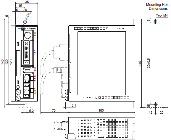
200 W/400 W
R7D-BP02L
R7D-BP02HH
R7D-BP04H

Servomotors
3,000-r/min Cylindrical Servomotors
50 W/100 W
[Without brake]
R88M-G05030H (-S2), R88M-G10030L (-S2), R88M-G10030H (-S2)
[With brake]
R88M-G05030H (-S2), R88M-G10030L (-S2), R88M-G10030H (-S2)
200 W/400 W
[Without brake]
R88M-G20030L (-S2), R88M-G20030H (-S2), R88M-G40030H (-S2)
[With brake]
R88M-G20030L-B (S2), R88M-G20030H-B (S2), R88M-G40030H-B (S2)
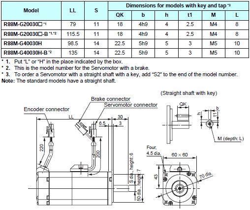
3,000-r/min Flat Servomotors
100 W/200 W/400 W
[Without brake]
R88M-GP10030L (-S2), R88M-GP10030H (-S2), R88M-GP20030L (-S2)
R88M-GP20030H (-S2), R88M-GP40030H (-S2)
[With brake]
R88M-GP10030L-B (S2), R88M-GP10030H-B (S2), R88M-GP20030L-B (S2)
R88M-GP20030H-B (S2), R88M-GP40030H-B (S2)
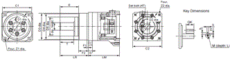
Decelerators
Backlash: 3 Arcminutes Max.
<Cylinder Type>
3,000-r/min servomotors (50 to 400 W)
Outline Drawings 1
Outline Drawings 2
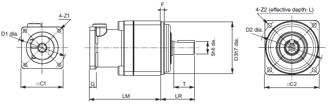
<Flat Servomotors>
3,000-r/min servomotors (100 to 400 W)
Outline Drawings
Backlash: 15 Arcminutes Max.
<Cylinder Type>
3,000-r/min servomotors (50 to 400 W)
Outline Drawings
<Flat Servomotors>
3,000-r/min servomotors (100 to 400 W)
Outline Drawings
Parameter Unit
R88A-PR02G
DIN Rail Mounting Unit
R7A-DIN01B
External Regeneration Resistor
R88A-RR22047S1
R88A-RR08050S
R88A-RR080100S
Reactor
3G3AX-DL2002
3G3AX-DL2004
3G3AX-DL2007
3G3AX-AL2025
last update: October 2, 2017
- NO. R88M-G, R7D-BP
- TYPE:Servomotors / Servo Drivers Copyright Statement Copyright Statement
- DATE:2021-06-11
- Associated products:
R88M-G, R88D-GT G-series AC Servomotors/Servo Drives with General-purpose Pulse-string or Analog Inputs/Features R88M-KE, R88D-KP G5-series Pulse Train Input Type AC Servomotors/Servo Drives/Features