OMRON G9SX-LMSafety Components/ Safety Units / Safety Relay Units/G9SX-series Flexible Safety Units
OMRON G9SX-LM Safety Components
OMRON G9SX-LM Dimensions
/Images/l_1986-25-118889-198x198.jpglast update: November 13, 2017
Applicable to Various Systems, Including Servomotors
PLd/Safety Category 3(ISO13849-1)

1. Monitoring with Proximity Sensors
A redundant safety system can be configured by using two E2E Proximity Sensors. The fault diagnosis function of the G9SX-LM provides a high level of safety.
* Use only the DC 3-wire PNP type E2E.

2. Speed Monitoring Matched to the Function for Each Operating Mode
In normal operating mode, standstill is monitored to unlock the door.
In maintenance mode, low-speed operation is monitored to allow maintenance work.

3. Applicable to Servomotors
Because the drive rotation is directly monitored, the G9SX-LM can also be used with Servomotors.
last update: November 13, 2017
Purchase the OMRON G9SX-series Flexible Safety Units Please fill in the following
If you have just landed here, this product OMRON G9SX-LM Safety Components,Safety Components is offered online by Tianin FLD Technical Co.,Ltd. This is an online store providing Safety Components at wholesale prices for consumers. You can call us or send enquiry, we would give you the prices, packing,deliverty and more detailed information on the G9SX-LM We cooperate with DHL,TNT,FEDEX,UPS,EMS,etc.They guarantee to meet your needs in terms of time and money,even if you need your OMRON G9SX-LMSafety Components tomorrow morning (aka overnight or next day air) on your desk, 2, 3 days or more.Note to international customers, YES, we ship worldwide.
G3ZA Multi-channel Power Controller/Features
E2K-L Liquid Level Sensor/Features
CJ1W-V680C11 / V680C12 CJ Series ID Sensor Unit/Features
Cobra 500 SCARA Robots/Features
S8VM Switch Mode Power Supply (15/30/50/100/150/300/600/1,500-W Models)/Features
OMRON G9SX-LM dimension
G9SX-LM Low-speed Monitoring Unit/Dimensionslast update: November 12, 2012
(Unit: mm)
Low-speed Monitoring Unit
G9SX-LM224-F10-[]
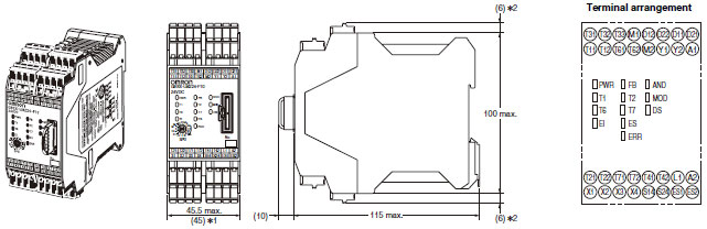
*1 Typical dimension
*2 For -RC terminal type only.
Note: Above outline drawing is for -RC terminal type.
Expansion Unit
G9SX-EX401-[]
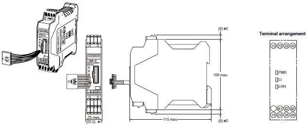
*1 Typical dimension
*2 For -RC terminal type only.
Note: Above outline drawing is for -RC terminal type.
last update: November 12, 2012
OMRON G9SX-LM lineup
G9SX-LM Low-speed Monitoring Unit/Lineuplast update: September 24, 2012
Low-speed Monitoring Unit
| Safety instantaneous output | Safety slow- speed/stopping detection output | Auxiliary output | Maximum set threshold | Rated voltage | Terminal block type | Model |
|---|---|---|---|---|---|---|
| 2 (Semiconductor) | 2 (Semiconductor) | 4 (Semiconductor) | 10 Hz | 24 VDC | Screw terminals | G9SX-LM224-F10-RT |
| Spring-cage terminals | G9SX-LM224-F10-RC |
Expansion Unit
| Safety outputs | Auxiliary outputs | OFF-delay time | Rated voltage | Terminal block type | Model | |
|---|---|---|---|---|---|---|
| Instantaneous | OFF-delayed | |||||
| 4a (contact) | 0 | 1 (Semiconductor) | -- | 24 VDC | Screw terminals | G9SX-EX401-RT |
| Spring-cage terminals | G9SX-EX401-RC | |||||
last update: September 24, 2012
OMRON G9SX-LM catalog
G9SX-LM Low-speed Monitoring Unit/Catalog- Catalog
- Manual
- CAD
English
Global Edition
| Catalog Name | Catalog Number [size] | Last Update | |
|---|---|---|---|
| | J172-E1-02 [697KB] | Dec 11, 201720171211 | G9SX-LM Data Sheet |
| | J170-E1-03 [1485KB] | Nov 13, 201720171113 | G9SX-SM/LM Catalog |
OMRON G9SX-LM specification
G9SX-LM Low-speed Monitoring Unit/Specificationslast update: December 11, 2017
Ratings
Power input
| Model | G9SX-LM224-[] | G9SX-EX401-[] |
|---|---|---|
| Rated supply voltage | 24 VDC | |
| Operating voltage range | -15% to +10% of rated supply voltage | |
| Power consumption * | 5 W max. | 2 W max. |
* Power consumption of loads not included.
Inputs
| Model | G9SX-LM224-[] |
|---|---|
| Safety input Enabling input Feedback/reset input Mode selector input | Operating voltage: 20.4 VDC to 26.4 VDC Internal impedance: Approx. 2.8 kΩ * |
| Rotation detection input | Operating voltage: 20.4 VDC to 26.4 VDC Internal impedance: Approx. 2.8 kΩ * Frequency input range: 1 kHz max. |
* Provide a current equal to or higher than that of the minimum applicable load of the connected input control device.
Outputs
| Model | G9SX-LM224-[] |
|---|---|
| Safety instantaneous output *1 | Source output (PNP compatible) Load current: 0.8 A DC max. * 2 |
| Safety speed detection output *1 | Source output (PNP compatible) Load current: 0.3 A DC max. |
| Auxiliary output | Source output (PNP compatible) Load current: 100 mA DC max. |
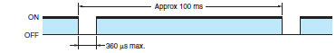
*1. While safety instantaneous outputs and safety speed detection outputs are in the ON state, the following pulse signal
is output continuously for output circuit diagnosis.
When using these safety outputs as input signals to control devices (i.e. Programmable Controllers), consider the
pulse signal shown below.
*2. The following derating is required when Units are mounted side-by-side.
G9SX-LM[]: 0.4 A DC max. load current
Expansion Unit
| Model | G9SX-EX-[] |
|---|---|
| Rated load | 250 VAC, 3A /30 VDC, 3A (resistive load) |
| Rated carry current | 3A |
| Maximum switching voltage | 250 VAC, 125 VDC |
Characteristics
| Model | G9SX-LM224 | G9SX-EX401 | |
|---|---|---|---|
| Over-voltage category (IEC/EN60664-1) | II | II (Safety relay outputs 13 to 43 and 14 to 44: III) | |
| Operating time (OFF to ON state) *1 *2 *5 | 50 ms max. (Safety input: ON, Enabling input: ON) 100 ms max. (Logical AND connection input: ON) | 30 ms max. *6 | |
| Response time (ON to OFF state) *1 *5 | 15 ms max. | 10 ms max. *6 | |
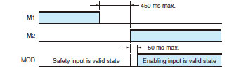
| Allowable time for switching Mode selector inputs *3 | 450 ms max. | -- | |
| Mode selector input response time *4 | 50 ms max. | -- | |
| ON-state residual voltage | 3.0 V max. (safety instantaneous outputs, safety speed detection outputs, and auxiliary outputs) | ||
| OFF-state leakage current | 0.1 mA max. (safety instantaneous outputs, safety speed detection outputs, and auxiliary outputs) | ||
| Maximum cable length for logical connection inputs and Safety inputs | 100 m max. (External connection impedance: 100 Ω max. and 10 nF max.) | ||
| Reset input time | 100 ms min. | ||
| Accuracy tolerance of low speed detection frequency | Within minus 10% of the set value | -- | |
| Insulation resistance | Between logical AND connection terminals, and power supply input terminals and other input and output terminals connected together | 20 MΩ min., 250 VDC megger | -- |
| Between all terminals connected together and DIN rail | 100 MΩ min., 500 VDC megger | ||
| Dielectric strength | Between logical AND connection terminals, and power supply input terminals and other input and output terminals connected together | 500 VAC for 1 min | -- |
| Between all terminals connected together and DIN rail | 1,200 VAC for 1 min | ||
| Between different poles of outputs | -- | 1,200 VAC for 1 min | |
| Between safety relay outputs connected together and other terminals connected together | 2,200 VAC for 1 min | ||
| Vibration resistance | Frequency: 10 to 55 to 10 Hz, 0.375-mm single amplitude (0.75-mm double amplitude) | ||
| Mechanical shock resistance | Destruction | 300 m/s2 | |
| Malfunction | 100 m/s2 | ||
| Durability | Electrical | -- | 100,000 cycles min. (rated load, switching frequency: 1,800 cycles/hour) |
| Mechanical | -- | 5,000,000 cycles min. (switching frequency: 7,200 cycles/hour) | |
| Ambient temperature | -10 to 55°C (no icing or condensation) | ||
| Ambient humidity | 25 % to 85 % | ||
| Terminal tightening torque *7 | 0.6 Nm | ||
| Weight | Approx. 240 g | Approx. 165 g | |
*1. When two or more Units are connected by logical AND, the operating time and response time are the sum total of the
operating times and response times, respectively, of all the Units connected by logical AND.
*2. Represents the time required to turn ON safety instantaneous outputs when required conditions are met.
*3. Represents the time allowed for switching mode selector inputs. If it exceeds 450 ms, G9SX-LM[] will detect it as az failure.
*4. Represents the time required for safety inputs/enabling inputs to be switched following a switch of mode selector
inputs.
*5. Operating time and response time do not include the frequency detection time and the time affected by the
characteristics of proximity sensors.
For response performance of the entire system, see "(5) Response performance regarding speed detection".
*6. The value of the operating time and response time of the connected Low-speed Monitoring Unit is not included.
*7. For the G9SX-[]-RT (with screw terminals)
Logical AND Connection
| Model | G9SX-LM224 | G9SX-EX401-[] |
|---|---|---|
| Number of Units connected per logical AND output | 4 units max. | -- |
| Total number of Units connected by logical AND * | 20 units max. | -- |
| Number of Units connected in series by logical AND | 5 units max. | -- |
| Max. number of Expansion Units connected | -- | 5 units max. |
| Maximum cable length for logical AND input | 100 m max. | -- |
* The number of G9SX-EX401-[] Expansion Units not included.
last update: December 11, 2017
- NO. G9SX-LM
- TYPE:Safety Units / Safety Relay Units G9SX-series Flexible Safety Units
 Copyright Statement
 - DATE:2021-06-13
- Associated products:
G9SX-SM Standstill Monitoring Unit/Features G9SA Safety Relay Unit/Features