OMRON H8BM-RControl Components/ Counters/Multi-counters
OMRON H8BM-R Control Components
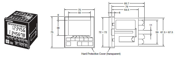
OMRON H8BM-R Dimensions
/Images/l_230-25-118937-198x198.jpglast update: December 19, 2013
• Provides up to nine counters or accumulative timers. (Counter and timer functions can be used at the same time.)
• Individual forecast outputs to indicate maintenance timing.
• Pre-forecast display and machine stoppage output provided.
• IP54 oil-proof type at setting area for resistance to oil and water.
• Separate digit keys to easily change settings.
• Compact, short-body: 72 × 72 × 79 mm (DIN).
• Key protection function prevents incorrect operation.
• Multiple outputs: NPN/PNP.
• Directly connectable to 2-wire DC sensors.
• Complies with UL and CSA.
last update: December 19, 2013
Purchase the OMRON Multi-counters Please fill in the following
If you have just landed here, this product OMRON H8BM-R Control Components,Control Components is offered online by Tianin FLD Technical Co.,Ltd. This is an online store providing Control Components at wholesale prices for consumers. You can call us or send enquiry, we would give you the prices, packing,deliverty and more detailed information on the H8BM-R We cooperate with DHL,TNT,FEDEX,UPS,EMS,etc.They guarantee to meet your needs in terms of time and money,even if you need your OMRON H8BM-RControl Components tomorrow morning (aka overnight or next day air) on your desk, 2, 3 days or more.Note to international customers, YES, we ship worldwide.
R88M-K, R88D-KT G5-series AC Servomotors/Servo Drives with General-purpose Pulse Train or Analog ...
PYF[][]S / P2RF-[][]-S Screwless Clamp Terminal Sockets/Features
E3Z-LS Distance-settable Photoelectric Sensor/Features
D4SL-N, D4SL-NSK10-LK[] Guard Lock Safety-door Switch/D4SL-N-mounting Slide Key/Features
G3NA Solid State Relays/Features
OMRON H8BM-R specification
H8BM-R Multi-maintenance Counter/Timer (DIN 72 x 72)/Specificationslast update: August 03, 2015
Specifications
| Model | H8BM-RA/RB | H8BM-RAD/RBD |
|---|---|---|
| Classification | 3-stage setting | 1-stage setting |
| Mounting method | Flush mounting | |
| External connections | Screw terminals | |
| Degree of protection | IP54 oil-proof type (case front) | |
| Input mode | Up | |
| Output mode | F mode (Operation continues even when setting is reached.) | |
| Reset system | External, manual resets | |
| Timer operation | Yes | |
| Input method | Voltage inputs: High and low signal voltages (count, reset, short, counter No. selection, I/O inhibit) | |
| Control output | No-contact outputs: RUN, forecast, machine stoppage | No-contact outputs: RUN, forecast |
| Display | Count, preset value, counter number, and error codes displayed on 7-segment LCD Mode, reset, I/O inhibit, re-monitor modes, and key protection displayed on LCD characters Output indication on LCD characters and LEDs | |
| LCD with backlight | Yes | |
| Built-in counter number | 9 (counters 1 to 9) *1 | |
| Preset stage | 3-stage *2 | 1-stage *3 |
| Digits | Forecast value: 6 digits (999999) Pre-forecast value: -5 digits *4 Machine stoppage: +5 digits *5 | Forecast value: 6 digits (999999) |
| Time ranges | Forecast value: 99999.9 h (0.1 h or longer)/ 99999.9 s (0.1 s or longer) Pre-forecast value: -9999.9 h/-9999.9 s *4 Machine stoppage: +9999.9 h/+9999.9 s *5 | Forecast value: 99999.9 h (0.1 h or longer)/ 99999.9 s (0.1 s or longer) |
| Memory backup | EEPROM (Data can be written 100,000 times.), Backup time for power interruption: Approx. 10 years | |
*1. Each channel operates on a separate I/O.
*2. The 3-stage are pre-forecast, forecast, and machine stoppage.
Pre-forecast: Displayed only on LCD (no external output is provided).
Forecast: Displayed on LCD and LED and output (output for each counter).
Machine stoppage: Displayed on LCD and LED and output (output when the count value of one or more of counters 1
to 9 has reached its machine stoppage value).
*3. This Counter operates on the forecast value only.
*4. The pre-forecast value is set as a negative offset in respect to the forecast value.
*5. The machine stoppage value is set as a positive offset in respect to the forecast value.
Ratings
| Rated supply voltage | 24 VDC |
|---|---|
| Operating voltage range | 85% to 110% of rated supply voltage *1 |
| Power consumption | Approx. 1.7 W (at 26.4 VDC) |
| Max. counting speed | 30 Hz for count inputs 1 to 7, Switchable between 30 Hz and 500 Hz for count inputs 8 and 9 |
| Min. counting input signal width | Count inputs 1 to 7: 16.7 ms (ON:OFF = 1:1) Count inputs 8 and 9: 16.7 ms/1 ms selectable (ON:OFF = 1:1) Reset input: 100 ms max. Short input: 75 ms max. Counter number selection input: 30 ms max. I/O inhibit input: 16.7 ms max. |
| One-shot time | 20 ms *2 |
| Count, reset, short, counter number selection, and I/O inhibit input | Voltage input High level: 16 to 26.4 VDC Low level: 0 to 3 VDC (input resistance: approx. 2.2 kΩ) |
| Control output | Open-collector output: 100 mA max. at 30 VDC max. |
| Surrounding air temperature | -10 to +55°C (with no icing or condensation) |
| Ambient storage temperature | -25 to +65°C (with no icing or condensation) |
| Ambient operating humidity | 25% to 85% |
| Case color | Dark gray (Munsell 5Y3/1) |
*1. Ripple content: 20% max.
*2. This signal is output as a carry signal when the Counter is used as a total counter.
Characteristics
| Insulation resistance | 100 MΩ min. (at 500 VDC) (between current-carrying terminals and exposed non- current-carrying metal parts) | |
|---|---|---|
| Dielectric strength voltage | 1,000 VAC, 50/60 Hz for 1 min (between currentcarrying terminals and exposed non- current-carrying metal parts) | |
| Impulse withstand voltage | 1 kV (between power terminals) 1.5 kV (between current-carrying terminals and exposed non-current-carrying metal parts) | |
| Noise immunity | ±480 kV (between power terminals) and ±480 V (between input terminals), square-wave noise by noise simulator (pulse width: 100 ns/1 μs, 1-ns rise) | |
| Static immunity | Malfunction: 8 kV; destruction: 15 kV | |
| Vibration resistance | Destruction | 10 to 55 Hz with 0.75-mm single amplitude, 2 hours each in three directions |
| Malfunction | 10 to 55 Hz with 0.5-mm single amplitude, 10 minutes each in three directions | |
| Shock resistance | Destruction | 300 m/s2 3 times each in 6 directions |
| Malfunction | 200 m/s2 3 times each in 6 directions | |
| Weight | Approx. 250 g (Counter only) | |
Applicable Standards
| Safety standards | UL508 (See note 1.)/CSA C22.2 No.14 EN61326 |
|---|---|
| EMC | (EMI) EN61326-1 (See note 2.) Emission Enclosure: EN61326-1 (EN55011 Group 1 Class A) Emission AC Mains: EN61326-1 (EN55011 Group 1 Class A) (EMS) EN61326-1 (See note 2.) Immunity ESD: EN61326-1 (EN61000-4-2): Contact discharge: 4 kV, air discharge: 8 kV Radiated electromagnetic field immunity: EN61326-1 (EN61000-4-3): 10 V/m (Amplitude modulated, 80 MHz to 1 GHz, 1,400 to 2,000 MHz) 10 V/m (Pulse-modulated, 900 MHz ±5 MHz) Immunity Burst: EN61326-1 (EN61000-4-4): 2 kV power-line, 1 kV I/O signal-line Immunity Surge: EN61326-1 (EN61000-4-5): 1 kV line to line (power line), 2 kV line to ground (power line) Immunity Conducted Disturbance: EN61326-1 (EN61000-4-6): 10 V (0.15 to 80 MHz) |
Note 1. Attach a waterproof cover of Y92A-72N.
2. Industrial electromagnetic environment (EN/IEC 61326-1 Table 2)
last update: August 03, 2015
OMRON H8BM-R catalog
H8BM-R Multi-maintenance Counter/Timer (DIN 72 x 72)/Catalog- Catalog
- Manual
- CAD
English
Global Edition
| Catalog Name | Catalog Number [size] | Last Update | |
|---|---|---|---|
| | - [2460KB] | Sep 30, 198919890930 | H8BM-R Data Sheet |
OMRON H8BM-R lineup
H8BM-R Multi-maintenance Counter/Timer (DIN 72 x 72)/Lineuplast update: August 03, 2015
Multi-maintenance Counter/Timer
| Preset stage | Nameplate lettering | Model |
|---|---|---|
| 3-stage setting | Japanese | H8BM-RA DC24 |
| English | H8BM-RB DC24 | |
| 1-stage setting | Japanese | H8BM-RAD DC24 |
| English | H8BM-RBD DC24 |
Accessories (Order Separately)
| Name | Model |
|---|---|
| Hard Protective Cover *1 | Y92A-72C |
| Rubber Packing *1 | Y92S-25 |
| Short-circuit plate *2 | Y92S-26 |
*1. A Hard Protective Cover and Rubber Packing are supplied with the Counter.
*2. The H8BM-R[] is provided with short input as standard to achieve a Multi-stage Counter without having to use a
short-circuit plate and external wiring.
last update: August 03, 2015
OMRON H8BM-R dimension
H8BM-R Multi-maintenance Counter/Timer (DIN 72 x 72)/Dimensionslast update: November 16, 2012
Counter
H8BM-R
last update: November 16, 2012
- NO. H8BM-R
- TYPE:Counters Multi-counters
 Copyright Statement
 - DATE:2021-06-17
- Associated products:
H7E[]-N Self-powered Totalizer/Features K3HB-X Process Indicator/Features