OMRON G3NARelays/ Solid-state Relays/For Heater Control
OMRON G3NA Relays
OMRON G3NA Dimensions
/Images/l_992-25-118861-198x198.jpglast update: December 19, 2013
• AC Output Relays with 75-A and 90-A output currents have been added to the G3NA Series.
• All models feature the same compact dimensions to provide a uniform mounting pitch.
• Built-in varistor effectively absorbs external surges. (except G3NA-D210B)
• Operation indicator enables monitoring operation.
• Protective cover for greater safety.
• Standard models certified by UL and CSA and -UTU models by TÜV. (except G3NA-410B, G3NA-420B, and G3NA-440B(-2))
last update: December 19, 2013
Purchase the OMRON For Heater Control Please fill in the following
If you have just landed here, this product OMRON G3NA Relays,Relays is offered online by Tianin FLD Technical Co.,Ltd. This is an online store providing Relays at wholesale prices for consumers. You can call us or send enquiry, we would give you the prices, packing,deliverty and more detailed information on the G3NA We cooperate with DHL,TNT,FEDEX,UPS,EMS,etc.They guarantee to meet your needs in terms of time and money,even if you need your OMRON G3NARelays tomorrow morning (aka overnight or next day air) on your desk, 2, 3 days or more.Note to international customers, YES, we ship worldwide.
K6CM Motor Condition Monitoring Device/Features
G2RV Slim Relay/Features
CRT1-TS04T / TS04P Temperature Input Units/Features
SRT2-ID16P / OD16P Remote I/O Modules/Features
XW2N Connector-Terminal Block Conversion Unit with 16-input e-CON Terminal Block with Common/Feat...
OMRON G3NA lineup
G3NA Solid State Relays/Lineuplast update: November 15, 2012
| Isolation | Zero cross function | Indicator | Applicable output load *1 | Rated input voltage | Model |
|---|---|---|---|---|---|
| Phototriac Coupler | Yes | Yes (Yellow) | 5 A at 24 to 240 VAC *2 | 5 to 24 VDC | G3NA-205B DC5-24 |
| Photocoupler | 100 to 120 VAC | G3NA-205B AC100-120 | |||
| 200 to 240 VAC | G3NA-205B AC200-240 | ||||
| Phototriac Coupler | 10 A at 24 to 240 VAC *2 | 5 to 24 VDC | G3NA-210B DC5-24 | ||
| Photocoupler | 100 to 120 VAC | G3NA-210B AC100-120 | |||
| 200 to 240 VAC | G3NA-210B AC200-240 | ||||
| Phototriac Coupler | 20 A at 24 to 240 VAC *2 | 5 to 24 VDC | G3NA-220B DC5-24 | ||
| Photocoupler | 100 to 120 VAC | G3NA-220B AC100-120 | |||
| 200 to 240 VAC | G3NA-220B AC200-240 | ||||
| Phototriac Coupler | 40 A at 24 to 240 VAC *2 | 5 to 24 VDC | G3NA-240B DC5-24 | ||
| Photocoupler | 100 to 120 VAC | G3NA-240B AC100-120 | |||
| 200 to 240 VAC | G3NA-240B AC200-240 | ||||
| Phototriac Coupler | 75 A at 24 to 240 VAC *2 | 5 to 24 VDC | G3NA-275B-UTU-2 DC5-24 | ||
| Photocoupler | 100 to 120 VAC | G3NA-275B-UTU-2 AC100-240 | |||
| Phototriac Coupler | 90 A at 24 to 240 VAC *2 | 5 to 24 VDC | G3NA-290B-UTU-2 DC5-24 | ||
| Photocoupler | 100 to 240 VAC | G3NA-290B-UTU-2 AC100-240 | |||
| Yes | 10 A at 200 to 480 VAC | 5 to 24 VDC | G3NA-410B DC5-24 | ||
| 100 to 240 VAC | G3NA-410B AC100-240 | ||||
| 20 A at 200 to 480 VAC | 5 to 24 VDC | G3NA-420B DC5-24 | |||
| 100 to 240 VAC | G3NA-420B AC100-240 | ||||
| 40 A at 200 to 480 VAC | 5 to 24 VDC | G3NA-440B-2 DC5-24 | |||
| 100 to 240 VAC | G3NA-440B-2 AC100-240 | ||||
| 50 A at 200 to 480 VAC *2 | 5 to 24 VDC | G3NA-450B-2 DC5-24 | |||
| 75 A at 200 to 480 VAC *2 | 5 to 24 VDC | G3NA-475B-UTU-2 DC5-24 | |||
| 100 to 240 VAC | G3NA-475B-UTU-2 AC100-240 | ||||
| 90 A at 200 to 480 VAC *2 | 5 to 24 VDC | G3NA-490B-UTU-2 DC5-24 | |||
| 100 to 240 VAC | G3NA-490B-UTU-2 AC100-240 | ||||
| --- | 10 A at 5 to 200 VDC | 5 to 24 VDC | G3NA-D210B DC5-24 | ||
| 100 to 240 VAC | G3NA-D210B AC100-240 |
To order a TÜV-certified model for G3NA-205BN/210B/220B/240B/D210B, add “-UTU” to the model number.
*1. The applicable load is the value for when the SSR is used with silicon grease applied to the specified heat sink. The
applicable load depends on the ambient temperature. Refer to Load Current vs. Ambient Temperature in
Engineering Data on Catalog.
*2. Loss time increases under 75 VAC. (Refer to Catalog.) Confirm operation with the actual load.
Accessories (Order Separately)
One-touch Mounting Plates
| Model |
|---|
| R99-12 FOR G3NA |
Mounting Bracket
| Model | Applicable SSR |
|---|---|
| R99-11 | G3NA-240B, G3NA-440B(-2) |
Heat Sinks
Slim Models Enabling DIN-track Mounting
| Model | Applicable SSR |
|---|---|
| Y92B-N50 | G3NA-205B, G3NA-210B, G3NA-D210B, G3NA-410B, G3NA-210T(L) |
| Y92B-N100 | G3NA-220B, G3NA-420B, G3NA-220T(L) |
| Y92B-N150 | G3NA-240B, G3NA-440B-2 |
| Y92B-P250 | G3NA-450B-2 |
| Y92B-P250NF * | G3NA-275B-UTU-2, G3NA-290B-UTU-2, G3NA-475B-UTU-2, G3NA-490B-UTU-2 |
Low-cost Models
| Model | Applicable SSR |
|---|---|
| Y92B-A100 | G3NA-205B, G3NA-210B, G3NA-D210B, G3NA-220B, G3NA-410B, G3NA-420B |
| Y92B-A150N | G3NA-240B-2, G3NA-440B-2 |
| Y92B-A250 | G3NA-440B-2 |
last update: November 15, 2012
OMRON G3NA specification
G3NA Solid State Relays/Specificationslast update: November 15, 2012
Ratings
Input (at an Ambient Temperature of 25°C)
| Model | Rated voltage | Operating voltage | Impedance *1 | Voltage level | |
|---|---|---|---|---|---|
| Must operate voltage | Must release voltage | ||||
| G3NA-2[][]B | 5 to 24 VDC | 4 to 32 VDC | 7 mA max. *2 | 4 VDC max. | 1 VDC min. |
| 100 to 120 VAC | 75 to 132 VAC | 36 kΩ±20% *4 | 75 VAC max. *3 | 20 VAC min. *3 | |
| 200 to 240 VAC | 150 to 264 VAC | 72 kΩ±20% | 150 VAC max. *3 | 40 VAC min. *3 *5 | |
| G3NA-4[][]B G3NA-D210B | 5 to 24 VDC | 4 to 32 VDC | 5 mA max. *2 | 4 VDC max. | 1 VDC min. |
| 100 to 240 VAC | 75 to 264 VAC | 72 kΩ±20% | 75 VAC max. | 20 VAC min. | |
| G3NA-275B-UTU-2 G3NA-290B-UTU-2 | 5 to 24 VDC | 4 to 32 VDC | 15 mA max. | 4 VDC max. | 1 VDC min. |
| 100 to 240 VAC | 75 to 264 VAC | 72 kΩ±20% | 75 VAC max. | 20 VAC min. | |
| G3NA-475B-UTU-2 G3NA-490B-UTU-2 | 5 to 24 VDC | 4 to 32 VDC | 7 mA max. | 4 VDC max. | 1 VDC min. |
| 100 to 240 VAC | 75 to 264 VAC | 72 kΩ±20% | 75 VAC max. | 20 VAC min. | |
rated at 100 to 120 VAC, the input impedance is measured at 120 VAC).
*2. With constant current input circuit system. The impedance for the G3NA-2[][]B-UTU is 15 mA max.
*3. Refer to Temperature Characteristics (for Must Operate Voltage and Must Release Voltage) in Engineering Data on
Catalog for further details.
*4. The G3NA-240B(-UTU) is 72kΩ±20%.
*5. The G3NA-240B(-UTU) is 20 VAC min.
Output
| Model | Rated load voltage | Load voltage range | Load current *1 | Inrush current | VDRM, VCEO (reference value) | |
|---|---|---|---|---|---|---|
| With heat sink *2 | Without heat sink | |||||
| G3NA-205B | 24 to 240 VAC | 19 to 264 VAC | 0.1 to 5 A (at 40°C) | 0.1 to 3 A (at 40°C) | 60 A (60 Hz, 1 cycle) | 600 V (VDRM) |
| G3NA-210B | 0.1 to 10 A (at 40°C) | 0.1 to 4 A (at 40°C) | 150 A (60 Hz, 1 cycle) | |||
| G3NA-220B | 0.1 to 20 A (at 40°C) | 0.1 to 4 A (at 40°C) | 220 A (60 Hz, 1 cycle) | |||
| G3NA-240B | 0.1 to 40 A (at 40°C) | 0.1 to 6 A (at 40°C) | 440 A (60 Hz, 1 cycle) | |||
| G3NA-410B | 200 to 480 VAC | 180 to 528 VAC | 0.2 to 10 A (at 40°C) | 0.2 to 4 A (at 40°C) | 150 A (60 Hz, 1 cycle) | 1,200 V (VDRM) |
| G3NA-420B | 0.2 to 20 A (at 40°C) | 0.2 to 4 A (at 40°C) | 220 A (60 Hz, 1 cycle) | |||
| G3NA-440B-2 | 0.2 to 40 A (at 40°C) | 0.2 to 6 A (at 40°C) | 440 A (60 Hz, 1 cycle) | |||
| G3NA-D210B | 5 to 200 VDC | 4 to 220 VDC | 0.1 to 10 A (at 40°C) | 0.1 to 4 A (at 40°C) | 20 A (10 ms) | 400 V (VCEO) |
| G3NA-275B-UTU-2 | 24 to 240 VAC | 19 to 264 VAC | 1 to 75 A (at 40°C) | 1 to 7 A (at 40°C) | 800 A (60 Hz, 1 cycle) | 600 V (VDRM) |
| G3NA-290B-UTU-2 | 1 to 90 A (at 40°C) | 1 to 7 A (at 40°C) | 1,000 A (60 Hz, 1 cycle) | |||
| G3NA-475B-UTU-2 | 200 to 480 VAC | 180 to 528 VAC | 1 to 75 A (at 40°C) | 1 to 7 A (at 40°C) | 800 A (60 Hz, 1 cycle) | 1,200 V (VDRM) |
| G3NA-490B-UTU-2 | 1 to 90 A (at 40°C) | 1 to 7 A (at 40°C) | 1,000 A (60 Hz, 1 cycle) | |||
under Engineering Data on Catalog.
*2. When an OMRON Heat Sink (refer to Options) or a heat sink of the specified size is used.
Characteristics
| Item | G3NA-205B G3NA-210B G3NA-220B | G3NA- 240B | G3NA-410B G3NA-420B G3NA-440B-2 G3NA-450B-2 | G3NA- D210B | G3NA-275B- UTU-2 G3NA-290B- UTU-2 | G3NA-475B- UTU-2 G3NA-490B- UTU-2 |
|---|---|---|---|---|---|---|
| Operate time | 1/2 of load power source cycle + 1 ms max. (DC input) 3/2 of load power source cycle + 1 ms max. (AC input) | 1 ms max. (DC input) 30 ms max. (AC input) | 1/2 of load power source cycle + 1 ms max. (DC input) 3/2 of load power source cycle + 1 ms max. (AC input) | |||
| Release time | 1/2 of load power source cycle + 1 ms max. (DC input) 3/2 of load power source cycle + 1 ms max. (AC input) | 5 ms max. (DC input) 30 ms max. (AC input) | 1/2 of load power source cycle + 1 ms max. (DC input) 3/2 of load power source cycle + 1 ms max. (AC input) | |||
| Output ON voltage drop | 1.6 V (RMS) max. | 1.8 V (RMS) max. | 1.5 V max. | 1.6 V (RMS) max. | 1.8 V (RMS) max. | |
| Leakage current | 5 mA max. (at 100 VAC) 10 mA max. (at 200 VAC) | 10 mA max. (at 200 VAC) 20 mA max. (at 400 VAC) | 5 mA max. (at 200 VDC) | 5 mA max. (at 100 VAC) 10 mA max. (at 200 VAC) | 10 mA max. (at 200 VAC) 20 mA max. (at 400 VAC) | |
| Insulation resistance | 100 MΩ min. (at 500 VDC) | |||||
| Dielectric strength | 2,500 VAC, 50/60 Hz for 1 min | 4,000 VAC, 50/60 Hz for 1 min | ||||
| Vibration resistance | Destruction: 10 to 55 to 10 Hz, 0.75-mm single amplitude (1.5-mm double amplitude) | |||||
| Shock resistance | Destruction: 1,000 m/s2 | |||||
| Ambient temperature | Operating: -30°C to 80°C (with no icing or condensation) Storage: -30°C to 100°C (with no icing or condensation) | |||||
| Ambient humidity | Operating: 45% to 85% | |||||
| Weight | Approx. 60 g | Approx. 70 g | Approx. 80 g | Approx. 70 g | Approx. 120 g | |
last update: November 15, 2012
OMRON G3NA dimension
G3NA Solid State Relays/Dimensionslast update: September 15, 2016
Relays
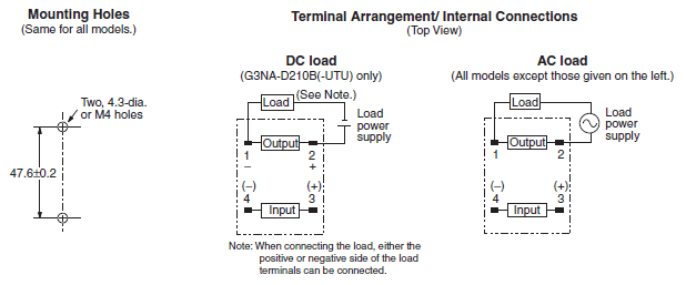
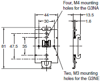
G3NA-D210B, G3NA-205B, G3NA-210B, G3NA-220B
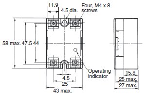
Note: The load can be connected to either the positive or negative side.
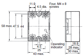
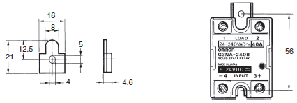
G3NA-240B, G3NA-275B-UTU-2, G3NA-290B-UTU-2,
G3NA-440B-2, G3NA-475B-UTU-2, G3NA-490B-UTU-2
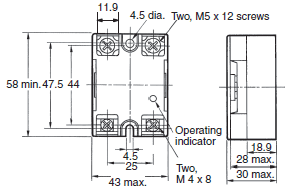
G3NA-410B, G3NA-420B
Options (Order Separately)
One-touch Mounting Plate
The One-touch Mounting Plate is used to mount the GN3A to a DIN Track.
R99-12 FOR G3NA (for the G3NA and G3NE)
Mounting Bracket
R99-11 (for the G3NA-240B, G3NA-440B-2)
Use Mounting Bracket R99-11 so that the G3NA-240B/-440B can be mounted with the same pitch as that of the G3N-240B.
Heat Sinks
Y92B-N50 Heat Sink (for the G3NA-205B, G3NA-210B, G3NA-D210B, G3NA-410B, G3NE-210T(L))
For surface mounting, a 30% derating of the load current is required (from the Load Current vs. Ambient Temperature graphs).
For mounting method, refer to "Precautions for Correct Use".
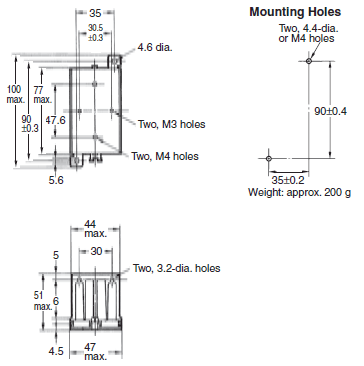
Weight: approx. 200 g
Y92B-N100 Heat Sink (for the G3NA-220B, G3NA-420B, G3NE-220T(L))
For surface mounting, a 30% derating of the load current is required (from the Load Current vs. Ambient Temperature graphs).
For mounting method, refer to "Precautions for Correct Use".
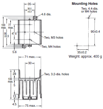
Weight: approx. 400 g
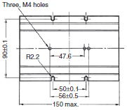
Y92B-N150 Heat Sink (for the G3NA-240B, G3NA-440B-2)
For surface mounting, a 30% derating of the load current is required (from the Load Current vs. Ambient Temperature graphs).
For mounting method, refer to "Precautions for Correct Use".
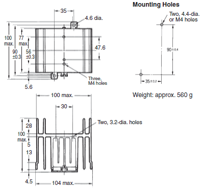
Weight: approx. 560 g
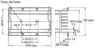
Y92B-P250NF Heat Sink (for the G3NA-275B-UTU(-2), G3NA-475B-UTU(-2), G3NA-290B-UTU(-2), G3NA-490B-UTU(-2))
For mounting method, refer to "Precautions for Correct Use".
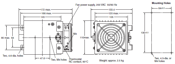
Weight: approx. 2.5 kg
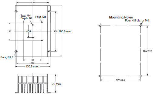
Y92B-P250
Y92B-A100 Heat Sink
(for the G3NA-205B, G3NA-210B, G3NA-220B, G3NA-410B, G3NA-420B, G3NA-D210B)
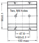
Weight: approx. 210 g
Y92B-A150N Heat Sink
(for the G3NA-240B, G3NA-440B-2)
Weight: approx. 310 g
Y92B-A250 Heat Sink
(for the G3NA-440B-2)
Weight: approx. 510 g
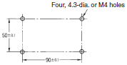
Mounting Holes
Y92B-A100
Y92B-A150
Y92B-A250
For surface mounting, a 30% derating of the load current is required (from the Load Current vs. Ambient Temperature graphs).
For mounting method, refer to "Precautions for Correct Use".
last update: September 15, 2016
OMRON G3NA catalog
G3NA Solid State Relays/Catalog- Catalog
- Manual
- CAD
English
Global Edition
| Catalog Name | Catalog Number [size] | Last Update | |
|---|---|---|---|
| | - [2240KB] | Sep 15, 201620160915 | G3NA Data Sheet |
- NO. G3NA
- TYPE:Solid-state Relays For Heater Control
 Copyright Statement
 - DATE:2021-06-10
- Associated products:
G3PC Solid State Relays with Failure Detection Function/Features G3NE Solid State Relays/Features