
OMRON KM50-EEnergy Conservation Support / Environment Measure Equipment/ Electric Power Monitoring Equipment/Smart Power Monitor
OMRON KM50-E Energy Conservation Support / Environment Measure Equipment
OMRON KM50-E Dimensions
/Images/l_2714-25-118967-198x198.jpglast update: December 03, 2014
Functions That Support Energy-saving Analysis
Energy Classification (First in the Industry)
Three-state Energy Classification with three-color displays lets you know where energy can be saved.
1) Three-state Energy Classification divides the total power consumption into stopped power, standby power, and
operating power depending on the power usage conditions so that you can see where energy can be saved.
2) Three-state Energy Classification can be linked to three independent outputs for operating, standby, and stopped
status. The criteria can be set as the threshold value of the power, current, or voltage, or as an external input. It is
also possible to change the three color display.
Three-state Energy Classification

Note: This is just an example of setting the threshold values.
Pulse Measurement and Conversion
1) Flow rates can be measured at the same time as power by inputting flow pulses. (Two inputs are supported.)
To support energy-saving analysis, power consumption can be compared with the flow rate of air, gas, or other
fluids with a single Unit.
2) Pulse inputs can be counted, or used to measure the ON time.
The consumption rate of a device can be measured by dividing the power consumption with the measured number of
operations or operation time.
Pulse Input Count Measurement

Pulse Input ON Time Measurement

Simple Temperature Measurement
KM50 Power Monitors have a thermister chip built onto the panel surface for easy measurement of the panel surface temperature.
The temperature display can be offset to match the room temperature to manage trends.
Energy Management with High-precision Measurements
Total Regenerated Energy Measurement
In addition to the consumed energy (total regenerative power consumption), generated power (total regenerative energy) can also be measured.
A single Power Monitor can measure equipment that effectively uses power generated by reverse motor rotation.
Total Reactive Power Measurement
In addition to instantaneous reactive power, the total leading or lagging power consumption can also be measured.
Together with peak power measurements, this function aids with monitoring the power distribution equipment.
Automatic Range Switching
Automatic range switching enables high-accuracy measurements even for microcurrents.
Standby and stopped power can be accurately measured.
When measured at the distribution board, the total of the distributed values is almost the same as the base measurement.

You can measure microcurrents of ±75 mA with a CT with a rated current of 100 A. (Reference Value)
You can measure microcurrents of ±4 mA with a CT with a rated current of 5 A. (Reference Value)
Note: Reference values are typical values. Actual values may vary.
Inverter Compatibility
Measurements can be made on the primary side of an inverter.
Power consumption can be measured even after installing inverters which are widely used to save energy. This enables you to accurately grasp the effect obtained by introducing the inverter.
Functions That Support Saving Energy
Conversion to Monetary Cost
The total power consumption can be converted to the equivalent monetary cost.
Energy consumption classified as standby and stopped power can also be converted to the cost.
Displaying the cost of the wasted energy can be used to support energy-saving measures.

Alarm Output
An alarm can be output when active power exceeds a certain limit. There are two outputs; a pulse output and an output for alarm selection.
Alarms can also be set up for generated power (regenerative power), current, voltage, power factor, or reactive power to assist plant monitoring.

Built-in Logging Function
The total power consumption can be saved in internal memory every 5 minutes, hour, day, or month.
Data can be saved as follows: 5-minute data for two days, 1-hour data for eight days, 1-day data for month, and 1-month data for one year.
Data Logging Cycle and Amounts

*1. The data that is logged with a 5-minute cycle can be read out only by using RS-485 communications.
Readout is not possible with key operations on the Power Monitor.
*2. Up to 48 hours of data can be read out using communications.
Functions That Support Installation and Settings
Direct Measurement of Three-phase, Four-wire, 400-V Line Voltage
Measurement is possible for single-phase two-wire, single-phase three-wire, three-phase three-wire, and three-phase four-wire power.
You can directly measure the voltage of a three-phase, three-wire 400-V line.
Simple Measurement
- The simple measurement function calculates the power from a fixed voltage and the measured current using a fixed power factor.
- This function can be used when the voltage cannot be input to the KM50 due to onsite conditions or wiring arrangements.
- If the Simple Measurement parameter is set to ON, the fixed voltage and fixed power factor can be set.
- The simple measurement function can be used to get an approximate power consumption of an installed circuit without wiring and measuring the voltage. Therefore, you must set the voltage and power factors to appropriate levels.
- Fixed values are used for the voltage and power factor, so the accuracy specifications do not apply.
Incorrect Wiring Detection
Incorrect voltage wiring can be detected.
If any mistakes were made during installation, they are automatically detected, reducing the time required for checking after installation.
This also reduces the risk of having to restart when a mistake is found.
Display for Faulty Wiring

Communications
Up to 99 KM50 Power Monitors can be connected using RS-485 Modbus.
The energy use of each device can be managed with minimal wiring.

last update: December 03, 2014
Purchase the OMRON Smart Power Monitor Please fill in the following
If you have just landed here, this product OMRON KM50-E Energy Conservation Support / Environment Measure Equipment,Energy Conservation Support / Environment Measure Equipment is offered online by Tianin FLD Technical Co.,Ltd. This is an online store providing Energy Conservation Support / Environment Measure Equipment at wholesale prices for consumers. You can call us or send enquiry, we would give you the prices, packing,deliverty and more detailed information on the KM50-E We cooperate with DHL,TNT,FEDEX,UPS,EMS,etc.They guarantee to meet your needs in terms of time and money,even if you need your OMRON KM50-EEnergy Conservation Support / Environment Measure Equipment tomorrow morning (aka overnight or next day air) on your desk, 2, 3 days or more.Note to international customers, YES, we ship worldwide.
K8AK-LS Conductive Level Controller/Features
CJ1W-FLN22 CJ-series FL-net Unit/Features
DRT2-TS04[] Temperature Input Terminals/Features
Quattro 650H / HS Parallel Robots/Features
S82S Switch Mode Power Supply (3/7.5-W Models)/Features
OMRON KM50-E specification
KM50-E Smart Power Monitor/Specificationslast update: October 01, 2015
Ratings
| Model | KM50-E | |
|---|---|---|
| Applicable circuit | Single-phase two-wire, single-phase three-wire, three-phase three-wire, and three-phase four-wire power | |
| Rated power supply voltage | 100 to 240 VAC, 50/60 Hz | |
| Allowable supply voltage range | 85% to 110% of rated power supply voltage | |
| Allowable frequency range | 45 to 65 Hz | |
| Power consumption | 7 VA max. | |
| Rated input | Rated input voltage | 100 to 480 VAC (single-phase, 2-wire): Line voltage 100/200 VAC (single-phase, 3-wire): Phase voltage/line voltage 100 to 480 VAC (3-phase, 3-wire): Line voltage 58 to 277 VAC (3-phase, 4-wire): Phase voltage |
| Rated input current | 5 A, 50 A, 100 A, 200 A, 400 A, or 600 A (primary current of Special CT) * | |
| Rated frequency | 50/60 Hz | |
| Rated input power | With 5-A CT: 4 kW With 50-A CT: 40 kW With 100-A CT: 80 kW With 200-A CT: 160 kW With 400-A CT: 320 kW With 600-A CT: 480 kW | |
| Allowable input voltage | 110% of rated input voltage (continuous) | |
| Allowable input current | 120% of rated input current (continuous) | |
| Rated input load | Voltage input: 0.5 VA max. (excluding power supply) Current input: 0.5 VA max. (for each input) | |
| Time | 2010 to 2099 (Adjusted for leap year.) Accuracy: ± 1.5 min/month (at 23 °C) | |
| Time backup period | 7 days (without power supply, at 23 °C) | |
| Ambient operating temperature | -10 to +55 °C (with no condensation or icing) | |
| Storage temperature | -25 to +65 °C (with no condensation or icing) | |
| Ambient operating humidity | 25% to 85% | |
| Storage humidity | 25% to 85% | |
| Altitude | 2,000 m max. | |
| Installation environment | Overvoltage category and measurement category: 2, Pollution level: 2 | |
* A special output signal is output as the secondary current from the Special CT.
Performance
Smart Power Monitor
| Model | KM50-E | ||
|---|---|---|---|
| Accuracy *1 | Voltage | ± 1.0% FS ± 1 digit (at ambient temperature of 23 °C, rated input, and rated frequency). However, the accuracy is ± 2.0% FS ± 1 digit for the Vtr line voltage for three-phase, three-wire power and the Vrs line voltage for single-phase, three-wire power under the same conditions. | |
| Current | ± 1.0% FS ± 1 digit (at ambient temperature of 23 °C, rated input, and rated frequency). However, the accuracy is ± 2.0% FS ± 1 digit for the phase-S current for three-phase, three-wire power and the phase-N current for single-phase, three-wire power under the same conditions. | ||
| Active power Reactive power | ± 2.0% FS ± 1 digit (at ambient temperature of 23 °C, rated input, rated frequency, and a power factor of 1) Reactive power formula: Reactive power = v × i × sin θ * "v" is the instantaneous voltage and "i" is the instantaneous current. θ is the phase difference between the voltage and current. | ||
| Frequency | ± 0.3 Hz ± 1 digit (at ambient temperature of 23 °C, rated input, and rated frequency) | ||
| Power factor | ± 5.0% FS ± 1 digit (at ambient temperature of 23 °C, rated input, rated frequency, and power factor = 0.5 to 1 to 0.5) Power factor formula: Power factor = Active power/Apparent power * Apparent power = √ (Active power)2 + (Reactive power)2 | ||
| Temperature | ± 5 °C two hours after the power is turned ON (after setting the offset to match the ambient environment) | ||
| Low-cut current set value | 0.1% to 19.9% of rated current input (in 0.1% increments) | ||
| Sampling cycle | 100 ms for measurement voltage at 50 Hz and 83.3 ms for measurement voltage at 60 Hz | ||
| Temperature influence *1 | ± 1.0% FS ± 1 digit (percentage of power within operating temperature range, at ambient temperature of 23 °C, rated input, rated frequency, and power factor of 1) | ||
| Frequency influence *1 | ± 1.0% FS ± 1 digit (percentage of power within rated frequency ± 5 Hz, at ambient temperature of 23 °C, rated input and power factor of 1) | ||
| Influence of harmonics *1 | ± 0.5% FS ± 1 digit (at ambient temperature of 23 °C, error for superimposed 2nd, 3rd, 5th, 7th, 9th, 11th, and 13th harmonics for a content percentage of 30% for current and 5% for voltage of the basic wave) | ||
| Insulation resistance | 1) Between all power circuits and all of the RS-485 terminals, OUT1, OUT2, event inputs, I/O commons, and transistor outputs: 20 MΩ max. (at 500 VDC) 2) Between all current and voltage inputs and all of the RS-485 terminals, OUT1, OUT2, event inputs, I/O commons, and transistor outputs: 20 MΩ max. (at 500 VDC) 3) Between all current and voltage inputs and the front case: 20 MΩ max. (at 500 VDC) 4) Between all power circuits and the front case: 20 MΩ max. (at 500 VDC) | ||
| Dielectric strength | 1) Between all power circuits and all of the RS-485 terminals, OUT1, OUT2, event inputs, I/O commons, and transistor outputs: 2,800 VAC for 1 min 2) Between all current and voltage inputs and all of the RS-485 terminals, OUT1, OUT2, event inputs, I/O commons, and transistor outputs: 3,600 VAC for 1 min 3) Between all current and voltage inputs and the front case: 3,600 VAC for 1 min 4) Between all power circuits and the front case: 2,800 VAC for 1 min | ||
| Vibration resistance | Single amplitude: 0.35 mm, Acceleration: 50 m/s2, Frequency: 10 to 15 Hz, 10 sweeps for 8 min each along three axes | ||
| Shock resistance | 150 m/s2, 3 times each in 6 directions (up/down, left/right, forward/backward) | ||
| Weight | Approx. 250 g (Power Monitor only) | ||
| Degree of protection | Front panel: IP66 (when mounted to a panel), Rear case: IP20, Terminal section: IP00 | ||
| Memory backup | EEPROM (non-volatile memory), No. of writes: 1,000,000 times | ||
| Compliant standards | EN61010-1 (IEC61010-1), EN61326-1 (IEC61326-1), UL61010-1, CAN/CSA- C22.2 No.61010-1 | ||
| Event inputs | Number of inputs | Two event inputs The two event inputs use the same common terminal | |
| Voltage input | High level: 4.75 to 30 VDC Low level: 0 to 2 VDC Input impedance: Approx. 2 kΩ | ||
| No-voltage input | ON resistance: 1 kΩ max. OFF resistance: 100 kΩ min. ON residual voltage: 8 V max. ON current (at 0 Ω ): 10 mA max. | ||
| Minimum input time | 5 ms | ||
| Transistor outputs | Number of outputs | 5 open-collector outputs (two total power consumption pulse output or alarm output, and three, 3-state outputs) The total power consumption pulse output and alarm output use the same common terminal. The three, 3-state outputs use the same common terminal. | |
| Output capacity | 30 VDC, 30 mA max. ON residual voltage: 12 V max. OFF leakage current: 100 μ A max. | ||
| Alarm output delay *2 | OFF delay: 0.0 to 99.9 s, ON delay: 0.0 to 99.9 s | ||
| Characteristic operating time *3 | ±200 ms | ||
| Communi- cations | Communications method | RS-485 (2-wire half-duplex) | |
| Sync method | Start-stop | ||
| Unit number setting | CompoWay/F: 0 to 99, Modbus: 1 to 99 | ||
| Baud rate | 1.2, 2.4, 4.8, 9.6, 19.2, 38.4 kbps | ||
| Transmission code | CompoWay/F: ASCII, Modbus: Binary | ||
| Data length | 7, 8 bits | ||
| Stop bit length | 1, 2 bits | ||
| Vertical parity | Even, odd, or none | ||
| Maximum transmission distance | 500 m | ||
| Maximum number of connected Power Monitors | CompoWay/F: 31, Modbus: 99 | ||
| EMC (Industrial electromagnetic environment) | EMI EN61326-1 | Radiated RF Electromagnetic Field: CISPR 11 class A Conducted Emission: CISPR 11 class A | |
| EMS EN61326-1 | Electrostatic Discharge Immunity: EN61000-4-2 Electromagnetic Field Immunity: EN61000-4-3 Fast Transient/Burst Noise Immunity: EN61000-4-4 Surge Immunity: EN61000-4-5 Conducted Disturbance Immunity: EN61000-4-6 Power Frequency Magnetic Field Immunity: EN61000-4-8 Voltage Dip and Interruption Immunity: EN61000-4-11 | ||
*1 The error of the Special CT is not included.
*2 There may be error in the alarm output OFF delay and ON delay due to the measurement sampling cycle.
*3 This is the error in the operating time of the alarm output (including the error in the alarm output ON/OFF delays and
output terminal switch operating time).
CTs
| Model | KM20- CTF- 5A | KM20- CTF- 50A | KM20- CTF- 100A | KM20- CTF- 200A | KM20- CTF- 400A | KM20- CTF- 600A |
|---|---|---|---|---|---|---|
| Rated primary current | 5 A | 50 A | 100 A | 200 A | 400 A | 600 A |
| Secondary winding | 3,000 turns | 6,000 turns | 9,000 turns | |||
| Application frequency | 10 Hz to 5 kHz | |||||
| Insulation resistance | Between output terminal and external case: 50 MΩ min. (at 500 VDC) | |||||
| Dielectric strength | Between output terminal and external case: 2,000 VAC for 1 min | |||||
| Protective element | 7.5 V clamp element | |||||
| Allowable number of connections/disconnections | 100 times | |||||
| Inner diameter | 10 dia. | 16 dia. | 24 dia. | 37 dia. | ||
| Operating temperature and humidity range | - 20 to + 60 °C 85% (with no condensation) | |||||
| Storage temperature and humidity range | - 30 to + 65 °C 85% (with no condensation) | |||||
* If you use a flat cable, select the cable based on the dimensions of the CT.
CT Cable
| Model | KM20-CTF-CB3 |
|---|---|
| Cable length | 3 m |
Note: Either use the CT Cable specified by OMRON or use 1.25-B3A crimp terminals and AWG22 wire from J.S.T. Mfg.
Co., Ltd.
last update: October 01, 2015
OMRON KM50-E dimension
KM50-E Smart Power Monitor/Dimensionslast update: December 03, 2014
Smart Power Monitor
KM50-E1-FLK
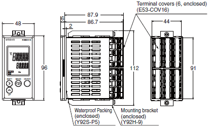
Panel Mounting Dimensions
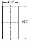
- Use M3.5 crimp terminals.
- The mounting panel must be 1 to 8 mm thick.
- When mounting KM50-E Power Monitors side by side, provide sufficient space between them.
Reference separation: 120 mm (vertical), 60 mm (horizontal)
Both of these are distances from the center of the Power Monitor. - Make sure that the rated ambient temperature of the KM50-E Power Monitor is not exceeded when more than one Power Monitor is mounted.
CT
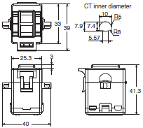
KM20-CTF-5A
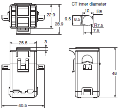
KM20-CTF-50A
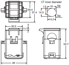
KM20-CTF-100A
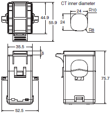
KM20-CTF-200A
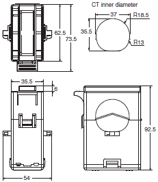
KM20-CTF-400A/600A
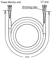
KM20-CTF-CB3 (Special CT Cable)
Special CTs and CT Cable
- Use only the CTs and CT Cable specified by OMRON.
- If any other CTs or CT Cables are used, normal measurements will not be possible.
- The Special CTs have polarity.
Connect the Special CT correctly, connecting the 1S or 3S terminal on the Power Monitor to the k terminal on the CT and the 1L or 3L terminal on the Power Monitor to the l terminal on the CT. - Do not ground the Special CTs. Failure may occur.
Special CTs for the KM20-B40 and KM20-B40-FLK
Rated primary current of 5 A: KM20-CTF-5A
Rated primary current of 50 A: KM20-CTF-50A
Rated primary current of 100 A: KM20-CTF-100A
Rated primary current of 200 A: KM20-CTF-200A
Rated primary current of 400 A: KM20-CTF-400A
Rated primary current of 600 A: KM20-CTF-600A
KM20-CTF-series CT Cable
KM20-CTF-CB3 (3 m)
Optional Accessories
Mounting Bracket
KM50-OPT-ED1
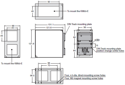
KM50-OPT-EM1
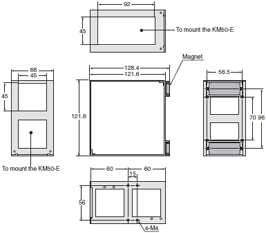
last update: December 03, 2014
OMRON KM50-E catalog
KM50-E Smart Power Monitor/Catalog- Catalog
- Manual
- CAD
English
Global Edition
| Catalog Name | Catalog Number [size] | Last Update | |
|---|---|---|---|
| | - [1955KB] | Sep 24, 201520150924 | KM50-E1-FLK Data Sheet |
OMRON KM50-E lineup
KM50-E Smart Power Monitor/Lineuplast update: December 03, 2014
KM50-E Smart Power Monitor
| Model | Applicable circuits | Power supply voltage (shared) | Dimensions | Commu- nications | Protocol |
|---|---|---|---|---|---|
| KM50-E1-FLK | Single-phase, 2-wire: 100 to 480 VAC Single-phase, 3-wire: 100/200 VAC Three-phase, 3-wire: 100 to 480 VAC Three-phase, 4-wire: 85 to 277 VAC | 100 to 240 VAC | 96 × 48 × 93 (H × W × D) | RS-485 | CompoWay/F: 31 nodes, Modbus: 99 nodes (Both are supported by the same model.) |
CTs
These CTs must be used with the KM50/KM20-B40/-FLK. Do not use them with any other products.
| Model | Rated primary current | Rated secondary current | Installation |
|---|---|---|---|
| KM20-CTF-5A | 5 A | Special output | Installed separately |
| KM20-CTF-50A | 50 A | ||
| KM20-CTF-100A | 100 A | ||
| KM20-CTF-200A | 200 A | ||
| KM20-CTF-400A | 400 A | ||
| KM20-CTF-600A | 600 A |
Note: CT Cables are not included with the CTs.
CT Cable
| Model | Cable length |
|---|---|
| KM20-CTF-CB3 | 3 m |
Note: Either use the CT Cable specified by OMRON or use 1.25-B3A crimp terminals and AWG22 wire from J.S.T. Mfg.
Co., Ltd.
Mounting Brackets (for DIN Track or Magnet Mounting)
| Model | Specification |
|---|---|
| KM50-OPT-ED1 * | DIN Track mounting |
| KM50-OPT-EM1 * | Magnet mounting |
* You can mount one KM50-E or two KM50-C Power Monitors.
last update: December 03, 2014
- NO. KM50-E
- TYPE:Electric Power Monitoring Equipment Smart Power Monitor
 Copyright Statement
 - DATE:2021-06-11
- Associated products:
KM1 Multi-circuit Smart Power Monitor/Features KM50-C Smart Power Monitor/Features