OMRON S82SPower Supplies / In Addition/ Power Supplies/Switch mode power supplies
OMRON S82S Power Supplies / In Addition
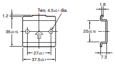
OMRON S82S Dimensions
/Images/l_789-25-119011-198x198.jpglast update: April 21, 2017
• 65 mm depth enables mounting onto control panels with 100 mm depth.
• Inputs: 10.2 to 27.6 VDC (DC input)
• 7.5-W models provide both ±12-V and ±15-V outputs.
• A complete lineup with 10 different models.
• UL and CSA approved.
• RoHS-compliant
last update: April 21, 2017
Purchase the OMRON Switch mode power supplies Please fill in the following
If you have just landed here, this product OMRON S82S Power Supplies / In Addition,Power Supplies / In Addition is offered online by Tianin FLD Technical Co.,Ltd. This is an online store providing Power Supplies / In Addition at wholesale prices for consumers. You can call us or send enquiry, we would give you the prices, packing,deliverty and more detailed information on the S82S We cooperate with DHL,TNT,FEDEX,UPS,EMS,etc.They guarantee to meet your needs in terms of time and money,even if you need your OMRON S82SPower Supplies / In Addition tomorrow morning (aka overnight or next day air) on your desk, 2, 3 days or more.Note to international customers, YES, we ship worldwide.
G3PW Single-phase Power Controller/Features
E2EQ Spatter-resistant Proximity Sensor/Features
EE-SPW321 / 421 Photomicrosensor with Amplifier and Cable/Features
NX-SI / SO Safety I/O Unit/Features
GX-JC03 / JC06 EtherCAT Junction Slave/Features
OMRON S82S catalog
S82S Switch Mode Power Supply (3/7.5-W Models)/Catalog- Catalog
- Manual
- CAD
English
Global Edition
| Catalog Name | Catalog Number [size] | Last Update | |
|---|---|---|---|
| | - [1002KB] | Apr 03, 201720170403 | S82S Data Sheet |
OMRON S82S dimension
S82S Switch Mode Power Supply (3/7.5-W Models)/Dimensionslast update: July 01, 2016
S82S-73[][] (3 W)
S82S-77[][] (7.5 W)

* A distance of 7.3 mm is required between the model and the mounting surface when the mounting bracket provided
with the model is used.
Note: If more than one Power Supply is installed in a row, keep a distance of 20 mm min. (L = 20 mm min.) between each
adjacent Power Supply.
Accessories
Mounting Bracket
Used when not mounting the Power Supply directly on the DIN Rail.

DIN Rail (Order Separately)
Mounting Rail (Material: Aluminum)
PFP-100N
PFP-50N

Note: The values shown in parentheses are for the PFP-50N.
PFP-100N2

last update: July 01, 2016
OMRON S82S lineup
S82S Switch Mode Power Supply (3/7.5-W Models)/Lineuplast update: September 24, 2012
| Power ratings | Output voltage | Output current | Model |
|---|---|---|---|
| 3 W | 5 V | 0.6 A | S82S-7305 |
| 12 V | 0.25 A | S82S-7312 | |
| 15 V | 0.2 A | S82S-7315 | |
| 24 V | 0.13 A | S82S-7324 | |
| 7.5 W | 5 V | 1.5 A | S82S-7705 |
| 12 V | 0.6 A | S82S-7712 | |
| 15 V | 0.5 A | S82S-7715 | |
| 24 V | 0.3 A | S82S-7724 | |
| ±12 V | 0.3 A (+12 V)/0.2 A (-12 V) | S82S-7727 | |
| ±15 V | 0.2 A (+15V)/0.2A (-15 V) | S82S-7728 |
last update: September 24, 2012
OMRON S82S specification
S82S Switch Mode Power Supply (3/7.5-W Models)/Specificationslast update: September 09, 2015
Ratings/Characteristics
| Item | DC input | ||||
|---|---|---|---|---|---|
| 3 W | Single output 7.5 W | Dual Output 7.5 W | |||
| Efficiency (typical) | 60% min. | 66% min. | 64% min. | ||
| Input | Voltage | AC | No | ||
| DC | 10.2 to 27.6 VDC | ||||
| Current *1 | 0.6 A max. | 1.2 A max. | |||
| Output *2 | Voltage adjustment range | ±5% *3 | None *4 | ||
| Ripple *1 | 2% (p-p) max. | ||||
| Input variation influence | 0.5% max. | ||||
| Load variation influence | 1.5% max. | +V: 1.5% max. -V: 3% max. | |||
| Temperature variation influence | 0.05%/°C max. | ||||
| Additional function | Overload protection *5 | 105% min., voltage drop, automatic reset | |||
| Other | Ambient operating temperature | Refer to the derating curve in Engineering Data | |||
| Storage temperature | -25 to 65°C | ||||
| Ambient operating humidity | 25% to 85% (storage humidity: 20% to 90%) | ||||
| Dielectric strength | 1.5 kVAC for 1 min. (between all input terminals and all output terminals/PE terminals), current off: 10 mA | ||||
| Insulation resistance | 100 MΩ min. (between all output terminals and all input terminals/PE terminals) at 500 VDC | ||||
| Vibration resistance | 10 to 55 Hz, 0.375-mm single amplitude for 2 hours each in X, Y, and Z directions | ||||
| Shock resistance | 294 m/s2, 3 times each in ±X, ±Y, ±Z directions | ||||
| Output indicator | Yes (color: green) | ||||
| Approved standards | Refer to List of Certified Models for details. | ||||
| Weight | 150 g max. | ||||
*1. A 100% load for rated input voltage.
*2. Output characteristics are measured at the power supply output terminals.
*3. If the output voltage adjuster (V.ADJ) is turned, the voltage will increase by more than 50% of the voltage adjustment
range. When adjusting the output voltage, confirm the actual output voltage from the Power Supply and be sure that
the load is not damaged.
*4. The settings for the output voltage must be within the following range:
+V: ±1% of the rated value
–V: ±5% of the rated value
*5. Refer to Overload Protection on Data Sheet for details.
last update: September 09, 2015
- NO. S82S
- TYPE:Power Supplies Switch mode power supplies
 Copyright Statement
 - DATE:2021-06-21
- Associated products:
S8TS Switch Mode Power Supply/Features S8VK-C Switch Mode Power Supply (60/120/240/480-W Models)/Features