
OMRON OS32CSafety Components/ Safety Laser Scanners/ Copyright Statement
OMRON OS32C Safety Components
OMRON OS32C Dimensions
/Images/l_2717-25-119001-198x198.jpglast update: January 7, 2019
Operating state can be determined at a glance
Eight sector indicators* show the direction of intrusion.
Front display shows operating state and error codes.
* US patent No. for individual sector indicators: US 6,753,776 B2

Integrated management via Ethernet
Industry's first Ethernet-compliant Safety Laser Scanner allows the user to check operating state and analyze the cause of an emergency stop via LAN even in large-scale applications using multiple scanners.
* Multiple OS32Cs cannot be monitored simultaneously.

Setting 70 combinations
For complex AGV applications, up to 70 combinations - each with one safety zone and two warning zones - can be set. The two warning zones can be set to support various purposes such as warning sound and speed control.

Simplified Wiring
OMRON STI's innovative I/O method requires fewer inputs when configuring multiple zones. Only 4 inputs are required to select from 6 zone sets.
If all 8 inputs are used, up to 70 zone sets are available.


Reducing Erroneous Detections in Safety Zone
PTM (Pollution Tolerance Mode) enables a filter that allows the OS32C to distinguish between more than one detected reflection pulses. Ignoring small reflection pulses which could be caused by airborne dust or other contaminants in the safety zone.
This function prevents nuisance machine stops due to dust.

New convenient and easy-to-use functions
Replacable sensor, no reprogramming needed
No reprogramming needed, the configuration is stored in the I/O block. Replacing a damaged sensor is fast and easy.

Reference Boundary Monitoring function
The OS32C constantly monitors reference points and turns OFF the safety outputs when a shift in its position is detected.
(Per international standard IEC 61496-3, area scanners used in applications where the angle of approach exceeds +/- 30 degrees with respect to the detection plane, must use RBM in the detection zone.)

Cable Access Options
To tailor the OS32C to your installation, two options are available for the location of the power and ethernet connections:
OS32C-BP(-4M)/OS32C-BP-DM(-4M) (Cable access from the back)OS32C-SP1(-4M)/OS32C-SP1-DM(-4M) (Cable access from the left side)These can be selected according to the needs of AGV or facilities design.

Easy configuration of complex zones
The configuration of the safety zone and warning zones can be done in real time using a PC. Configurations can also be created or modified offline.

EtherNet/IPTM for Status and Measurement Data
The OS32C system status, zone status, and measurement data can all be monitored over EtherNet/IP.

EtherNet/IP™ is the trademarks of ODVA.
Windows is registered trademarks of Microsoft Corporation in the USA and other countries.
Other company names and product names in this document are the trademarks or registered trademarks of their respective companies.
Microsoft product screen shot(s) reprinted with permission from Microsoft Corporation.
last update: January 7, 2019
Purchase the OMRON  Copyright Statement Please fill in the following
If you have just landed here, this product OMRON OS32C Safety Components,Safety Components is offered online by Tianin FLD Technical Co.,Ltd. This is an online store providing Safety Components at wholesale prices for consumers. You can call us or send enquiry, we would give you the prices, packing,deliverty and more detailed information on the OS32C We cooperate with DHL,TNT,FEDEX,UPS,EMS,etc.They guarantee to meet your needs in terms of time and money,even if you need your OMRON OS32CSafety Components tomorrow morning (aka overnight or next day air) on your desk, 2, 3 days or more.Note to international customers, YES, we ship worldwide.
F3W-D Picking Sensor/Features
E5CS Temperature Controllers/Features
H5F Digital Daily Time Switch/Features
NX-ECS[][][] NX-series SSI Input Unit/Features
WS02-CFDC1, 3G8E2-DRM21-V1 DeviceNet Configurator/Features
OMRON OS32C lineup
OS32C Safety Laser Scanner/Lineuplast update: March 1, 2018
OS32C (Power cable is sold separately.)
| Appearance | Description | Max. Operating Range (Safety Zone) | Model | Remarks |
|---|---|---|---|---|
 | OS32C with back location cable entry | 3m | OS32C-BP VER2 | CD-ROM (Configuration tool) OS supported: Windows XP (32-bit version, Service Pack 3 or later) Windows 7 (32-bit version/ 64-bit version), Windows 8.1 (32-bit version/ 64-bit version), Windows 10 (32-bit version/ 64-bit version) For configuration tool version, refer to Catalog. |
| 4m | OS32C-BP-4M | |||
 | OS32C with side location cable entry * | 3m | OS32C-SP1 VER2 | |
| 4m | OS32C-SP1-4M | |||
 | OS32C with EtherNet/IP and back location cable entry | 3m | OS32C-BP-DM | |
| 4m | OS32C-BP-DM-4M | |||
 | OS32C with EtherNet/IP and side location cable entry * | 3m | OS32C-SP1-DM | |
| 4m | OS32C-SP1-DM-4M |
* For OS32C-SP1(-DM), each connector is located on the left as viewed from the back of the I/O block.
Power Cable
| Appearance | Description | Model | Remarks |
|---|---|---|---|
 | Cable length: 3 m | OS32C-CBL-03M | One cable is required per sensor. |
| Cable length: 10 m | OS32C-CBL-10M | ||
| Cable length: 20 m | OS32C-CBL-20M | ||
| Cable length: 30 m | OS32C-CBL-30M |
Ethernet Cable
| Appearance | Description | Model | Remarks |
|---|---|---|---|
 | Cable length: 2 m | OS32C-ECBL-02M | Required for configuration and monitoring. |
| Cable length: 5 m | OS32C-ECBL-05M | ||
| Cable length: 15 m | OS32C-ECBL-15M |
Note: An ethernet cable with an M12, 4-pin connector is required.
Mounting Brackets
| Appearance | Description | Model | Remarks |
|---|---|---|---|
 | Bottom/side mounting bracket | OS32C-BKT1 | Bottom/side mounting bracket x 1, unit mounting screws x 4 sets |
 | XY axis rotation mounting bracket | OS32C-BKT2 | XY axis rotation mounting bracket x 1, unit mounting screws x 6 sets, bracket mounting screws x 1 set (must be used with OS32C-BKT1) |
 | Simple mounting bracket | OS32C-BKT3 | Simple mounting brackets x 2, unit mounting screws x 4 sets * |
 | Protective cover for window | OS32C-BKT4 | |
 | Mounting stand | OS32C-MT | When using a mounting stand, use an OS32C with side location cable entry (OS32C-SP1(-DM)). The OS32C with back location cable entry (OS32C-BP(-DM)) cannot be mounted. Use with mounting brackets (OS32C-BKT1 and OS32C-BKT2). |
 | Hardware kit for mounting stand | OS32C-HDT | Mounting screws x 3 sets Use this when mounting a bracket to the mounting stand. |
* There are eight OS32C mounting screws: four screws for singular use, and four screws for protective cover for window.
Accessories
| Appearance | Description | Model | Remarks | |
|---|---|---|---|---|
 | Scan window | OS32C-WIN-KT | Spare for replacement | |
 | Sensor block without I/O block Max. Operating Range: 3 m | OS32C-SN * | Spare for replacement | |
| Sensor block without I/O block Max. Operating Range: 4 m | OS32C-SN-4M | |||
 | Sensor block without I/O block for EtherNet/IP Max. Operating Range: 3 m | OS32C-SN-DM | Spare replacement for EtherNet/IP | |
| Sensor block without I/O block for EtherNet/IP Max. Operating Range: 4 m | OS32C-SN-DM-4M | |||
 | I/O block | With cable access from the back | OS32C-CBBP | Spare for replacement |
 | With cable access from the left side | OS32C-CBSP1 | Spare for replacement | |
* When ordering, add “VER2” to the end of the model number. (OS32C-SN VER2)
last update: March 1, 2018
OMRON OS32C specification
OS32C Safety Laser Scanner/Specificationslast update: March 1, 2019
Rating/Performance
| Sensor Type | Type 3 Safety Laser Scanner | |
|---|---|---|
| Performance Level (PL)/ Safety Category | PLd/Safety Category 3 (ISO 13849-1) | |
| Functional Safety of Electrical/ Electronic/Programmable Electronic Safety-related Systems | SIL 2, PFHD = 8.3 × 10⁻⁸(IEC61508) | |
| Detection Capability | Configurable; Non-transparent with a diameter of 30, 40, 50, 70mm (1.8% reflectivity or greater) (default: 70 mm) | |
| Monitoring Zone | Monitoring Zone Set Count: (Safety Zone + 2 Warning Zones) x 70 sets | |
| Operating Range | OS32C-[][][] | Safety Zone: 1.75 m (min. obj. resolution of 30 mm) 2.5 m (min. obj. resolution of 40 mm) 3.0 m (min. obj. resolution of 50 mm or 70 mm) Warning Zone: 10.0 m |
| OS32C-[][][]-4M | Safety Zone: 1.75 m (min. object resolution of 30mm) 2.5 m (min. object resolution of 40 mm) 3.0 m (min. object resolution of 50 mm) 4.0 m (min. object resolution of 70 mm) Warning Zone: 15.0 m | |
| Maximum Measurement Error | 100 mm (at range of 3 m or less) *1 110 mm (at distance greater than 3 m and up to 4m) *1 | |
| Detection Angle | 270° | |
| Angular Resolution | 0.4° | |
| Laser Beam Diameter | 6 mm at optics cover, 14 mm (typical) at 3 m. | |
| Laser Scan Plane Height | 67mm from the bottom of the scanner (see "External Dimensional Drawings" on Catalog for more detail.) | |
| Response Time | Response time from ON to OFF: From 80 ms (2 scans) to 680 ms (up to 17 scans) *8 Response time from OFF to ON: Response time from ON to OFF + 100 ms to 60 s (Configurable) | |
| Zone Switching Time | 20 to 320 ms | |
| Line Voltage | 24 VDC +25%/-30% (ripple p-p 2.5 V max.) *2 | |
| Power Consumption | Normal operation: 5 W max., 4 W typical (without output load) *3 Standby mode: 3.75 W (without output load) | |
| Emission Source (Wavelength) | Infrared Laser Diode (905 nm) | |
| Laser Protection Class | Class 1: IEC/EN60825-1 Class 1: JIS C 6802 Class I: CFR21 1040.10, 1040.11 | |
| Safety Output (OSSD) | PNP transistor x 2, load current of 250 mA max., residual voltage of 2 V max., load capacity of 2.2 μF max., leak current of 1 mA max. *3, *4, *5 | |
| Auxiliary Output (Non-Safety) | NPN/PNP transistor x 1, load current of 100 mA max., residual voltage of 2 V max., leak current of 1 mA max. *4, *5, *7 | |
| Warning Output (Non-Safety) | NPN/PNP transistor x 1, load current of 100 mA max., residual voltage of 2 V max., leak current of 1 mA max. *4, *5, *7 | |
| Operation Mode | Auto Start, Start Interlock, Start/Restart Interlock | |
| Input | External Device Monitoring (EDM) | ON: 0 V short (input current of 50 mA), OFF: Open |
| Start | ON: 0 V short (input current of 20 mA), OFF: Open | |
| Zone Select | ON: 24 V short (input current of 5 mA), OFF: Open | |
| Stand-by | ON: 24 V short (input current of 5 mA max.), OFF: Open | |
| Connection Type | Power Cable: 18-pin mini-connector (pigtail) Communication Cable: M12, 4-pin connector | |
| Connection with PC | Communication: Ethernet *6 OS Supported:Windows XP (32-bit version, Service Pack 3 or later), Windows 7 (32-bit version/64-bit version), Windows 8.1 (32-bit version/64-bit version), Windows 10 (32-bit version/64-bit version) | |
| Indicators | RUN indicator: Green, STOP indicator: Red, Interlock Indicator: Yellow, Warning Output Indicator: Orange Status/Diagnostic Display: 2 x 7-segment LEDs, Individual Sector Indicators: Red LED x 8 | |
| Protective Circuit | Protection against output load short and reverse power connection | |
| Ambient Temperature | Operation: -10 to 50 °C, Storage: -25 to 70 °C | |
| Ambient Humidity | Operation & Storage: 95% RH max., non-condensing | |
| Ambient Operation Illumination | Incandescent lamp: Illumination on receiving surface 1500 lx max. (an angle of laser scanning plane and disturbance light must be +/-5 degrees or more) | |
| Insulation Resistance | 20 MΩ or higher (500 VDC) | |
| Dielectric Withstand Voltage | 350VDC, 1 minute | |
| Enclosure Rating | IP65 (IEC60529) | |
| Enclosure | Sensor head: Die-cast aluminum, optical cover: Polycarbonate, I/O block: Die-cast aluminum | |
| Dimensions (WxHxD) | 133.0 x 104.5 x 142.7 mm (except cable) | |
| Impact Resistance | 98 m/s2 1,000 times for each of X, Y, and Z directions (IEC60068-2-29) | |
| Vibration | 10 to 55 Hz double-amplitude of 0.7 mm, 20 sweepings for X, Y, and Z directions (IEC60068-2-6) | |
| Weight (Main Unit only) | 1.3 kg | |
| Power Cable | Up to 30 m | |
| Communication Cable | Up to 100 m for 100BASE-TX cable *9 | |
| Approvals | Certificated by: TÜV Rheinland, UL Standards: EN61496-1 (Type 3 ESPE), EN61496-3 (Type 3 AOPDDR), EN61508 (SIL2), IEC61496-1 (Type 3 ESPE), IEC61496-3 (Type 3 AOPDDR), IEC61508 (SIL2), UL508, UL1998, CAN/CSA-C22.2 No. 14, CAN/CSA-C22.2 No. 0.8 | |
*1. An additional measurement error may need to be added due to reflective backgrounds.
*2. For power source specification, refer to “Safety Precautions” on Catalog.
*3. Rated current of OS32C is 1.025 A max. (OS32C 210 mA + OSSD A load + OSSD B load + Auxiliary output load +
Warning output load + Functional Inputs).
Where functional inputs are: EDM input ... 50 mA Start input ... 20 mA Standby input ... 5 mA Zone X input ... 5 mA x 8
(eight zone set select inputs)
*4. Output voltage is Input voltage - 2.0 VDC.
*5. Total consumption current of 2 OSSDs, auxiliary output, and warning output must not exceed 700 mA.
*6. An ethernet cable with an M12, 4-pin connector is required.
*7. Output polarity (NPN/PNP) is configurable via the configuration tool.
*8. Pollution Tolerance mode will add 6 ms to each scan time.
*9. Omron only supplies up to a 15 m Ethernet cable. For longer lengths a connection to a network switch/router is needed.
last update: March 1, 2019
OMRON OS32C dimension
OS32C Safety Laser Scanner/Dimensionslast update: September 15, 2016
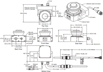
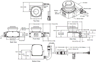
(Unit: mm)
OS32C with Back Location Cable Entry/with EtherNet/IP and Back Location Cable Entry
OS32C-BP
OS32C-BP-DM
OS32C-BP-4M
OS32C-BP-DM-4M
OS32C with Side Location Cable Entry/with EtherNet/IP and Side Location Cable Entry
OS32C-SP1
OS32C-SP1-DM
OS32C-SP1-4M
OS32C-SP1-DM-4M
OS32C with Top Guard Kit
OS32C-BP/OS32C-BP-DM/OS32C-BP-4M/OS32C-BP-DM-4M + OS32C-BKT4
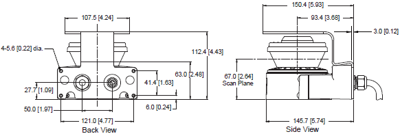
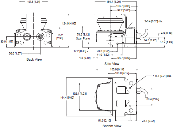
OS32C with Bottom/Side Mounting Brackets
OS32C-BP/OS32C-BP-DM/OS32C-BP-4M/OS32C-BP-DM-4M + OS32C-BKT1
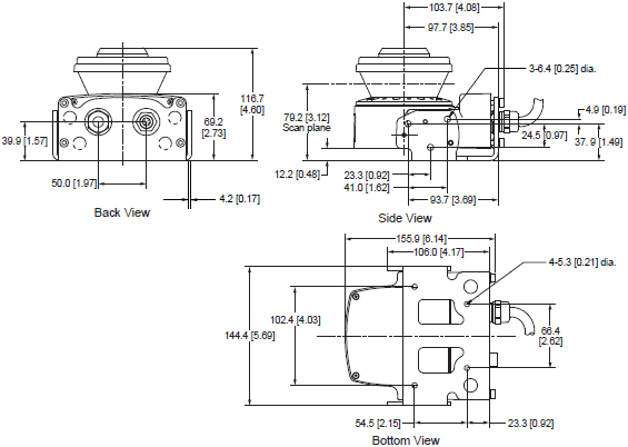
OS32C with Simple Mounting Bracket
OS32C-BP/OS32C-BP-DM/OS32C-BP-4M/OS32C-BP-DM-4M + OS32C-BKT3
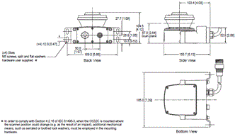
OS32C with Bottom/Side Mounting Brackets and Top Guard Kit
OS32C-BP/OS32C-BP-DM/OS32C-BP-4M/OS32C-BP-DM-4M + OS32C-BKT1 + OS32C-BKT4
OS32C with Bottom/Side Mounting Brackets and XY Axis Rotation Mounting Kit
OS32C-BP/OS32C-BP-DM/OS32C-BP-4M/OS32C-BP-DM-4M + OS32C-BKT1 + OS32C-BKT2
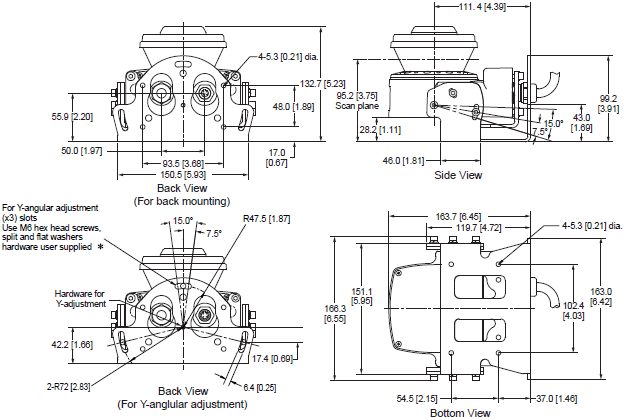
* In order to comply with Section 4.2.16 of IEC 61496-3, when the OS32C is mounted where the scanner position could
change (e.g. as the result of an impact), additional mechanical means, such as serrated or toothed lock washers,
must be employed in the mounting hardware.
OS32C with Bottom/Side Mounting Brackets, XY Axis Rotation Mounting Kit and Top Guard Kit
OS32C-BP/OS32C-BP-DM/OS32C-BP-4M/OS32C-BP-DM-4M + OS32C-BKT1 + OC32C-BKT2 + OS32C-BKT4
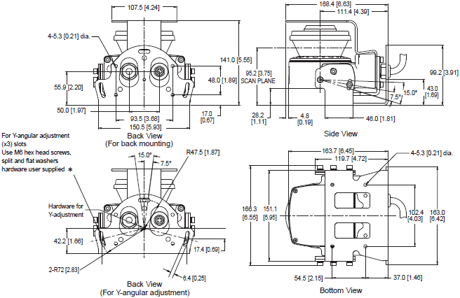
* In order to comply with Section 4.2.16 of IEC 61496-3, when the OS32C is mounted where the scanner position could
change (e.g. as the result of an impact), additional mechanical means, such as serrated or toothed lock washers,
must be employed in the mounting hardware.
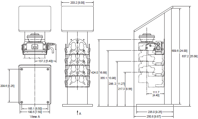
OS32C with Bottom/Side Mounting Brackets, XY Axis Rotation Mounting Kit, Mounting Stand and Mounting Stand Hardware Kit
OS32C-SP1/OS32C-SP1-DM/OS32C-BP-4M/OS32C-BP-DM-4M + OS32C-BKT1 + OS32C-BKT2 + OS32C-MT + OS32C-HDT
Power Cable
OS32C-CBL-[][]M

Ethernet Cable
OS32C-ECBL-[][]M

last update: September 15, 2016
OMRON OS32C catalog
OS32C Safety Laser Scanner/Catalog- Catalog
- Manual
- CAD
English
Global Edition
| Catalog Name | Catalog Number [size] | Last Update | |
|---|---|---|---|
| | Z298-E1-04 [7062KB] | Mar 01, 201920190301 | OS32 Catalog |
- NO. OS32C
- TYPE:Safety Laser Scanners
 Copyright Statement
  Copyright Statement
 - DATE:2021-06-08
- Associated products:
E3ZS, E3FS Single-beam Safety Sensor/Features D4N Safety Limit Switch/Features