OMRON XSwitches/ Basic Switches/Basic Switches (Z-Size)
OMRON X Switches
OMRON X Dimensions
/Images/l_291-25-119058-198x198.jpglast update: December 19, 2013
• Incorporates a small permanent magnet in the contact mechanism to deflect the arc to effectively extinguish it.
• Same shape and mounting procedures as the Z Basic Switches.
last update: December 19, 2013
Purchase the OMRON Basic Switches (Z-Size) Please fill in the following
If you have just landed here, this product OMRON X Switches,Switches is offered online by Tianin FLD Technical Co.,Ltd. This is an online store providing Switches at wholesale prices for consumers. You can call us or send enquiry, we would give you the prices, packing,deliverty and more detailed information on the X We cooperate with DHL,TNT,FEDEX,UPS,EMS,etc.They guarantee to meet your needs in terms of time and money,even if you need your OMRON XSwitches tomorrow morning (aka overnight or next day air) on your desk, 2, 3 days or more.Note to international customers, YES, we ship worldwide.
E3X-DRT21-S VER.3 Fiber Amplifier Sensor Communication Unit/Features
3Z4S-LE SV-V Series Lens for C-mount Cameras/Features
H7CX-A Multifunction Preset Counter/Features
3G8F7-DRM21-E DeviceNet Board (PCI Board)/Features
GT1-ROS16 / ROP08 / FOP08 Relay Output Units/Features
OMRON X dimension
X General-purpose Basic Switch/Dimensionslast update: December 18, 2015
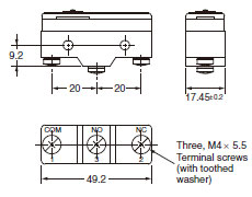
Terminals
Screw Terminals (-B)
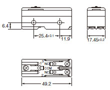
Solder Terminal (-A)
("-A" is not included in the model numbers.)
Note: 1. Tighten the terminal screws to a torque of 0.78 to 1.18 Nm.
2. Unless otherwise specified, a tolerance of ±0.4 mm applies to all dimensions.
3. In case of DC voltage, set the COM to the positive terminal.
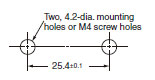
Mounting
Use M4 mounting screws with plane washers or spring washers to securely mount the Switch. Tighten the screws to a torque of 1.18 to 1.47 Nm.
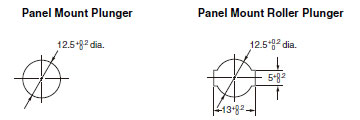
The Switch can be panel mounted, provided that the hexagonal nut of the actuator is tightened to a torque of 2.94 to 4.9 Nm.
The models, illustrations, and graphics are for screw-terminal models. (The dimensions for models that are omitted here are the same as for pin-plunger models.)
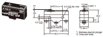
Pin Plunger
X-10G-B
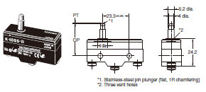
Slim Spring Plunger
X-10GS-B
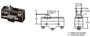
Short Spring Plunger
X-10GD-B
Panel Mount Plunger
X-10GQ-B
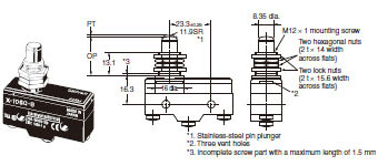
Note: Do not use both the M12 mounting screw and the mounting holes in the case at the same time. Doing so will cause
stress to be applied to the Switch, possibly damaging the case or cover.
Panel Mount Roller Plunger
X-10GQ22-B
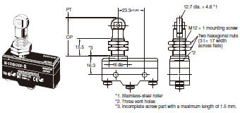
Note: Do not use both the M12 mounting screw and the mounting holes in the case at the same time. Doing so will cause
stress to be applied to the Switch, possibly damaging the case or cover.
Panel Mount Cross Roller Plunger
X-10GQ21-B
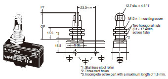
Note: Do not use both the M12 mounting screw and the mounting holes in the case at the same time. Doing so will cause
stress to be applied to the Switch, possibly damaging the case or cover.
Leaf Spring
X-10GL-B
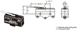
Note: Unless otherwise specified, a tolerance of ±0.4 mm applies to all dimensions.
* Be sure to use the switch at the rated OT value of 1.6 mm.
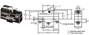
Short Hinge Lever
X-10GW21-B
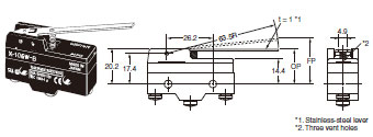
Hinge Lever
X-10GW-B
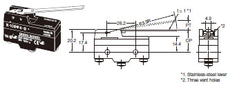
Low-force Hinge Lever
X-10GW4-B
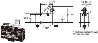
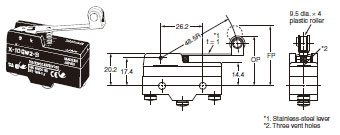
Short Hinge Roller Lever
X-10GW22-B
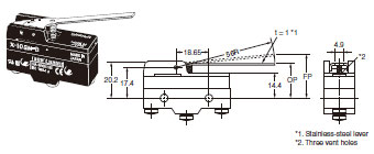
Hinge Roller Lever
X-10GW2-B
Reverse Hinge Lever
X-10GM-B
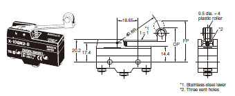
Reverse Short Hinge Lever
X-10GM22-B
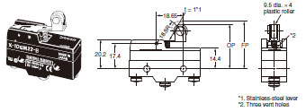
Reverse Hinge Roller Lever
X-10GM2-B
Note: Unless otherwise specified, a tolerance of ±0.4 mm applies to all dimensions.
Terminal Covers
AP-A
Soldering Terminal Use (Phenol Resin)
Note: The Cover has five thin, easy-to-separate portions for easy lead wire connections.
AP-B
Screw Terminal Use (Phenol Resin)
Note: The Cover has six thin, easy-to-separate portions for easy lead wire connections.
AP1-A
Soldering Terminal Use (Metal Press Mold)
Note: The Cover has five holes for easy lead wire connections.
AP1-B
Screw Terminal Use (Metal Press Mold)
Note: The Cover has six holes for easy lead wire connections.
AP-Z
Soldering or Screw Terminal Use (Vinyl Chloride)
Note: Each dimension has a tolerance of ±0.4 mm unless otherwise specified. (±0.8 mm for the AP-Z)
Separator
SEPARATOR FOR Z
Note: 1. Each dimension has a tolerance of ±0.4 mm unless otherwise specified.
2. The material is EAVTC (Epoxide Alkyd Varnished Tetron Cloth) and its heat-resisting temperature is 130°C.
Actuators
Hinge Lever
XAA-1
Hinge Roller Lever
ZAA-2
Short Panel Mount Plunger
ZAQ-3
Medium Panel Mount Plunger
ZAQ-2
Long Panel Mount Plunger
ZAQ-1
Panel Mount Roller Plunger
ZAQ-22
Note: Each dimension has a tolerance of ±0.4 mm unless otherwise specified.
last update: December 18, 2015
OMRON X specification
X General-purpose Basic Switch/Specificationslast update: September 24, 2012
Ratings
| Rated voltage | Non-inductive load (A) | Inductive load (A) | ||||||
|---|---|---|---|---|---|---|---|---|
| Resistive load | Lamp load | Inductive load | Motor load | |||||
| NC | NO | NC | NO | NC | NO | NC | NO | |
| 8 VDC 14 VDC 30 VDC 125 VDC 250 VDC | 10 10 10 10 3 | 3 3 3 3 1.5 | 1.5 1.5 1.5 1.5 0.75 | 10 10 10 7.5 2 | 10 10 10 6 1.5 | 5 5 5 5 2 | 2.5 2.5 2.5 2.5 1.5 | |
Note:Note:
1. The above values are for the steady-state current.
2. Inductive load has a power factor of 0.4 min. (AC) and a time constant of 7 ms max. (DC).
3. Lamp load has an inrush current of 10 times the steady-state current.
4. Motor load has an inrush current of 6 times the steady-state current.
5. The above electrical ratings also apply to the AC voltage.
6. With the reverse-type models (X-10GM[]), the normally closed circuits and normally open circuits are reversed.
7. The ratings values apply under the following test conditions:
(1) Ambient temperature: 20±2℃
(2) Ambient humidity: 65±5%RH
(3) Operating frequency: 20 operations/min
Contact Specification
| Contacts | Material | Silver |
|---|---|---|
| Gap (standard value) | 0.9 mm | |
| Inrush current | NC | 30 A max. |
| NO | 15 A max. |
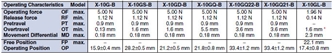
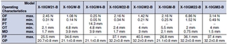
Characteristics
| Operating speed | 0.1 mm to 1 m/s *1 | |
|---|---|---|
| Operating frequency | Mechanical | 240 operations/min |
| Electrical | 20 operations/min | |
| Insulation resistance | 100 M Ω min. (at 500 VDC) | |
| Contact resistance | 15 m Ω max. (initial value) | |
| Dielectric strength | 1,500 VAC, 50/60 Hz for 1 min between terminals of the same polarity, between current-carrying metal parts and the ground, and between each terminal and non-current-carrying metal parts | |
| Vibration resistance | Malfunction | 10 to 55 Hz, 1.5-mm double amplitude *2 |
| Shock resistance | Destruction | 1,000 m/s2 max. |
| Malfunction | 300 m/s2 max. *1 *2 | |
| Durability | Mechanical | 1,000,000 operations min. |
| Electrical | 100,000 operations min. | |
| Degree of protection | IP00 | |
| Degree of protection against electric shock | Class I | |
| Proof tracking index (PTI) | 175 | |
| Ambient operating temperature | − 25 ° C to 80 ° C (with no icing) | |
| Ambient operating humidity | 35% to 85%RH | |
| Weight | Approx. 27 to 63 g | |
Note:*1. The values are for the pin plunger models. (Contact your OMRON representative for other models.)
*2. Malfunction: 1 ms max.
last update: September 24, 2012
OMRON X catalog
X General-purpose Basic Switch/Catalog- Catalog
- CAD
English
Global Edition
| Catalog Name | Catalog Number [size] | Last Update | |
|---|---|---|---|
| | - [1961KB] | Apr 01, 201620160401 | X Data Sheet |
OMRON X lineup
X General-purpose Basic Switch/Lineuplast update: December 18, 2015
| Terminal | Solder terminal  | Screw terminal  | |
|---|---|---|---|
| Actuator | Model | Model | |
| Pin plunger |  | X-10G | X-10G-B |
| Slim spring plunger |  | X-10GS | X-10GS-B |
| Short spring plunger |  | X-10GD | X-10GD-B |
| Panel mount plunger |  | X-10GQ | X-10GQ-B |
| Panel mount roller plunger |  | X-10GQ22 | X-10GQ22-B |
| Panel mount cross roller plunger |  | X-10GQ21 | X-10GQ21-B |
| Leaf spring |  | X-10GL | X-10GL-B |
| Short hinge lever |  | X-10GW21 | X-10GW21-B |
| Hinge lever |  | X-10GW | X-10GW-B |
| Low-force hinge lever |  | X-10GW4 | X-10GW4-B |
| Short hinge roller lever |  | X-10GW22 | X-10GW22-B |
| Hinge roller lever B |  | X-10GW2 | X-10GW2-B |
| Reverse hinge lever |  | X-10GM | X-10GM-B |
| Reverse short hinge roller lever * |  | X-10GM22 | X-10GM22-B |
| Reverse hinge roller lever * |  | X-10GM2 | X-10GM2-B |
* The plungers of reverse-type models are continuously pressed by the compression coil springs and the plungers are
freed by operating the levers.
Accessories (Order Separately)
Terminal Covers (Sold Separately)
The Terminal Covers can be attached to Z, A, X, and DZ Switches.
The Terminal Cover is secured with mounting screws and protects the casing and terminal wires from dust, vibration, or fingers, thus preventing terminal short-circuiting, ground faults, wire disconnection or improper connection, and electric shock accidents.
Terminal Covers made of phenol resin have five or six thin wall sections. These sections can be torn open for providing holes for lead cables at desired points.
A terminal cover can’t be used in the case of using an actuator sold separately.
| Application | Soldering terminal use | Screw terminal use | Remarks | |
|---|---|---|---|---|
| Material | Mounting direction | Model | ||
| Phenol resin | Side mounting | AP-A | AP-B | --- |
| Metal press mold | Side mounting | AP1-A | AP1-B | Used for AP-A and AP-B |
| Vinyl chloride | Side mounting | AP-Z | --- | |
Note: Use a Terminal Cover for screw terminals fir DZ-series Switches with soldering terminals.
Separator (Sold Separately)
Use a Separator when it is difficult to provide a sufficient insulation distance or when using the Switch near metal parts or copper wires.
| Model |
|---|
| SEPARATOR FOR Z |
Actuators (Sold Separately)
A Switch can be actuated by a cam or an appropriate object, in which case, use one of the following Actuators according to the application.
| Actuator | Common to Z and X models | ||
|---|---|---|---|
| Hinge lever |  | XAA-1 | |
| Hinge roller lever |  | ZAA-2 | |
| Panel mount plunger |  | Short | ZAQ-3 |
| Medium | ZAQ-2 | ||
| Long | ZAQ-1 | ||
| Panel mount roller plunger |  | ZAQ-22 | |
last update: December 18, 2015
- NO. X
- TYPE:Basic Switches Basic Switches (Z-Size)
 Copyright Statement
 - DATE:2021-06-18
- Associated products:
A General-purpose Basic Switch/Features DZ Special-purpose Basic Switch/Features