OMRON D6FZ-FGS SeriesEnergy Conservation Support / Environment Measure Equipment/ EQUO Environment Sensor/Air Flow Sensor
OMRON D6FZ-FGS Series Energy Conservation Support / Environment Measure Equipment
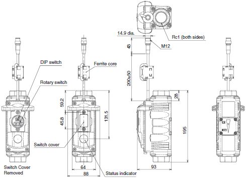
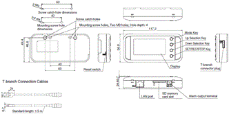
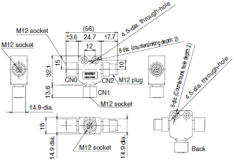
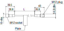
OMRON D6FZ-FGS Series Dimensions
/Images/l_3160-25-161035-198x198.jpglast update: December 03, 2014
Multi-sensing
Simultaneous Measurement of Flow, Pressure, Leakage, and Temperature
The Sensor provides multiple sensing functions.
You can identify compressed air conditions with just one Sensor.

Simple Setup
Mountable to Curved Pipes or Couplers [Silencer]
The built-in silencer eliminates ultrasonic noise and turbulence. It eliminates the need for straight pipes to make installation work easy.

High Accuracy
Highly Accurate Flow Measurements
High measuring accuracy of ±2% R.S. (at 50 L/min or less) is achieved.

Flow Measurements over a Wide Range
A wide measurement range of 1 to 1,000 L/min is achieved.
Resists Oils and Mist [Ultrasonic sensor]
A built-in ultrasonic sensor is used for flow measurements.
With high resistance to rusty pipes and oil flooded compressors, you can install the Sensor almost anywhere.
Main Features
- Two analog outputs
- Two pulse outputs
- RS-485 communications
- IP64
- Operation indicator
- Threshold values (peak, bottom, and leak)
- Alarm hold
Feature Comparison

last update: December 03, 2014
Purchase the OMRON Air Flow Sensor Please fill in the following
If you have just landed here, this product OMRON D6FZ-FGS Series Energy Conservation Support / Environment Measure Equipment,Energy Conservation Support / Environment Measure Equipment is offered online by Tianin FLD Technical Co.,Ltd. This is an online store providing Energy Conservation Support / Environment Measure Equipment at wholesale prices for consumers. You can call us or send enquiry, we would give you the prices, packing,deliverty and more detailed information on the D6FZ-FGS Series We cooperate with DHL,TNT,FEDEX,UPS,EMS,etc.They guarantee to meet your needs in terms of time and money,even if you need your OMRON D6FZ-FGS SeriesEnergy Conservation Support / Environment Measure Equipment tomorrow morning (aka overnight or next day air) on your desk, 2, 3 days or more.Note to international customers, YES, we ship worldwide.
E3X-DRT21 / SRT21 / CIF11 Communications Units for E3X-DA-N-series Fiber Amplifiers/Features
D4A-[]N General-purpose Limit Switch/Features
D4SL-N, D4SL-NSK10-LK[] Guard Lock Safety-door Switch/D4SL-N-mounting Slide Key/Features
ES1-N Infrared Thermosensor/Features
CP1W-EIP61 EtherNet/IP Communication Module for CP1L/CP1H PLCs/Features
OMRON D6FZ-FGS Series lineup
D6FZ-FGS Series Air Flow Sensor/Lineuplast update: December 03, 2014
Units
| Appearance | Product name | Model |
|---|---|---|
 | 1000L-type Air Flow Sensor (cable length: 0.2 m) | D6FZ-FGS1000 |
 | Air Flow Station (cable length: 1.5 m, including T-branch Connector cable) | D6FZ-FGX21 |
 | 1000L-type Air Flow Sensor Set • 1000L-type Air Flow Sensor • Air Flow Station • T-branch Connector • Cable with Connector on One End (3 m) | D6FZ-FGS1000-S |
Option (sold separately)
| Appearance | Product name | Model | ||
|---|---|---|---|---|
 | T-branch Connector | D6FZ-FC02 | ||
 | (D6FZ-FGX21 Air Flow Station only) Mounting magnets * • Mounting magnets: 2 • Phillips screws (M3): 2 | ZN9-EM01-S | ||
 | Cable with Connector on One End | Cable length: 3 m | M12 connector (8-pin) | D6FZ-JD3A |
| Cable length: 10 m | D6FZ-JD10A | |||
| Cable length: 20 m | D6FZ-JD20A | |||
 | Cable with Connectors on Both Ends | Cable length: 3 m | M12 connector (8-pin) | D6FZ-JD3B |
| Cable length: 5 m | D6FZ-JD5B | |||
| Cable length: 10 m | D6FZ-JD10B | |||
| Cable length: 20 m | D6FZ-JD20B | |||
* When magnets are used, the maximum vibration resistance is 55 Hz.
last update: December 03, 2014
OMRON D6FZ-FGS Series dimension
D6FZ-FGS Series Air Flow Sensor/Dimensionslast update: December 03, 2014
Unspecified dimensions tolerances: Tolerance class IT16
Air Flow Sensor
D6FZ-FGS1000

Air Flow Station
D6FZ-FGX21

T-branch connector
D6FZ-FC02

Cables with Connector on One End
D6FZ-JD3A (L = 3 m)
D6FZ-JD10A (L = 10 m)
D6FZ-JD20A (L = 20 m)

Cables with Connectors on Both Ends
D6FZ-JD3B (L = 3 m)
D6FZ-JD5B (L = 5 m)
D6FZ-JD10B (L = 10 m)
D6FZ-JD20B (L = 20 m)

last update: December 03, 2014
OMRON D6FZ-FGS Series specification
D6FZ-FGS Series Air Flow Sensor/Specificationslast update: December 01, 2016
Ratings
Air Flow Sensor
| Model | D6FZ-FGS1000 | ||
|---|---|---|---|
| Applicable fluid | Air or nitrogen (N2) | ||
| Working pressure | 0.99MPa max. | ||
| Meas- urement | Flow *1 | Detection range | 1 to 1,000 L/min (std) |
| Resolution | 0.1 L/min | ||
| Accuracy | ±2.0% of reading at 50 L/min (std) or higher *2 | ||
| ±0.1% F.S. at less than 50 L/min *2 | |||
| Pressure | Detection range | 0 to 0.99 MPa | |
| Accuracy | 2% F.S. | ||
| Temper- ature | Detection range | -10 to 60°C | |
| Accuracy | ±1.5% (absolute temperature) | ||
| Resist- ance to envi- ronment | Operating temperature | -10 to 60°C (with no condensation or icing) | |
| Operating humidity | 35% to 85% RH (with no condensation or icing) | ||
| Vibration resistance (destruction) | 10 to 55 Hz with a 0.7-mm double amplitude or acceleration of 50 m/s2 for 80 min each in X, Y, and Z directions | ||
| Shock resistance (destruction) | 150 m/s2 3 times each in six directions (up/down, left/right, forward/backward) | ||
| Pressure loss | Direct piping: 10 kPa max. (0.5 MPa, at maximum flow) Using Coupler (TL model from Nagahori Industry Co., Ltd.): 10 kPa max. (0.5 MPa, at maximum flow) | ||
| Power supply voltage | For one Sensor: 16 to 24 VDC ±10%, ripple (p-p): 10% max., For multiple Sensors: 24 VDC ±10%, ripple (p-p): 10% max. *3 | ||
| Power consumption | 2 W max. | ||
| Measurement cycle | Approx. 62.5 ms | ||
| Display | Display method | Status display with 2-color LED (lit or flashing) | |
| Displayed contents | Presence of power, air flow, and error alarm | ||
| Output | Output interface | Analog | Current output: 4 to 20 mA (2 outputs),*4 Maximum load resistance: 270 Ω |
| ON/OFF | Open-drain output (2 outputs), *5 24 VDC 50 mA max. ON residual voltage: 1.5 V max., OFF leakage current: 50 μA max. | ||
| RS-485 | 2-wire half-duplex communications with start-stop synchronization Baud rate: 115.2 kbps (fixed), Data bit length: 8 bits (fixed), Stop bit length: 1 bit (fixed), Parity: even (fixed), Communications protocol: Conforms to CompoWay/F. | ||
| Outpus values | Momentary standard flow, total standard flow, pressure, and Sensor error output | ||
| Degree of protection | IP64 (Except when switch cover is removed.) | ||
| Wiring connection | M12 connector (8-pin) | ||
| Connection pipe diameter | Rc1 (25 A) (Bushing enables conversion to 15 A or 20 A.) | ||
| Material | Cable: PVC (polyvinylchloride); Main unit: Aluminum die-cast; Display: Acrylic | ||
| Dimensions | 64 × 93 × 195 mm (W × D × H) (excluding flange) | ||
| Weight (in package) | Approx. 1.2 Kg (Approx. 1.7 Kg) | ||
| Accessories | Instruction Sheet | ||
*1. Flow rates are converted to 1 atmospheric pressure (101.3 kPa) at 20°C.
*2. Does not include pressure and temperature accuracy. Conversion accuracy to the standard flow is ±2.5% of reading
(at 20°C, 0.5 MPa).
*3. Always ground the 0 V terminal, and do not ground the 24 V (+) terminal. There is a risk of malfunction.
*4. The analog output is the momentary standard flow rate and pressure.
*5. The total standard flow for the pulse output can be set to 1, 10 (default), 100, or 1,000 L (std) per pulse.
Air Flow Station
| Model | D6FZ-FGX21 |
|---|---|
| Connectable Sensors | D6FZ-FGT200, D6FZ-FGT500, and D6FZ-FGS1000 |
| Maximum number of connected Sensors | 8 *1 |
| Indications | 7-segment 5-digit 2-row LCD, auxiliary information indicators |
| Recording interval | 1 s, 2 s, 5 s, 10 s, 20 s, 30 s, or 1 min |
| Displayed data | Momentary flow rate, total flow rate, pressure, temperature, and billing amount/CO2 conversion |
| Recorded data | Momentary flow rate, total flow rate, volume flow rate, pressure, and temperature |
| Calculation functions | Conversion of total flow rate to billing amount/CO2 |
| Recording modes | Continue Mode *2 and Ring Mode *3 |
| External output | Alarm output (photocoupler output) *4 |
| Communications interface | Ethernet (10Base-T or 100Base-TX) |
| Internal storage device | Internal memory: Approx. 4,200 data items when 1 Sensor is connected, Approx. 650 data items when 8 Sensors are connected. |
| External storage device | SD card (to save measured values and to save/read set values), Recommended SD card: HMC-SD291 (manufactured by OMRON) *5 |
| Power supply voltage | DC input: 24 VDC ±10%, ripple (p-p): 10% max. |
| Current consumption | 80 mA max. |
| Operating temperature | Without Ethernet: -10 to 40°C (with no condensation or icing), with Ethernet: 0 to 40°C (with no condensation or icing) |
| Operating humidity | 35% to 85% RH (with no condensation or icing) |
| Storage humidity/ temperature | -15 to 60°C, 20% to 85% RH (with no condensation or icing) |
| Insulation resistance | 20 MΩ (at 500 VDC) |
| Withstand voltage | 1,000 VAC, 50/60 Hz for 1 min |
| Vibration resistance (destruction) | 10 to 150 Hz with a 0.7-mm double amplitude or acceleration of 50 m/s2 for 80 min each in X, Y, and Z directions |
| Shock resistance (destruction) | 150 m/s2 3 times each in six directions (up/down, left/right, forward/backward) *6 |
| Material | ABS |
| Degree of protection | IP30 |
| Mounting method | Magnet mounting, screw mounting, or hooks |
| Dimensions | 117.2 × 24.6 × 56.8 mm (W×D×H) (excluding protruding parts) |
| Weight (in package) | Approx. 150 g (Approx. 500 g) |
| Accessories | Instruction Sheet, Startup Guide, Connection Cable, *7 Alarm Output Connector *8 |
*1. Up to 8 Sensors can be connected when the recording cycle is 2 seconds or longer; up to 4 Sensors can be connected
when the recording cycle is 1 second.
*2. Data is automatically written to the SD memory card when the internal memory reaches its capacity and recording
continues until the SD memory card capacity is reached. Recording stops if there is no SD memory card inserted, when
the internal memory capacity is reached, or when the SD memory card is write protected. (Recording can be resumed
after inserting an SD memory card and outputting the data to it by pressing a button.) The default is Continue Mode. Use
the PC Software to change the recording mode.
*3. Recording of the latest measured values continues until the internal memory reaches its capacity. (If the internal
memory capacity is exceeded, data is overwritten from the oldest data in the memory.)
*4. An alarm is output when the upper or lower limit of the air flow that was set in threshold setting mode is exceeded.
*5. You can temporarily read and write data with an SD card that complies with SD/SDHC card standards and was made by
another company, but the SD card may suddenly not be recognized, preventing you from accessing the data.
*6. When mounting the Sensor with magnets, be sure to install it in a location where it will not be subjected to shock.
*7. A T-branch connector to connect to D6FZ-FC02.
*8. OMRON's XW4B-02B1-H1 Connector.
last update: December 01, 2016
OMRON D6FZ-FGS Series catalog
D6FZ-FGS Series Air Flow Sensor/Catalog- Catalog
- Manual
- CAD
English
Global Edition
| Catalog Name | Catalog Number [size] | Last Update | |
|---|---|---|---|
| | - [4826KB] | Dec 01, 201620161201 | D6FZ Data Sheet |
| | F091-E1-02 [8185KB] | May 16, 201820180516 | D6FZ Catalog |
- NO. D6FZ-FGS Series
- TYPE:EQUO Environment Sensor Air Flow Sensor
 Copyright Statement
 - DATE:2021-06-22
- Associated products:
D6FZ-FGT Series Air Flow Sensor/Features ZN-PD-S Air Particle Sensor/Features