OMRON K8DS-PHPower Supplies / In Addition/ Measuring / Motor Protective Relays/Component Protective Components
OMRON K8DS-PH Power Supplies / In Addition
OMRON K8DS-PH Dimensions
/Images/l_3377-25-217133-198x198.jpglast update: April 1, 2014
• Lineup includes a 17.5-mm slim, compact model.
• Greater resistance to inverter noise.
• Distinguishes between correct phases, phase sequence, and phase loss when power is turned ON.
• Supports phase loss detection when the motor is operating.
• Output status can be monitored using LED indicator.
• Ideal to prevent reverse operation of motors.
last update: April 1, 2014
Purchase the OMRON Component Protective Components Please fill in the following
If you have just landed here, this product OMRON K8DS-PH Power Supplies / In Addition,Power Supplies / In Addition is offered online by Tianin FLD Technical Co.,Ltd. This is an online store providing Power Supplies / In Addition at wholesale prices for consumers. You can call us or send enquiry, we would give you the prices, packing,deliverty and more detailed information on the K8DS-PH We cooperate with DHL,TNT,FEDEX,UPS,EMS,etc.They guarantee to meet your needs in terms of time and money,even if you need your OMRON K8DS-PHPower Supplies / In Addition tomorrow morning (aka overnight or next day air) on your desk, 2, 3 days or more.Note to international customers, YES, we ship worldwide.
J7MN Motor Protection Circuit Breaker (MPCB)/Features
NJ101-[][][][] NJ-Series NJ101 CPU Units/Features
G4Q Ratchet Relay/Features
NX-ID / IA / OD / OC / MD NX-series Digital I/O Unit/Features
DRT2-[]D08(-1) / []D16(-1) Transistor Remote I/O Terminals/Features
OMRON K8DS-PH specification
K8DS-PH Phase-sequence Phase-loss Relay/Specificationslast update: April 3, 2017
Ratings
| Rated input voltage | 3-phase, 200 to 480 VAC (3-wire) | |
|---|---|---|
| Input load | Approx. 2.7 VA | |
| Operating time | Phase sequence | 0.1 s±0.05 s |
| Phase loss | 0.1 s max. (when the voltage changes rapidly from 100% to 0% of rated voltage) | |
| Reset method | Automatic reset | |
| Indicators | Power (PWR): Green, Relay output (RY): Yellow | |
| Output relays | One SPDT relay (NC operation) | |
| Output relay ratings | Rated load Resistive load 5 A at 250 VAC 5 A at 30 VDC Maximum switching capacity: 1,250 VA, 150 W Minimum load: 5 VDC, 10 mA (reference values) Mechanical life: 10 million operations min. Electrical life: 5 A at 250 VAC or 30 VDC:50,000 operations 3 A at 250 VAC/30 VDC:100,000 operations | |
| Ambient operating temperature | -20 to 60°C (with no condensation or icing) | |
| Storage temperature | -25 to 65°C (with no condensation or icing) | |
| Ambient operating humidity | 25% to 85% (with no condensation) | |
| Storage humidity | 25% to 85% (with no condensation) | |
| Altitude | 2,000 m max. | |
| Terminal screw tightening torque | 0.49 to 0.59 Nm | |
| Terminal wiring method | Recommended wire Solid wire: 2.5 mm2 Twisted wires: AWG16, AWG18 Note: 1. Ferrules with insulating sleeves must be used with twisted wires. 2. Two wires can be twisted together. Recommended ferrules Al 1,5-8BK (for AWG16) manufactured by Phoenix Contact Al 1-8RD (for AWG18) manufactured by Phoenix Contact Al 0,75-8GY (for AWG18) manufactured by Phoenix Contact | |
| Case color | N1.5 | |
| Case material | PC, UL 94 V-0 | |
| Weight | Approx. 60 g | |
| Mounting | Mounts to DIN Track. | |
| Dimensions | 17.5 × 80 × 74 mm (W × D × H) | |
Specifications
| Input voltage range | 200 to 480 VAC | |
|---|---|---|
| Input frequency | 50/60 Hz (no presumed range) | |
| Overload capacity | Continuous 500 V | |
| Phase loss detection level | 80%±10% of rated input Calculation Formula = 1 - ((Highest phase-to-phase voltage - Lowest phase-to-phase voltage)/ Average three-phase phase-to-phase voltage) | |
| Applicable standards | Conforming standards | EN 60947-5-1 Installation environment (pollution level 2, installation category III) |
| EMC | EN 60947-5-1 | |
| Safety standards | UL 508 (Recognition), Korean Radio Waves Act (Act 10564), CSA: C22.2 No.14, CCC: GB14048.5 | |
| Insulation resistance | 20 MΩ min. Between external terminals and case Between input terminals and output terminals | |
| Dielectric strength | 2,000 VAC for one minute Between external terminals and case Between input terminals and output terminals | |
| Noise immunity | 1,500 V power supply terminal common/normal mode Square-wave noise of ±1 μs/100 ns pulse width with 1-ns rise time | |
| Vibration resistance | Frequency: 10 to 55 Hz, 0.35-mm single amplitude 10 sweeps of 5 min each in X,Y, and Z directions | |
| Shock resistance | 100 m/s2, 3 times each in 6 directions along 3 axes | |
| Degree of protection | Terminals: IP20 | |
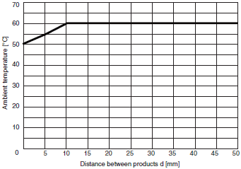
Relationship of Mounting Distance between K8DS-PH Relays and Ambient Temperature (Reference Values)
The following diagram shows the relationship between the mounting distances and the ambient temperature.
If the relay is used with an ambient temperature that exceeds these values, the temperature of the K8DS may rise and shorten the life of the internal components.

Test method
Sample: K8DS-PH
Distance between products: 0, 5, and 10 mm min.

last update: April 3, 2017
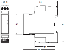
OMRON K8DS-PH dimension
K8DS-PH Phase-sequence Phase-loss Relay/Dimensionslast update: April 01, 2014
Phase-sequence Phase-loss Relay
K8DS-PH1

Optional Parts for DIN Track Mounting
DIN Tracks
PFP-100N
PFP-50N

last update: April 01, 2014
OMRON K8DS-PH lineup
K8DS-PH Phase-sequence Phase-loss Relay/Lineuplast update: April 01, 2014
| Function | Rated input voltage * | Relay output | Model |
|---|---|---|---|
| Phase sequence and phase loss monitoring | 3-phase, 3-wire 200 to 480 VAC | SPDT × 1 | K8DS-PH1 |
* The power supply voltage is the same as the rated input voltage.
last update: April 01, 2014
OMRON K8DS-PH catalog
K8DS-PH Phase-sequence Phase-loss Relay/Catalog- Catalog
- CAD
English
Global Edition
| Catalog Name | Catalog Number [size] | Last Update | |
|---|---|---|---|
| | N190-E1-01 [908KB] | Apr 03, 201720170403 | K8DS-PH Data Sheet |
| | N222-E1-01 [1649KB] | Jun 01, 201820180601 | Measuring and Monitoring Relays Application Guide |
- NO. K8DS-PH
- TYPE:Measuring / Motor Protective Relays Component Protective Components Measuring & Monitoring relays
- DATE:2021-06-09
- Associated products:
K8AK-PH Phase-sequence Phase-loss Relay/Features K8AK-PM Three-phase Voltage and Phase-sequence Phase-loss Relay/Features