OMRON A7BS / A7BLSwitches/ Thumbwheel Switches/ Copyright Statement
OMRON A7BS / A7BL Switches
OMRON A7BS / A7BL Dimensions
/Images/l_355-25-118545-198x198.jpglast update: December 19, 2013
• Character height of 4.8 or 3.2 mm makes for easy-toview display.
• Installation is easy with snap-in mounting.
• The series includes a complete range of locking-type models that prevent accidental operation.
last update: December 19, 2013
Purchase the OMRON Copyright Statement Please fill in the following
If you have just landed here, this product OMRON A7BS / A7BL Switches,Switches is offered online by Tianin FLD Technical Co.,Ltd. This is an online store providing Switches at wholesale prices for consumers. You can call us or send enquiry, we would give you the prices, packing,deliverty and more detailed information on the A7BS / A7BL We cooperate with DHL,TNT,FEDEX,UPS,EMS,etc.They guarantee to meet your needs in terms of time and money,even if you need your OMRON A7BS / A7BLSwitches tomorrow morning (aka overnight or next day air) on your desk, 2, 3 days or more.Note to international customers, YES, we ship worldwide.
NJ501-5300 NJ-series NC Integrated Controller/Features
CJ1W-NC[][]3 CJ series Position Control Units/Features
EE-SPW321 / 421 Photomicrosensor with Amplifier and Cable/Features
EE-SPX613 Pipe-mounting Liquid Level Photomicrosensor with Built-in Amplifier/Features
K3HB-H Temperature Indicator/Features
OMRON A7BS / A7BL catalog
A7BS / A7BL Thumbwheel Switch/Catalog- Catalog
- CAD
English
Global Edition
| Catalog Name | Catalog Number [size] | Last Update | |
|---|---|---|---|
| | - [498KB] | Apr 01, 201620160401 | A7BS, A7BL Data Sheet |
OMRON A7BS / A7BL dimension
A7BS / A7BL Thumbwheel Switch/Dimensionslast update: September 24, 2012
Switches
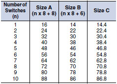
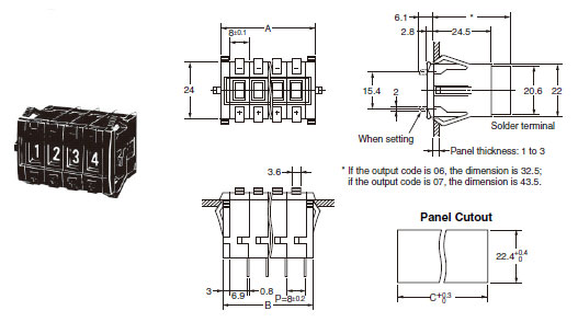
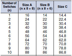
A7BS-2[][](-1)
Solder Terminals
![A7BS / A7BL Dimensions 3 A7BS-2[][](-1)_Dim](/images/8767/a7bs_a7bl_dm_125-111936.jpg)
Note:Note:
Note:The dimensions above include both End Caps, and will increase 8 mm for each Spacer inserted.
Note:Unless otherwise specified, a tolerance of ±0.4 mm applies to all dimensions.
The tolerance for multiple connection is ±(number of units x 0.4) mm.
Thumbwheel Switches with External Stoppers:
A7BS-20[]-S(-1)
Use A7BS-S Stopper Pins to make dial display restrictions for these Switches.
Insert the Stopper Pins in the positions required to give the desired display range. For example, for a display range of 0 to 5, insert a Stopper Pin at position 1 (see following diagram) to stop the display from going above 5 when the (+) button is pressed, and insert a Stopper Pin at position 2 to stop the display from going below 0 when the (-) button is pressed.
![A7BS / A7BL Dimensions 10 A7BS-20[]-S(-1)_Dim](/images/8767/355_dm_325-111940.gif)
Note:If the output code is 06, the dimension is 32.5;
if the output code is 07, the dimension is 43.5.
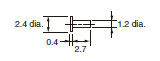
Stopper Pins
Note:Note:
Note:Two pins constitute one set.
Note:The first shipment is free and is attached to the Switch.
Order the A7BS-S separately if it is required for maintenance.
A7BL-206(-1)
A7BL-207(-1)
Solder Terminals,
Locking Models
Note:Note:
Note:The dimensions above include both End Caps, and will increase 8 mm for each Spacer inserted.
Note:Unless otherwise specified, a tolerance of ±0.4 mm applies to all dimensions.
The tolerance for multiple connection is ±(number of units x 0.4) mm.
Accessories (Order Separately)
End Caps for Push-operated Switches
A7B-M(-1) Snap-in Panel Mounting
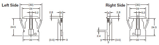
Spacers for Push-operated Switches
A7B-P[](-1) Snap-in Panel Mounting
_Dim](/images/8767/a7bs_a7bl_dm_825-111950.jpg)
Note:The [] in the Spacer model number stands for a letter in the range A to U. (Refer to the table under the explanation about Spacers on Lineup.)
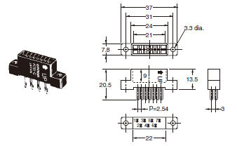
Connectors
Note:(These devices allow Switches to be quickly removed for maintenance and inspection of connectivity, and quickly re-installed.)
A7B-C
Solder Terminals
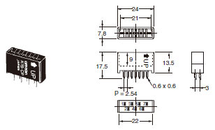
A7B-CP
PCB Terminals
Inserting Connectors
Insert Connectors with the "UP" arrow pointing up.
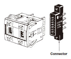
Note:Unless otherwise indicated, dimensional tolerances for dimensions in the models above are ± 0.4 mm.
last update: September 24, 2012
OMRON A7BS / A7BL specification
A7BS / A7BL Thumbwheel Switch/Specificationslast update: August 20, 2014
| Switching capacity (resistive load) | 3.3 to 28 VDC or 50 VAC 1 mA to 0.1 A | |
|---|---|---|
| Continuous carry current | 1 A max. | |
| Contact resistance | 300 mΩ max. | |
| Insulation resistance | Between non-connected terminals | 10 MΩ min. (at 500 VDC) |
| Between terminal and non-current carrying part | 1,000 MΩ min. (at 500 VDC) | |
| Dielectric strength | Between non-connected terminals | 600 VAC, 50/60 Hz for 1 min |
| Between terminal and non-current carrying part | 1,000 VAC, 50/60 Hz for 1 min | |
| Vibration resistance | 10 to 55 Hz, 1.5-mm double amplitude | |
| Shock resistance | 490 m/s2 min. | |
| Durability | Mechanical | 100,000 operations min. |
| Electrical | 50,000 operations min. | |
| Ambient temperature | Operating: -10°C to 65°C (with no icing) Storage: -20°C to 80°C | |
| Ambient humidity | Operating: 45% to 85% | |
| Max. operating force | 5.39 N max. | |
last update: August 20, 2014
OMRON A7BS / A7BL lineup
A7BS / A7BL Thumbwheel Switch/Lineuplast update: April 01, 2016
Switches (Single Switch Units)
| Model | A7BS | A7BS-20[]-S | ||
|---|---|---|---|---|
| Classification (See note 1.) | Snap-in (front mounting)  | Snap-in (front mounting) With external stoppers  | ||
| Character height | Decimal: 4.8 mm Hexadecimal: 3.2 mm | 4.8 mm | ||
| Terminals | Solder terminals *1 | |||
| Color | Light gray | Black | Light gray | Black |
| Output code number | Model | |||
| 06 (binary coded decimal) | A7BS-206 *2 | A7BS-206-1 *2 | A7BS-206-S | A7BS-206-S-1 |
| 07 (binary coded decimal, with component adding provision) *3 | A7BS-207 *2 | A7BS-207-1 *2 | A7BS-207-S | A7BS-207-S-1 |
| 54 (binary coded hexadecimal) | A7BS-254 | A7BS-254-1 | --- | --- |
| 55 (binary coded hexadecimal, with component-adding provision) *3 | A7BS-255 | A7BS-255-1 | --- | --- |
| Model | A7BL | |
|---|---|---|
| Classification (See note 1.) | Snap-in (front mounting) Locking type  | |
| Character height | 4.8 mm | |
| Terminals | Solder terminals *1 | |
| Color | Light gray | Black |
| Output code number | Model | |
| 06 (binary coded decimal) | A7BL-206 *2 | A7BL-206-1 *2 |
| 07 (binary coded decimal, with component-adding provision) *3 | A7BL-207 *2 | A7BL-207-1 *2 |
Note: 1. The classification diagrams show 4 Switch Units combined with End Caps to create 4-digit displays.
2. The model numbers given above are for Switch Units.
3. Models with +, - displays can also be produced. Add “-PM” after the “206” or “207” in the model number
(e.g., A7BS-206-PM or A7BS-207-PM-1).
*1. For models with PCB terminals, add “-P2” to the model number (e.g., A7BS-207-P2-1).
*2. Models with internal stoppers are also available. Add “-S[][]” after the “206” or “207” in the model number and specify
the display range in the [][]. For example, to specify the range 0 to 6, add “-S06” to the model number (e.g.,
A7BS-206-S06-1).
For structural reasons, models with stoppers cannot be manufactured for the A7BS-254 and A7BS-255.
*3. Models with diodes are available. Add “-D” to the model number (e.g., A7BS-207-D or A7BS-207-D-1).
Accessories (Order Separately)
Use accessories, such as End Caps, Spacers, and Connectors with the Switch Units.
End Caps, Spare Units, and Connectors
| Accessory | Color | Light gray | Black |
|---|---|---|---|
| End Caps (1 pair) | A7B-M | A7B-M-1 | |
| Spacer | A7B-P[] * | A7B-P[]-1 * | |
| Connectors | Solder terminals | A7B-C | |
| PCB terminals | A7B-CP | ||
* The [] in the Spacer model number stands for a letter in the range A to U. (Refer to the table in the following
explanation about Spacers.)
End Caps
End Caps are used on the Switch Units at each end and allow all the Switch Units to be securely mounted to a panel. They come in pairs, one for the left and one for the right.
Spacers
- Spacers are used for creating extra space or gaps between the Switch Units and have the same dimensions as the Switch Units themselves.
- There are also Spacers with engraved characters or symbols that can be used for indicating units, such as time and length. (Refer to the following table.) Consult your OMRON representative for details.
| Symbol | A | B | C | D | E | F | G | H | J | K | L | Q | T | U |
|---|---|---|---|---|---|---|---|---|---|---|---|---|---|---|
| Stamp | No designation | SEC | MIN | H | g | kg | mm | cm | m | °C | PCS | x 10 SEC | 0 | ● |
last update: April 01, 2016
- NO. A7BS / A7BL
- TYPE:Thumbwheel Switches Copyright Statement Copyright Statement
- DATE:2021-06-12
- Associated products:
A7CN / A7CN-L Thumbwheel Switch/Features A7PS / A7PH Thumbwheel Switch/Features