OMRON KM-N3-FLKEnergy Conservation Support / Environment Measure Equipment/ Electric Power Monitoring Equipment/Smart Power Monitor
OMRON KM-N3-FLK Energy Conservation Support / Environment Measure Equipment
OMRON KM-N3-FLK Dimensions
/Images/l_3649-25-268533-198x198.jpglast update: September 11, 2017
The New KM-N2 and KM-N3 Power Monitors
Energy management starts by continuously monitoring power.
The KN-N2 and KN-N3 enable all types of power measurement with easy installation and easy system construction.
You can mount them on or in control panels and distribution boards and take advantage of their compatibility with power supplies around the world.

Many Host Communications Methods

Multi-address System

Push-In Plus Terminal Block
The structure of Push-In Plus terminal blocks helps reduce wiring mistakes with easy-to-insert terminals that hold wires firmly (RS-485 communications and pulse output terminals).

Efficient Initial Setting Tool *1
- Easy-to-use setting functions of the communications and measurement conditions
- Save/Load setting by CSV file

*1. Supported Version of main unit: V2.0.0 or higher for all models.
*2. Except for KM-N2-FLK.
*3. For this software, compatibility of the USB/RS-485 converter has been verified for SI-35USB (LINEEYE Co.,Ltd.). K3SC-10 is not compatible.
Wiring Error Detection

last update: September 11, 2017
Purchase the OMRON Smart Power Monitor Please fill in the following
If you have just landed here, this product OMRON KM-N3-FLK Energy Conservation Support / Environment Measure Equipment,Energy Conservation Support / Environment Measure Equipment is offered online by Tianin FLD Technical Co.,Ltd. This is an online store providing Energy Conservation Support / Environment Measure Equipment at wholesale prices for consumers. You can call us or send enquiry, we would give you the prices, packing,deliverty and more detailed information on the KM-N3-FLK We cooperate with DHL,TNT,FEDEX,UPS,EMS,etc.They guarantee to meet your needs in terms of time and money,even if you need your OMRON KM-N3-FLKEnergy Conservation Support / Environment Measure Equipment tomorrow morning (aka overnight or next day air) on your desk, 2, 3 days or more.Note to international customers, YES, we ship worldwide.
K3SC Interface Converter/Features
CS1W-CIF31 USB-Serial Conversion Cable/Features
NJ501-4[][][] NJ-series NJ Robotics CPU Units/Features
D4NL Guard Lock Safety-door Switch/Features
CRT1-AD04 / DA02 Analog I/O Slave Units/Features
OMRON KM-N3-FLK specification
KM-N3-FLK Power Monitor/Specificationslast update: October 1, 2018
Ratings (Power Monitor)
| Model | KM-N3-FLK | |
|---|---|---|
| Applicable phase wiring methods | Single-phase two-wire, single-phase three-wire, three-phase three-wire, and three-phase four-wire | |
| Number of measured circuits | Single-phase two-wire: 4 circuits max., Single-phase three-wire or three- phase three-wire: 2 circuits max., Three-phase four-wire: 1 circuit | |
| Power supply voltage (operating frequency) | 100 to 240 VAC (50/60 Hz) | |
| Power supply allowable voltage range | 85% to 110% of rated power supply voltage | |
| Power consumption | 7 VA max. | |
| Input | Rated input voltages | Single-phase, 2-wire: 100 to 277 VAC Single-phase, 3-wire: 100 to 240 VAC (L-N) or 200 to 480 VAC (L-L) Three-phase, 3-wire: 173 to 480 VAC (L-L) Three-phase, 4-wire: 100 to 277 VAC (L-N) or 173 to 480 VAC (L-L) |
| Allowable supply voltage range | 85% to 115% of rated power supply voltage | |
| Connectable CTs | General-purpose CT with a rated secondary current of 1 A or 5 A * | |
| Maximum CT secondary current | 6 A | |
| Rated input frequency | 50/60 Hz | |
| Ambient operating temperature | -25 to 55°C (with no condensation or icing) | |
| Ambient operating humidity | 25% to 85% | |
| Storage temperature | -25 to 85°C (with no condensation or icing) | |
| Storage humidity | 25% to 85% | |
| Operating altitude | 2,000 m max. | |
| Installation environment | Overvoltage category II, measurement category II, pollution degree 2 | |
| Electromagnetic environment | Industrial electromagnetic environment (EN/IEC 61326-1 Table 2) | |
| Compliant standards | EN 61010-2-030, EN 61326-1, and UL 61010-1 | |
* The KM-series CTs (the KM20-CTF or KM-NCT Series) cannot be used. Use general-purpose CTs with a secondary-side output of 1 A or 5 A.
Split Type Current Transformer (CT) (CE marking compliant KM-N2/N3 dedicated products *)
| Item | KM-NCT-E100A | KM-NCT-E250A | KM-NCT-E500A |
|---|---|---|---|
| Rated primary current: In | 100 A | 250 A | 500 A |
| Rated secondary current: Is | 1 A | ||
| Rated frequency | 50/60 Hz | ||
| Cable Length | Please refer to Writing to KM-NCT-E[][][]A | ||
| Rated load | 1 VA | ||
| Insulation resistance | 100 MΩ min. (at 500 VDC mega) between core and all output terminals | ||
| Dielectric strength voltage | 2300 VAC, 1 minute between core and all output terminals. | ||
| Weight | Approx. 170 g | Approx. 175 g | Approx. 290 g |
| Maximum wire diameter | 24 dia. | 24 dia. | 36 dia. |
| Operating temperature and humidity range | -20 to 55 °C, relative humidity: 85% max. with no condensation | ||
| Storage temperature and humidity range | -30 to 90 °C, relative humidity: 85% max. with no condensation | ||
| Applicable standards * | EN61010-1, EN61010-2-030, EN61326-1 | ||
| Installation environment | Overvoltage category and measurement category:Ⅱ, Pollution level: 2 | ||
* The KM-NCT-E conforms to the standards shown above ONLY when it is used with a power monitor KM-N2-FLK or KM-N3-FLK to which it is attached. Use of the KM-NCT-E without a power monitor does not conform to these standards.
Wiring to KM-NCT-E[][][]A
• For wiring of the output terminal of CT, use AWG18-14 electric wire (with a cross-section of 0.75-2.0mm2) and Y-shape terminal compatible with the M3 screw.
• The recommended torque for screwing the M3 screws onto the output terminal is 0.3 N·m. Make sure the Y terminal is pushed all the way in and tightened firmly. After fixing the wiring, confirm that the wire is fixed securely.
• The guideline of the maximum wiring length between KM-N2-FLK or KM-N3-FLK and KM-NCT-E is as follows.
The longer the wire length, the larger the measurement error using the KM-NCT-E becomes.
• The limit of the wiring length can also be calculated by the following formula. Calculate the wiring length limit according to the conductor resistivity of the wiring and keep the wiring length below the limit.
• The limits of the wiring length shown below are for reference only. They do not guarantee proper use.
| Wiring diameter | Guideline for wiring length limit |
|---|---|
| 0.75 mm2 (AWG18 equivalent) | 15 m |
| 2.0 mm2 (AWG14 equivalent) | 43 m |
Wiring extension limit value (one-way) (m)= 0.475/conductor resistivity (Ω/m)
Note: Select a CT cable that does not exceed the rated load of 1 VA.
Performance (Power Monitor)
| Model | KM-N3-FLK | |
|---|---|---|
| Measured items | Total power consumption (active, regenerative, and reactive), power (active and reactive), current, voltage, power factor, and frequency | |
| Meas- urement specifi- cations | Active power | 0.5% (IEC 62053-22 class 0.5S * |
| Reactive power | 2% (IEC 62053-23 class 2) * | |
| Sampling cycle | 80 ms for 50 Hz and 66.7 ms for 60 Hz | |
| Insulation resistance | (1) Between all electrical circuits and the case: 20 MΩ min. (at 500 VDC) (2) Between all power supply and voltage inputs and all communications and pulse output terminals: 20 MΩ max. (at 500 VDC) | |
| Dielectric strength | (1) Between all electrical circuits and the case: 1,400 VAC for 1 min (2) Between all voltage and current inputs and all communications and pulse output terminals: 1,400 VAC for 1 min | |
| Vibration resistance | Single amplitude: 0.1 mm, Acceleration: 15 m/s2, Frequency: 10 to 150 Hz, 10 sweeps for 8 min each along three axes | |
| Shock resistance | 150 m/s2, 3 times each in 6 directions (up/down, left/right, forward/backward) | |
| Indications and operation method | LCD indications and operation buttons | |
| Weight | Approx. 350 g (Power Monitor only) | |
| Degree of protection | Front: IP65, Rear case: IP20, Terminal: IP00 | |
| Pulse output | Number of outputs | Number of outputs: 4 (photoMOS relay outputs) Used for the total power consumption pulse output. |
| Output capacity | 50 mA at 40 VDC ON residual voltage: 1.5 V max. (for output current of 50 mA) OFF leakage current: 0.1 mA max. | |
| Output unit | Output unit: 1, 10, 100, 1k, 5k, 10k, 50k, or 100k (wh) Pulse ON time: 500 ms (Cannot be changed.) | |
| Commu- nications interface | Communications method | RS-485 (2-wire half-duplex with start-stop synchronization) |
| Communications protocol | Modbus (RTU): Binary. CompoWay/F: ASCII | |
| Baud rate | 1.2, 2.4, 4.8, 9.6, 19.2, or 38.4 kbps | |
| Data length | Data length: 7 or 8 bits Stop bits: 1 or 2 bits Vertical parity: Even, odd, or none | |
| Maximum transmission distance | 1,200 m | |
| Maximum number of connected Power Monitors | Modbus: 99, CompoWay/F: 31 If you measure more than one circuit with one Power Monitor, the number of circuits is treated as the number of connected Power Monitors. | |
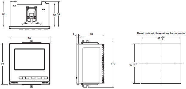
| Dimensions (H×W×D) | 96 × 96 × 64 mm (excluding protrusions) | |
| Installation method | On-panel installation | |
| Accessories | Instruction Manual and Compliance Sheet, Mounting adapter and waterproof packing | |
* The error of the CT or VT is not included. IEC 62053 is an international standard for power metering.
last update: October 1, 2018
OMRON KM-N3-FLK lineup
KM-N3-FLK Power Monitor/Lineuplast update: October 1, 2018
Power Monitor
| Model | Applicable phase wiring methods | Power supply voltage | Dimensions | Communications |
|---|---|---|---|---|
| KM-N3-FLK | Single-phase, 2-wire: 100 to 277 VAC Single-phase, 3-wire: 100 to 240 VAC (L-N) or 200 to 480 VAC (L-L) Three-phase, 3-wire: 173 to 480 VAC (L-L) Three-phase, 4-wire: 100 to 277 VAC (L-N) or 173 to 480 VAC (L-L) | 100 to 240 VAC Separate from measurement voltage. | 96 × 96 × 64 mm (H×W×D) (excluding protrusions) | RS-485 communications, pulse output |
To use a commercially available current transformer, use a CT with a secondary current rating of 1 A or 5 A, and a rated load of at least 1.0 VA.
Optional Products (Order Separately)
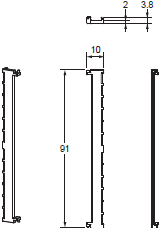
Terminal Covers
| Model |
|---|
| E53-COV24 (3pcs) |
Waterproof Packing
| Model |
|---|
| Y92S-P10 |
Note: This Waterproof Packing is provided with the KM-N3.
Mounting Adapter
| Model |
|---|
| Y92F-51 (2pcs) |
Note: This Mounting Adapter is provided with the KM-N3.
Split Type Current Transformer (CT) (CE marking compliant KM-N2/N3 dedicated products *)
| Model | Rated primary current | Rated secondary current |
|---|---|---|
| KM-NCT-E100A | 100 A | 1 A |
| KM-NCT-E250A | 250 A | |
| KM-NCT-E500A | 500 A |
* The KM-NCT-E conforms to the standards shown above ONLY when it is used with a power monitor KM-N2-FLK or KM-N3-FLK to which it is attached. Use of the KM-NCT-E without a power monitor does not conform to these standards.
Note: Select a CT cable that does not exceed the rated load of 1 VA.
last update: October 1, 2018
OMRON KM-N3-FLK catalog
KM-N3-FLK Power Monitor/Catalog- Catalog
- Manual
- CAD
English
Global Edition
| Catalog Name | Catalog Number [size] | Last Update | |
|---|---|---|---|
| | N213-E1-05 [7696KB] | Feb 01, 201920190201 | KM-N2 / KM-N3 Catalog |
| | Y218-E1-03 [13592KB] | Oct 02, 201720171002 | Innovation in Control Panel Building |
OMRON KM-N3-FLK dimension
KM-N3-FLK Power Monitor/Dimensionslast update: October 1, 2018
(Unit: mm)
Power Monitor
KM-N3-FLK
KM-NCT-E100A
KM-NCT-E250A
KM-NCT-E500A
(CE marking compliant KM-N2/N3 dedicated products *)
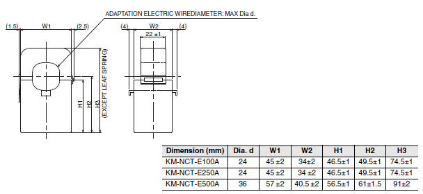
* The KM-NCT-E conforms to the standards shown above ONLY when it is used with a power monitor KM-N2-FLK or KM-N3-FLK to which it is attached. Use of the KM-NCT-E without a power monitor does not conform to these standards.
Optional Products (Order Separately)
Terminal Covers
E53-COV24 (Three Covers provided.)
Waterproof Packing
Y92S-P10 (for DIN 96 × 96)

The Waterproof Packing is provided with the KM-N3.
Order the Waterproof Packing separately if it becomes lost or damaged.
The Waterproof Packing for the front-panel Setup Tool port must be periodically replaced because they may deteriorate, shrink, or harden depending on the operating environment.
The replacement period will vary with the operating environment.
Check the required period in the actual application.
Use 3 years or sooner as a guideline.
Mounting Adapter
Y92F-51 (Two Adapters provided.)
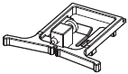
One pair is provided with the KM-N3.
Order this Adapter separately if it becomes lost or damaged.
last update: October 1, 2018
- NO. KM-N3-FLK
- TYPE:Electric Power Monitoring Equipment Smart Power Monitor
 Copyright Statement
 - DATE:2021-06-12
- Associated products:
ZN-CTX / CTM Portable Power Monitor/Features KM-N2-FLK Power Monitor/Features