
OMRON G7SASafety Components/ Safety Relays/ Copyright Statement
OMRON G7SA Safety Components
OMRON G7SA Dimensions
/Images/l_386-25-118877-198x198.jpglast update: April 2, 2018
• Additional Push-In Plus terminal sockets are used to save wiring work in comparison with traditional screw terminals.
(Wiring time is reduced by 60%* in comparison with traditional screw terminals.)
• Relays with forcibly guided contacts (EN/IEC 61810-3, Certified by VDE).
• Supports the CE marking of machinery (Machinery Directive).
• Helps avoid hazardous machine status when used as part of an interlocking circuit.
• Four-pole and six-pole Relays are available.
• The Relay’s terminal arrangement simplifies PWB pattern design.
• Reinforced insulation between inputs and outputs. Reinforced insulation between some poles of different polarity.
* According to OMRON actual measurement data
last update: April 2, 2018
Purchase the OMRON  Copyright Statement Please fill in the following
If you have just landed here, this product OMRON G7SA Safety Components,Safety Components is offered online by Tianin FLD Technical Co.,Ltd. This is an online store providing Safety Components at wholesale prices for consumers. You can call us or send enquiry, we would give you the prices, packing,deliverty and more detailed information on the G7SA We cooperate with DHL,TNT,FEDEX,UPS,EMS,etc.They guarantee to meet your needs in terms of time and money,even if you need your OMRON G7SASafety Components tomorrow morning (aka overnight or next day air) on your desk, 2, 3 days or more.Note to international customers, YES, we ship worldwide.
E2K-F Flat Proximity Sensor/Features
CS1W-LCB01 / LCB05 Loop Control Boards/Features
NX-TS NX-series Temperature Input Unit/Features
NX-CIF NX-series Communications Interface Units/Features
CJ1W-ETN21 CJ-series Ethernet Unit/Features
OMRON G7SA lineup
G7SA Relays with Forcibly Guided Contacts/Lineuplast update: October 16, 2018
Main unit
Relays with Forcibly Guided Contacts
Specify the coil rated voltage when ordering.
| Terminal type | Sealing | Poles | Contact configuration | Coil rated voltage | Model |
|---|---|---|---|---|---|
| PCB terminals | Flux-tight | 4 poles | 3PST-NO, SPST-NC | 12, 18, 21, 24, 48, 110 VDC | G7SA-3A1B |
| DPST-NO, DPST-NC | 12, 18, 21, 24, 48, 110 VDC | G7SA-2A2B | |||
| 6 poles | 5PST-NO, SPST-NC | 12, 18, 21, 24, 48, 110 VDC | G7SA-5A1B | ||
| 4PST-NO, DPST-NC | 12, 18, 21, 24, 48, 110 VDC | G7SA-4A2B | |||
| 3PST-NO, 3PST-NC | 12, 18, 21, 24, 48, 110 VDC | G7SA-3A3B |
Options (order separately)
Sockets
| Mounting | Terminal Type | LED Indicator | Poles | Coil rated voltage | Appearance | Model |
|---|---|---|---|---|---|---|
| Front-mounting | Push-In Plus terminals | Yes | 4 poles | 24 VDC |  | P7SA-10F-ND-PU |
| 6 poles |  | P7SA-14F-ND-PU | ||||
| Screw terminals | Yes | 4 poles |  | P7SA-10F-ND | ||
| 6 poles |  | P7SA-14F-ND | ||||
| No | 4 poles | - |  | P7SA-10F | ||
| 6 poles |  | P7SA-14F | ||||
| Back-mounting | PCB terminals | No | 4 poles | - |  | P7SA-10P |
| 6 poles |  | P7SA-14P |
Socket Accessories
Short Bars (For P7SA-[]F-ND-PU)
| Pitch | No. of poles | Colors | Model*1*2 |
|---|---|---|---|
| 5.2 mm | 2 | Red (RD) Blue (BL) Yellow (YL) | XW5S-P2.5-2[] |
| 3 | XW5S-P2.5-3[] | ||
| 4 | XW5S-P2.5-4[] | ||
| 5 | XW5S-P2.5-5[] |
Note: Use for crossover wiring of adjacent contact terminals (bottom) within one Socket.
*1. Replace the box ([]) in the model number with the code for the covering color.
Color Options: RD = red, BL = blue, YL = yellow
Example: XW5S-P2.5-10RD when the covering color is red.
*2. XW5S-P2.5-5[] cannot be used with P7SA-10F-ND-PU.
Parts for DIN Track Mounting
| Type | Model | Minimum Order (quantity) | |
|---|---|---|---|
| DIN Tracks | 1 m | PFP-100N | 1 |
| 0.5 m | PFP-50N | ||
| End Plate * | PFP-M | 10 | |
| Spacer | PFP-S | ||
* When mounting DIN track, please use End Plate (Model PFP-M).
last update: October 16, 2018
OMRON G7SA dimension
G7SA Relays with Forcibly Guided Contacts/Dimensionslast update: April 2, 2018
(Unit: mm)
Safety Relay Unit
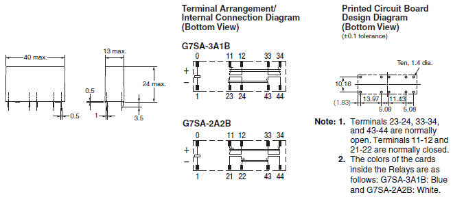
4 poles
G7SA-3A1B
G7SA-2A2B
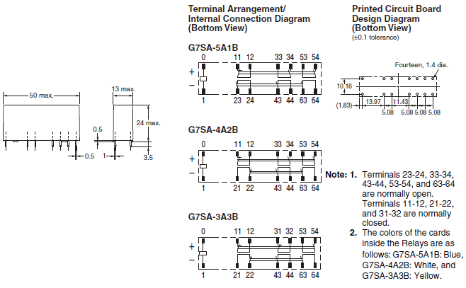
6 poles
G7SA-5A1B
G7SA-4A2B
G7SA-3A3B
Options (order separately)
Sockets
Front-mounting Sockets
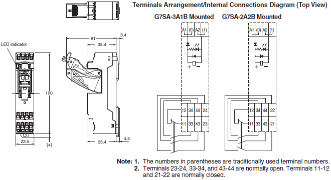
Push-In Plus terminals 4 poles
P7SA-10F-ND-PU
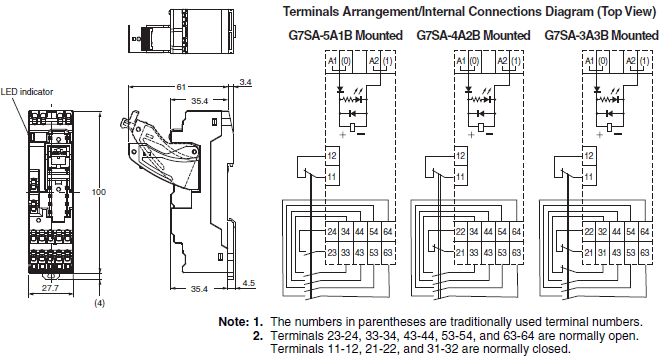
Push-In Plus terminals 6 poles
P7SA-14F-ND-PU
Accessories for Push-In Plus Sockets
Short Bars (for P7SA-[]F-ND-PU)
XW5S-P2.5-[][]

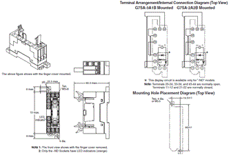
Front-mounting Sockets
Screw terminals 4 poles
P7SA-10F, P7SA-10F-ND
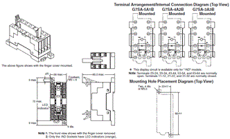
Screw terminals 6 poles
P7SA-14F, P7SA-14F-ND
Parts for DIN Track Mounting
DIN Track
PFP-100N
PFP-50N

DIN Track
PFP-100N2

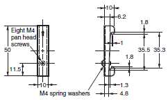
End Plate
PFP-M
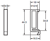
Spacer
PFP-S
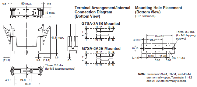
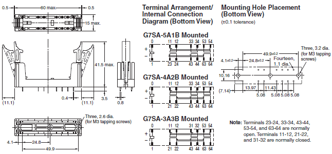
Back-mounting Sockets (for PCB)
PCB terminals 4 poles
P7SA-10P
PCB terminals 6 poles
P7SA-14P
last update: April 2, 2018
OMRON G7SA catalog
G7SA Relays with Forcibly Guided Contacts/Catalog- Catalog
- CAD
English
Global Edition
| Catalog Name | Catalog Number [size] | Last Update | |
|---|---|---|---|
| | J120-E1-04 [2973KB] | Nov 02, 201820181102 | G7SA Data Sheet |
| | J213-E1-05 [7147KB] | Nov 01, 201820181101 | Push-In Plus Terminal Block Series Pamphlet |
| | Y218-E1-03 [13592KB] | Oct 02, 201720171002 | Innovation in Control Panel Building |
OMRON G7SA specification
G7SA Relays with Forcibly Guided Contacts/Specificationslast update: November 2, 2018
Ratings
Safety Relay Unit
Coil (4 poles)
| Item | Rated current (mA) | Coil resistance (Ω) | Max. voltage (V) | Power consumption (mW) |
|---|---|---|---|---|
| Rated voltage | ||||
| 12 VDC | 30 | 400 | 110% | Approx. 360 |
| 18 VDC | 20 | 900 | ||
| 21 VDC | 17.1 | 1,225 | ||
| 24 VDC | 15 | 1,600 | ||
| 48 VDC | 7.5 | 6,400 | ||
| 110 VDC | 3.8 | 28,810 | Approx. 420 |
Coil (6 poles)
| Item | Rated current (mA) | Coil resistance (Ω) | Max. voltage (V) | Power consumption (mW) |
|---|---|---|---|---|
| Rated voltage | ||||
| 12 VDC | 41.7 | 288 | 110% | Approx. 500 |
| 18 VDC | 27.8 | 648 | ||
| 21 VDC | 23.8 | 882 | ||
| 24 VDC | 20.8 | 1,152 | ||
| 48 VDC | 10.4 | 4,606 | ||
| 110 VDC | 5.3 | 20,862 | Approx. 580 |
Note: 1. The rated current and coil resistance are measured at a coil temperature of 23°C with tolerances of ±15%.
2. The maximum voltage is based on an ambient operating temperature of 23°C maximum.
Contacts
| Load | Resistive load |
|---|---|
| Rated load | 6 A at 250 VAC, 6 A at 30 VDC |
| Rated carry current | 6 A |
| Max. switching voltage | 250 VAC, 125 VDC |
| Max. switching current | 6 A |
| Contact materials | Au plating + Ag alloy |
Characteristics
Safety Relay Unit
| Contact resistance *1 | 100 mΩ max. | |
|---|---|---|
| Operating time *2 | 20 ms max. | |
| Response time *3 | 10 ms max. | |
| Release time *2 | 20 ms max. | |
| Must operate voltage | 75% max. | |
| Must release voltage | 10% min. | |
| Maximum operating frequency | Mechanical | 36,000 operations/h |
| Rated load | 1,800 operations/h | |
| Insulation resistance *4 | 1,000 MΩ min. | |
| Dielectric Strength *5 *6 | Between coil and contacts | 4,000 VAC, 50/60 Hz for 1 min. |
| Between contacts of different olarity | 4,000 VAC, 50/60 Hz for 1 min. (except for followings) 4 poles (for poles 3-4 in 4-pole Relays), 6 poles (for poles 3-5, 4-6, and 5-6 in 6-pole Relays): 2,500 VAC, 50/60 Hz for 1 min. | |
| Between contacts of the same polarity | 1,500 VAC, 50/60 Hz for 1 min. | |
| Vibration resistance | 10 to 55 to 10 Hz, 0.75-mm single amplitude (1.5-mm double amplitude) | |
| Shock resistance | Destruction | 1,000 m/s2 |
| Malfunction | 100 m/s2 | |
| Durability *7 | Mechanical | 10,000,000 operations min. (at approx. 36,000 operations/h) |
| Electrical | 100,000 operations min. (at the rated load) | |
| Inductive load switching capability *8 (IEC60947-5-1) | AC15 240 VAC, 2 A DC13 24 VDC, 1 A/48 VDC, 0.5 A/110 VDC, 0.2 A | |
| Failure rate (P level) (reference value *9) | 5 VDC, 1 mA | |
| Ambient operating temperature *10 | 12 to 48 VDC: -40 to 85°C (with no icing or condensation) 110 VDC: -40 to 60°C (with no icing or condensation) | |
| Ambient operating humidity | 5% to 85% | |
| Weight | 4 poles: Approx. 22 g 6 poles: Approx. 25 g | |
Note: 1. The above values are initial values.
2. Performance characteristics are based on coil temparature of 23°C.
*1. The contact resistance was measured with 1 A at 5 VDC using the voltage-drop method.
*2. These times were measured at the rated voltage and an ambient temperature of 23°C. Contact bounce time is not
included.
*3. The response time is the time it takes for the normally open contacts to open after the coil voltage is turned OFF.
Contact bounce time is included. Measurement conditions: Rated voltage operation, Ambient temperature: 23°C
*4. The insulation resistance was measured with a 500-VDC megohmmeter at the same locations as the dielectric
strength was measured.
*5. Pole 3 refers to terminals 31-32 or 33-34, pole 4 refers to terminals 43-44, pole 5 refers to terminals 53-54, and
pole 6 refers to terminals 63-64.
*6. When using a P7SA Socket, the dielectric strength between coil contacts/different poles is 2,500 VAC, 50/60 Hz for
1 min. When using Push-In Plus terminal sockets (P7SA-[]F-ND-PU), the dielectric strength between coil contacts
as well as between different poles is 4,000 VAC, 50/60 Hz for 1 min.
*7. The durability is for an ambient temperature of 15 to 35°C and an ambient humidity of 25% to 75%. For the durability
performance to the load, refer to the Durability Curve.
*8. AC15: cosφ = 0.3, DC13: L/R = 48-ms.
*9. The failure rate is based on an operating frequency of 300 operations/min.
*10. 12 to 48 VDC:
When operating between 70 and 85°C, reduce the rated carry current of 6 A by 0.1 A for each degree above 70°C.
110 VDC:
When operating between 40 and 60°C, reduce the rated carry current of 6 A by 0.27 A for each degree above 40°C.
Options (order separately)
Sockets
| Model | Push-In Plus terminals | Screw terminals | PCB terminals | ||||
|---|---|---|---|---|---|---|---|
| 4 poles | 6 poles | 4 poles | 6 poles | 4 poles | 6 poles | ||
| P7SA-10F-ND-PU | P7SA-14F-ND-PU | P7SA-10F(-ND) | P7SA-14F(-ND) | P7SA-10P | P7SA-14P | ||
| Ambient operating temperature | • With operation indicator LED/built-in diode P7SA-[]F-ND(-PU): -20 to +70°C • Without operation indicator LED/built-in diode P7SA-[]F: -40 to +85°C (with no icing or condensation) | -40 to +85°C (with no icing or condensation) | |||||
| Ambient operating humidity | 25% to 85% | 5% to 85% | |||||
| Continuous carry current | 6 A *1 | ||||||
| Dielectric strength | Between coil and contact terminals | 4,000 VAC for 1 min. | 2,500 VAC for 1 min. | ||||
| Between contact terminals of different polarity | 2,500 VAC for 1 min. | ||||||
| Between contact terminals of same polarity | 1,500 VAC for 1 min. | ||||||
| Insulation resistance | 1,000 MΩ min. *2 | ||||||
| Weight | Approx. 58 g | Approx. 70 g | Approx. 44 g | Approx. 59 g | Approx. 9 g | Approx. 10 g | |
*1. When operating the P7SA-[]F-ND-PU at a temperature between 50 and 70°C, reduce the continuous current
(6 A at 50°C or less) by 0.25 A for each degree above 50°C.
When operating the P7SA-[]F-ND at a temperature between 50 and 70°C, reduce the continuous current
(6 A at 50°C or less) by 0.3 A for each degree above 50°C.
When operating the P7SA-[]F at a temperature between 50 and 85°C, reduce the continuous current
(6 A at 50°C or less) by 0.1 A for each degree above 50°C.
*2. Measurement conditions: For 500 VDC applied to the same location as for dielectric strength measurement.
Short Bars (for P7SA-[]F-ND-PU)
| Application | Applicable sockets | Models | Maximum carry current | Ambient operating temperature | Ambient operating humidity |
|---|---|---|---|---|---|
| Crossover wiring of contact terminals (bottom) | P7SA-[]F-ND-PU | XW5S-P2.5-2[] | 24 A | -40 to 55°C | 5% to 95% |
| XW5S-P2.5-3[] | |||||
| XW5S-P2.5-4[] | |||||
| XW5S-P2.5-5[] |
last update: November 2, 2018
- NO. G7SA
- TYPE:Safety Relays
 Copyright Statement
  Copyright Statement
 - DATE:2021-06-09
- Associated products:
A4E Enabling Switch/Features G7S-[]-E Relays with Forcibly Guided Contacts/Features