OMRON E3X-DA-NSensors/ Fiber Sensors/Fiber Amplifier
OMRON E3X-DA-N Sensors
OMRON E3X-DA-N Dimensions
/Images/l_398-25-118737-198x198.jpglast update: December 19, 2013
Models with New Connector System Reduces Wiring, Saves Space, and Makes Maintenance Easier (First in the Industry) (Patent Pending)
In Amplifiers with wire-saving connectors, the power supply is distributed to 1-conductor slave connectors through a 3-conductor master connector. This design has three major advantages.
1.Wiring time is significantly reduced.
2.Relay connectors are unnecessary, so wiring takes up less space and costs are reduced.
3.Storage and maintenance are simpler because it isn't necessary to distinguish between master connector and slave connectors on the Amplifier.
Further Developing the Ultimate Power of Fiber Amplifiers.Remote Setting and Adjustment
Perform settings, teaching, and fine adjustments at the end of the Fiber Unit.

With group teaching, teach multiple amplifiers simultaneously.

Eliminate inconsistency by using group zero reset.

Flash the Sensor head and display the amplifier channels during operation.

Display the light intensity and threshold at the same time.

last update: December 19, 2013
Purchase the OMRON Fiber Amplifier Please fill in the following
If you have just landed here, this product OMRON E3X-DA-N Sensors,Sensors is offered online by Tianin FLD Technical Co.,Ltd. This is an online store providing Sensors at wholesale prices for consumers. You can call us or send enquiry, we would give you the prices, packing,deliverty and more detailed information on the E3X-DA-N We cooperate with DHL,TNT,FEDEX,UPS,EMS,etc.They guarantee to meet your needs in terms of time and money,even if you need your OMRON E3X-DA-NSensors tomorrow morning (aka overnight or next day air) on your desk, 2, 3 days or more.Note to international customers, YES, we ship worldwide.
F3W-D Picking Sensor/Features
E2CY-SD Non-ferrous-metal-detecting Proximity Sensor (Separate Amplifier Type)/Features
E6C3-C Rugged Incremental 50-mm-dia. Rotary Encoder/Features
H3DT-H Power OFF-delay Timer/Features
CS1W-AT2[][] C200H I/O Terminal Block Conversion Adapter/Features
OMRON E3X-DA-N lineup
E3X-DA-N Digital Fiber Amplifier/Lineuplast update: April 01, 2016
Amplifiers
Pre-wired Amplifiers
| Type | Appearance | Control output | Model | |
|---|---|---|---|---|
| NPN output | PNP output | |||
| Standard models |  | ON/OFF output | E3X-DA11-N 2M *2 | E3X-DA41-N 2M *2 |
| Monitor-output models | ON/OFF output Monitor output | E3X-DA21-N 2M | E3X-DA51-N 2M | |
| Mark-detecting models (blue LED) | ON/OFF output | E3X-DAB11-N 2M | E3X-DAB41-N 2M | |
| Mark-detecting models (green LED) | E3X-DAG11-N 2M | E3X-DAG41-N 2M | ||
| Infrared models | E3X-DAH11-N 2M | E3X-DAH41-N 2M | ||
| Differential-output model *1 | E3X-DA11D 2M *2 | --- | ||
| Water-resistant models |  | E3X-DA11V 2M | E3X-DA41V 2M | |
| Twin-output models |  | E3X-DA11TW 2M *2 | E3X-DA41TW 2M *2 | |
*1. For details, refer to to Data Sheet.
*2.Manufacturing of the E3X-DA[]TW Series was discontinued at the end of March 2012.
Manufacture of the E3X-DA11-N/DA41-N/DA11D will be discontinued in March 2017.
Amplifiers with Standard Connectors
| Type | Appearance | Applicable Connector (order separately) | Control output | Model | ||
|---|---|---|---|---|---|---|
| NPN output | PNP output | |||||
| Standard models |  | Master | E3X-CN11 | ON/OFF output | E3X-DA6 *2 | E3X-DA8 *2 |
| Slave | E3X-CN12 | |||||
| Monitor-output models | Master | E3X-CN21 | ON/OFF output Monitor output | E3X-DA7 | E3X-DA9 | |
| Slave | E3X-CN22 | |||||
| Mark-detecting models (Blue LED) | Master | E3X-CN11 | ON/OFF output | E3X-DAB6 | E3X-DAB8 | |
| Slave | E3X-CN12 | |||||
| Mark-detecting models (Green LED) | Master | E3X-CN11 | E3X-DAG6 | E3X-DAG8 | ||
| Slave | E3X-CN12 | |||||
| Infrared models | Master | E3X-CN11 | E3X-DAH6 | E3X-DAH8 | ||
| Slave | E3X-CN12 | |||||
| Differential-output model *1 | Master | E3X-CN11 | E3X-DA6D *2 | --- | ||
| Slave | E3X-CN12 | |||||
| Water-resistant models (M8 connector) |  | XS3F-M421-40[]-A XS3F-M422-40[]-A | E3X-DA14V | E3X-DA44V | ||
| Twin-output models |  | Master | E3X-CN21 | E3X-DA6TW *2 | E3X-DA8TW *2 | |
| Slave | E3X-CN22 | |||||
*1. For details, refer to Data Sheet.
*2.Manufacturing of the E3X-DA[]TW Series was discontinued at the end of March 2012.
Manufacture of the E3X-DA6/DA8/DA6D will be discontinued in March 2017.
Amplifier Connectors (Order Separately)
Note: Seal provided as accessory.
| Type | Appearance | Cable length | No. of conductors | Model |
|---|---|---|---|---|
| Master Connector |  | 2 m | 3 | E3X-CN11 |
| 4 | E3X-CN21 | |||
| Slave Connector |  | 1 | E3X-CN12 | |
| 2 | E3X-CN22 |
Combining Amplifiers and Connectors (Basically Amplifiers and Connectors are sold separately.)
Refer to the following tables when placing an order.
| Amplifiers | Applicable Connectors(order separately) | |||
|---|---|---|---|---|
| Type | NPN | PNP | Master connector | Slave connector |
| Standard models | E3X-DA6 | E3X-DA8 | E3X-CN11 | E3X-CN12 |
| Mark-detecting models | E3X-DAB6 | E3X-DAB8 | ||
| E3X-DAG6 | E3X-DAG8 | |||
| Infrared models | E3X-DAH6 | E3X-DAH8 | ||
| Differentialoutput models | E3X-DA6D | --- | ||
| Monitor-output models | E3X-DA7 | E3X-DA9 | E3X-CN21 | E3X-CN22 |
| Twin-output models | E3X-DA6TW | E3X-DA8TW | ||
When Using 5 Amplifiers
| Amplifiers(5 Units) | 1 Master Connector | 4 Slave Connectors |
Sensor I/O Connectors (Order Separately)
| Size | Cable specifications | Appearance | Cable type | Model | ||
|---|---|---|---|---|---|---|
| M8 | Standard cable | Straight connector |  | 2 m | 4-wire connection | XS3F-M421-402-A |
| 5 m | XS3F-M421-405-A | |||||
| L-shaped connector |  | 2 m | XS3F-M422-402-A | |||
| 5 m | XS3F-M422-405-A | |||||
Mobile Console (Order Separately)
| Appearance | Model | Remarks |
|---|---|---|
 | (model number of set) E3X-MC11 | Mobile Console with head, cable, and AC adapter provided as accessories. Power supply method: chargeable battery |
 | E3X-MC11-C1 | Mobile Console |
 | E3X-MC11-H1 | Head |
 | E39-Z12-1 | Cable (1.5 m) |
Accessories (Order Separately)
Mounting Brackets
| Appearance | Applicable model | Model | Quantity | Remarks |
|---|---|---|---|---|
 | E3X-DA-N Series | E39-L143 | 1 | --- |
 | E3X-DA[]V | E39-L148 |
* When using a Through-beam Fiber Unit, order one Bracket for the Receiver and one for the Emitter.
Operating Instructions Sticker
| Model | Remarks |
|---|---|
| E39-Y1 | Attach near the Sensor. → Refer to Data Sheet. |
End Plate
| Appearance | Model | Quantity |
|---|---|---|
 | PFP-M | 1 |
last update: April 01, 2016
OMRON E3X-DA-N catalog
E3X-DA-N Digital Fiber Amplifier/Catalog- Catalog
- Manual
- CAD
English
Global Edition
| Catalog Name | Catalog Number [size] | Last Update | |
|---|---|---|---|
| | - [4699KB] | Apr 01, 201620160401 | E3X-DA-N Data Sheet |
OMRON E3X-DA-N specification
E3X-DA-N Digital Fiber Amplifier/Specificationslast update: September 24, 2012
Amplifiers
Pre-wired Amplifiers
| Type | Standard models | Monitor- output models | Mark-detecting models | Infrared models | Water- resistant models | Twin-output models | |||
|---|---|---|---|---|---|---|---|---|---|
| Output type | NPN output | E3X- DA11-N | E3X- DA21-N | E3X- DAB11-N | E3X- DAG11-N | E3X- DAH11-N | E3X- DA11V | E3X- DA11TW | |
| PNP output | E3X- DA41-N | E3X- DA51-N | E3X- DAB41-N | E3X- DAG41-N | E3X- DAH41-N | E3X- DA41V | E3X- DA41TW | ||
| Light source (wavelength) | Red LED (660 nm) | Blue LED (470 nm) | Green LED (525 nm) | Infrared LED (870 nm) | Red LED (660 nm) | ||||
| Power supply voltage | 12 to 24 VDC±10%, ripple (p-p) 10% max. | ||||||||
| Power consumption | Normally: 960 mW max. (current consumption: 40 mA max. at power supply voltage of 24 VDC) Eco Mode: 720 mW max. (current consumption: 30 mA max. at power supply voltage of 24 VDC) Digital display not lit: 600 mW max. (current consumption: 25 mA max. at | ||||||||
| Con- trol output | ON/OFF output | Load current: 50 mA (residual voltage (NPN/PNP): 1 V max., Open collector (NPN or PNP output, depending on the model) Light ON/Dark ON selectable | |||||||
| Monitor output | --- | Load 1 to 5 VDC, 10 kΩ min. | --- | ||||||
| Protection circuit | Power supply reverse polarity, Output short-circuit protection, Mutual interference prevention (supported for up to 10 Units) | ||||||||
| Re- sponse time | Super- high- speed mode | 0.25 ms for operation and reset respectively | 0.5 ms for operation and reset respectively | ||||||
| Standard mode | 1 ms for operation and reset respectively | 2 ms for operation and reset | |||||||
| Super- long- distance mode | 4 ms for operation and reset respectively | 7 ms for operation and reset respectively | |||||||
| Sensitivity setting | Teaching or manual method | ||||||||
| Func- tions | Timer function | OFF-delay timer: 0 to 200 ms, 1 to 20 ms (set in 1-ms units); 20 to 200 ms (set in 5-ms units) Using Mobile Console: OFF delay, ON delay, or one shot (selectable) | |||||||
| Automatic power control (APC) | Fiber-optic current digital control | --- | Fiber-optic current digital control | ||||||
| Zero-reset | Negative values can be displayed. | ||||||||
| Initial reset | Settings can be returned to defaults as required. | ||||||||
| Monitor focus | --- | Upper and lower limits can be set as required for every 100 digital values. | --- | ||||||
| Indicators | Operation indicator (orange), 7-segment digital incident level display (red), 7-segment digital incident level percentage display (red), threshold and excess gain 2-color double bar indicators (green and red), 7-segment digital threshold display (red) | ||||||||
| Display timing | Switching between normal/peak-hold/bottom-hold possible | ||||||||
| Display orientation | Switching between normal/reverse possible | ||||||||
| Optical axis adjustment | Optical axis adjustment possible (hyper-flashing function) | ||||||||
| Ambient illumination (receiver side) | Incandescent lamp: 10,000 lx max. Sunlight: 20,000 lx max. | ||||||||
| Ambient temperature | Operating: Groups of 1 to 3 Amplifiers: - 25 to 55°C Groups of 4 to 11 Amplifiers: - 25 to 50°C Groups of 12 to 16 Amplifiers: - 25 to 45°C Storage: - 30 to 70°C (with no icing or condensation) | ||||||||
| Ambient humidity | Operating and storage: 35% to 85% (with no condensation) | ||||||||
| Insulation resistance | 20 MΩ min. (at 500 VDC) | ||||||||
| Dielectric strength | 1,000 VAC at 50/60 Hz for 1 min | ||||||||
| Vibration resistance (destruction) | 10 to 55 Hz with a 1.5-mm double amplitude for 2 h each in X, Y and Z directions | ||||||||
| Shock resistance (destruction) | 500m/s2, for 3 times each in X, Y and Z directions | ||||||||
| Degree of protection | IEC IP50 (with Protective Cover attached) | IEC IP66 (with Protective Cover attached) | IEC IP50 (with Protective Cover attached) | ||||||
| Connection method | Pre-wired (standard cable length: 2 m) | ||||||||
| Weight (packed state) | Approx. 100 g | Approx. 110 g | Approx. 100 g | ||||||
| Materi- al | Case | Polybutylene terephthalate (PBT) | |||||||
| Cover | Polycarbonate | Polyethersul- fone | |||||||
| Accessories | Instruction sheet | ||||||||
Amplifiers with Connectors
(Specifications different to those for Pre-wired Amplifiers)
| Type | Standard models | Monitor- output models | Mark-detecting models | Infrared models | Water- resistant models * | Twin-output models | ||
|---|---|---|---|---|---|---|---|---|
| Output type | NPN output | E3X-DA6 | E3X-DA7 | E3X-DAB6 | E3X-DAG6 | E3X-DAH6 | E3X-DA14V | E3X-DA6TW |
| PNP output | E3X-DA8 | E3X-DA9 | E3X-DAB8 | E3X-DAG8 | E3X-DAH8 | E3X-DA44V | E3X-DA8TW | |
| Connection method | Standard connector | M8 connector | Standard connector | |||||
| Weight (packed state) | Approx. 55 g | Approx. 65 g | Approx. 55 g | |||||
Note:The dielectric strength for water-resistant models is 500 VAC at 50/60 Hz for 1 min.
Connectors
| Model | E3X-CN11/21/22 | E3X-CN12 | |
|---|---|---|---|
| Rated current | 2.5A | ||
| Rated voltage | 50V | ||
| Contact resistance | 20 mΩ max. (20 mVDC max., 100 mA max.) The figure is for connection to the Amplifier and the adjacent Connector.It does not include the conductor resistance of cable. | ||
| No. of insertions (durabillty) | 50 times The figure for the number of insertions is for connection to the Amplifier and the adjacent Connector. | ||
| Material | Housing | Polybutylene terephthalate(PBT) | |
| Contacts | Phosphor bronze/gold-plated nickel | ||
| Weight (Packed state) | Approx. 55 g | Approx. 25 g | |
Mobile Console
| Model | E3X-MC11 |
|---|---|
| Power supply voltage | Charged with AC adapter |
| Connection method | Connected via adapter |
| Weight (packed state) | Approx. 580 g (Console only: 120 g) |
Digital Fiber Amplifiers with Differential Outputs (E3X-DA11D/E3X-DA6D)
Characteristics of Applicable Fiber Units
Through-beam Fiber Units
| Sensitivity selection | Sensing distance (mm) (The figures in parentheses apply when using the 39-F1 Lens Unit.) | Standard object (mm) *1 (min. sensing object *2 : opaque) | |||||
|---|---|---|---|---|---|---|---|
| HIGH | LOW | ||||||
| 11-level setting | 1 | 2 | 3 to 11 | 1 | 2 | 3 to 11 | |
| Response time | 270 or 570 μ s | 0.5 or 1 ms | 1 to 200 ms or 2 to 400 ms | 270 or 570 μ s | 0.5 or 1 ms | 1 to 200 ms or 2 to 400 ms | |
| E32-T11R | 24 0 (1680) | 280 (1960) | 370 (2590) | 140 (980) | 180 (1260) | 240 (1680) | 1 dia. (0.01 dia.) |
| E32-T21R | 50 | 60 | 80 | 30 | 40 | 50 | |
| E32-T16WR | 580 | 690 | 910 | 350 | 450 | 580 | (0.3 dia.) *1 |
| E32-T16PR | 380 | 450 | 600 | 230 | 290 | 380 | (0.2 dia.) *2 |
Note:These values are for sensing objects that are moving.
Note:This value applies when the response time is set to 3 to 11. An object of this value is detectable if the temperature changes within the range of ambient operating temperature. (The value is for sensing objects that are moving.)
Note:The values given in the above table are those that can be detected at a digital value of 1,000 in each sensing area.
Reflective Fiber Units
| Sensitivity selection | Sensing distance (mm) *1 | Standard object (mm) *2 (min. sensing object *3 : opaque) | |||||
|---|---|---|---|---|---|---|---|
| HIGH | LOW | ||||||
| 11-level setting | 1 | 2 | 3-11 | 1 | 2 | 3-11 | |
| Response time | 270 or 570 μ s | 0.5 or 1 ms | 1 to 200 ms or 2 to 400 ms | 270 or 570 μ s | 0.5 or 1 ms | 1 to 200 ms or 2 to 400 ms | |
| E32-D11R | 80 | 90 | 120 | 45 | 60 | 80 | 150 × 150 (0.01 dia.) |
| E32-D21R | 13 | 15 | 20 | 7 | 10 | 13 | 25 × 25 (0.01 dia.) |
Note:Sensing distances are given for white paper.
Note:These values are for sensing objects that are moving.
Note:This value applies when the response time is set to 3 to 11. An object of this value is detectable if the temperature changes within the range of ambient operating temperature. (The value is for sensing objects that are moving.)
Differences Compared with E3X-DA-N Amplifier
| Type | Differential-output Models (Edge-detection Models) | ||
|---|---|---|---|
| Pre-wired | Wire-saving connector | ||
| NPN output | E3X-DA11D | E3X-DA6D | |
| Current consumption | 960 mW max. (current consumption: 40 mA max. at power supply voltage of 24 VDC) | ||
| Control output | ON/OFF output | Load current: 50 mA max., (Residual voltage: 1 V max. for NPN/PNP output) Open collector Switchable between Light ON (ON at edge detection) and Dark ON (OFF at edge detection) | |
| Detection mode | Switchable between single edge and double edge detection mode | ||
| Response time | Single edge: Can be set to 270 μ s, 500 μ s, 1 ms, 2 ms, 4 ms, 10 ms, 20 ms, 30 ms, 50 ms, 100 ms, or 200 ms. Double edge: Can be set to 570 μ s, 1 ms, 2 ms, 4 ms, 10 ms, 20 ms, 30 ms, 50 ms, 100 ms, 200 ms or 400 ms. | ||
| Func- tions | Timer functions | Light ON: OFF-delay timer, Dark ON: ON-delay timer 0 to 5 s (1 to 20 ms: 1-ms units, 20 to 200 ms: 5-ms units, 200 ms to 1 s: 100 ms, 1 to 5 s: 1-s units) | |
| APC | Yes | ||
| Zero-reset | Yes (Negative values can be displayed.) | ||
| Initial reset | Yes (Settings can be returned to defaults.) | ||
| Sensitivity selection | Yes (HIGH/LOW) | ||
| Teaching level | One-point teaching level can be varied from 1% to 50% in increments of 1% | ||
| Indicators | Operation indicator (orange), 7-segment digital incident level display (red), 7-segment digital detection level display (red) | ||
last update: September 24, 2012
OMRON E3X-DA-N dimension
E3X-DA-N Digital Fiber Amplifier/Dimensionslast update: September 24, 2012
Note:Unless otherwise specified, the tolerance class IT16 is used for dimensions in this data sheet.
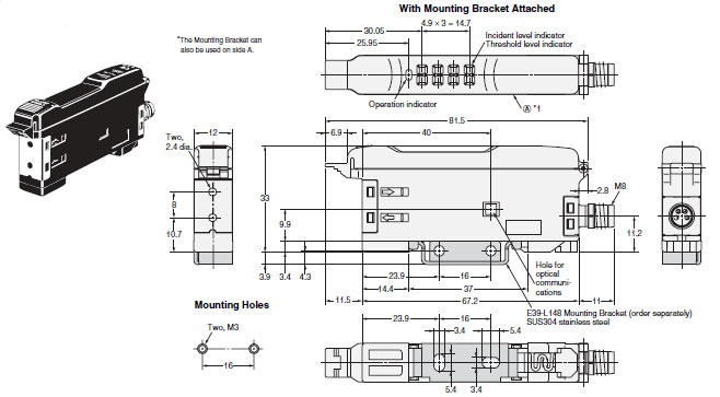
Pre-wired Amplifiers
E3X-DA11-N, E3X-DAG11-N, E3X-DA21-N E3X-DAH11-N, E3X-DAB11-N, E3X-DAB41-N
E3X-DA41-N, E3X-DAG41-N, E3X-DA51-N E3X-DAH41-N, E3X-DA11D
Note:The Mounting Bracket can also be used on side A.
Note:E3X-DA11-N/DA41-N/DAB11-N: 4-dia. vinyl-insulated round cable with 3 conductors (Conductor cross section: 0.2 mm2; Insulationdiameter: 1.1 mm).
Standard length: 2 m.
E3X-DA21-N/DA51-N: 4-dia. vinyl-insulated round cable with 4 conductors (Conductor cross section: 0.2 mm2; Insulation diameter:1.1 mm).
Standard length: 2 m.
Note:When using E39-L143 Mounting Brackets, there will be small gaps between the Amplifier Units if they are mounted side by side.
Pre-wired Amplifiers, Water-resistant Models
E3X-DA11V
E3X-DA41V
Note:The Mounting Bracket can also be used on side A.
Note:4-dia. vinyl-insulated round cable with 3 conductors (Conductor cross section: 0.2 mm2; Insulation diameter: 1.1 mm).
Standard length: 2 m.
Pre-wired Amplifiers, Twin-output Models
E3X-DA11TW
E3X-DA41TW
Note:The Mounting Bracket can also be used on side A.
Note:4-dia. vinyl-insulated round cable with 4 conductors (Conductor cross section: 0.2 mm2; Insulation diameter: 1.1 mm).
Standard length: 2 m.
Note:When using E39-L143 Mounting Brackets, there will be small gaps between the Amplifier Units if they are mounted side by side.
Amplifiers with Standard Connectors
E3X-DA6, E3X-DAG6, E3X-DA7, E3X-DAH6
E3X-DA8, E3X-DAB8, E3X-DA9, E3X-DAG8
E3X-DAB6, E3X-DAH8, E3X-DA6D, E3X-DA6-P
Amplifiers with M8 Connectors, Water-resistant Models
E3X-DA14V
E3X-DA44V
Amplifiers with Standard Connectors, Twin-output Models
E3X-DA6TW
E3X-DA8TW
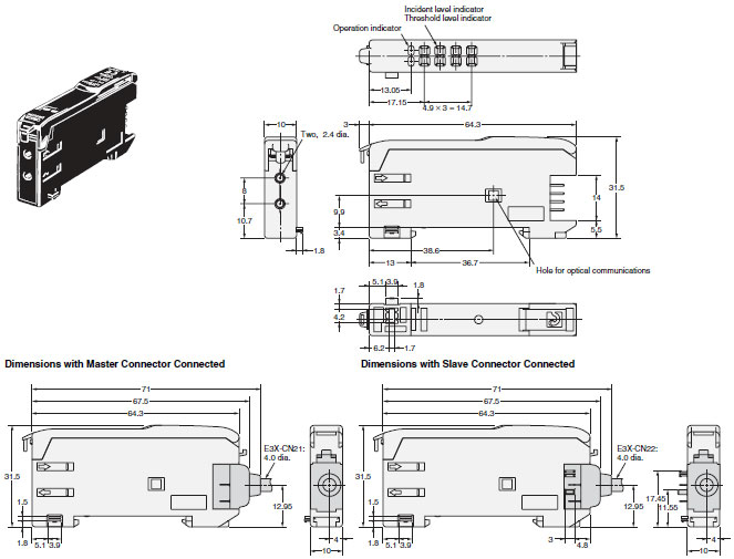
Amplifiers with Connectors
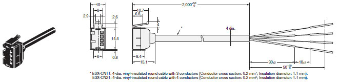
Master Connectors
E3X-CN11
E3X-CN21
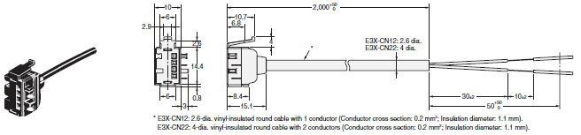
Slave Connectors
E3X-CN12
E3X-CN22
Mobile Console
E3X-MC11
last update: September 24, 2012
- NO. E3X-DA-N
- TYPE:Fiber Sensors Fiber Amplifier
 Copyright Statement
 - DATE:2021-06-07
- Associated products:
E3X-DA-S / MDA Digital Fiber Amplifier Unit/Features E3NW Sensor Communications Unit/Features