
OMRON E2C / E2C-HSensors/ Proximity Sensors/Separate Amplifier
OMRON E2C / E2C-H Sensors
- E2C / E2C-H Separate Amplifier Proximity Sensor with Adjustment Potentiometer/Lineup
- E2C / E2C-H Separate Amplifier Proximity Sensor with Adjustment Potentiometer/Dimensions
- E2C / E2C-H Separate Amplifier Proximity Sensor with Adjustment Potentiometer/Specifications
- E2C / E2C-H Separate Amplifier Proximity Sensor with Adjustment Potentiometer/Catalog
- Purchase the OMRON E2C / E2C-H Separate Amplifier
OMRON E2C / E2C-H Dimensions
/Images/l_464-25-118689-198x198.jpglast update: April 21, 2017
• Compact design with smaller Sensor Head.
• Heat-resistance model available for application between −10 and 200°C.
last update: April 21, 2017
Purchase the OMRON Separate Amplifier Please fill in the following
If you have just landed here, this product OMRON E2C / E2C-H Sensors,Sensors is offered online by Tianin FLD Technical Co.,Ltd. This is an online store providing Sensors at wholesale prices for consumers. You can call us or send enquiry, we would give you the prices, packing,deliverty and more detailed information on the E2C / E2C-H We cooperate with DHL,TNT,FEDEX,UPS,EMS,etc.They guarantee to meet your needs in terms of time and money,even if you need your OMRON E2C / E2C-HSensors tomorrow morning (aka overnight or next day air) on your desk, 2, 3 days or more.Note to international customers, YES, we ship worldwide.
NS-NSRCL1 / 3 / 10 Machine Monitoring Software NS-Runtime/Features
CJ1W-NC[][]4 CJ-series Position Control Units (High-Speed type)/Features
E6F-C Incremental 60-mm-dia. Rotary Encoder/Features
61F-GP-N2 Conductive Level Controller/Features
G9SA-300-SC Safety Relay Unit (Sensor Connector Type)/Features
OMRON E2C / E2C-H lineup
E2C / E2C-H Separate Amplifier Proximity Sensor with Adjustment Potentiometer/Lineuplast update: December 13, 2012
Sensors
Standard Models
| Sensor | Amplifier Units | ||||||
|---|---|---|---|---|---|---|---|
| Appearance | Stable sensing area *1 | Model | Model | Power supply/ Output | Timer function | Self- diagnostic output | |
 | 3.5 dia. | 0.8 (1.8) mm | E2C-CR8A 3M | E2C-GE4A | DC/(NPN) | --- | --- |
| E2C-GF4A | DC/(PNP) | --- | --- | ||||
| E2C-JC4AP 2M *2 | DC/(NPN) | Yes | Yes | ||||
| E2C-JC4A 2M | DC/(NPN) | Yes | --- | ||||
| E2C-AM4A | DC/(NPN, PNP) | --- | --- | ||||
| E2C-AK4A | AC | --- | --- | ||||
| 3.8 dia. | 0.8 (1.8) mm | E2C-CR8B 3M | E2C-GE4A | DC/(NPN) | --- | --- | |
| E2C-GF4A | DC/(PNP) | --- | --- | ||||
| E2C-JC4AP 2M *2 | DC/(NPN) | Yes | Yes | ||||
| E2C-JC4A 2M | DC/(NPN) | Yes | --- | ||||
| E2C-AM4A | DC/(NPN, PNP) | --- | --- | ||||
| E2C-AK4A | AC | --- | --- | ||||
| M5 | 1 (2) mm | E2C-X1A 3M | E2C-GE4A | DC/(NPN) | --- | --- | |
| E2C-GF4A | DC/(PNP) | --- | --- | ||||
| E2C-JC4AP 2M *2 | DC/(NPN) | Yes | Yes | ||||
| E2C-JC4A 2M | DC/(NPN) | Yes | --- | ||||
| E2C-AM4A | DC/(NPN, PNP) | --- | --- | ||||
| E2C-AK4A | AC | --- | --- | ||||
| 5.4 dia. | 1 (2) mm | E2C-C1A 3M | E2C-GE4A | DC/(NPN) | --- | --- | |
| E2C-GF4A | DC/(PNP) | --- | --- | ||||
| E2C-JC4AP 2M *2 | DC/(NPN) | Yes | Yes | ||||
| E2C-JC4A 2M | DC/(NPN) | Yes | --- | ||||
| E2C-AM4A | DC/(NPN, PNP) | --- | --- | ||||
| E2C-AK4A | AC | --- | --- | ||||
| M8 | 1.5 (3) mm | E2C-X1R5A 3M | E2C-GE4A | DC/(NPN) | --- | --- | |
| E2C-GF4A | DC/(PNP) | --- | --- | ||||
| E2C-JC4AP 2M *2 | DC/(NPN) | Yes | Yes | ||||
| E2C-JC4A 2M | DC/(NPN) | Yes | --- | ||||
| E2C-AM4A | DC/(NPN, PNP) | --- | --- | ||||
| E2C-AK4A | AC | --- | --- | ||||
| M12 | 2 (5) mm | E2C-X2A 3M | E2C-JC4AP 2M *2 | DC/(NPN) | Yes | Yes | |
| E2C-JC4A 2M | DC/(NPN) | Yes | --- | ||||
| E2C-AM4A | DC/(NPN, PNP) | --- | --- | ||||
| E2C-AK4A | AC | --- | --- | ||||
| M18 | 5 (10) mm | E2C-X5A 3M | E2C-AM4A | DC/(NPN, PNP) | --- | --- | |
| E2C-AK4A | AC | --- | --- | ||||
| M30 | 10 (18) mm | E2C-X10A 3M | E2C-AM4A | DC/(NPN, PNP) | --- | --- | |
| E2C-AK4A | AC | --- | --- | ||||
 | 40 dia. | 20 (50) mm | E2C-C20MA 3M | E2C-AM4A | DC/(NPN, PNP) | --- | --- |
| E2C-AK4A | AC | --- | --- | ||||
*1. Values in parentheses are for the maximum sensing distances at 23°C.
*2. Self-diagnostic output, timer, and DIN Track mounting.
Heat-resistant Model
| Sensor | Amplifier Unit | |||
|---|---|---|---|---|
| Appearance | Stable sensing area | Model | Model | |
 | M8 | 1.5 mm | E2C-X1R5AH 3M | E2C-JC4CH 2M |
| M12 | 2 mm | E2C-X2AH 3M | E2C-JC4DH 2M | |
| M18 | 5 mm | E2C-X5AH 3M | E2C-JC4EH 2M | |
Note: Characteristics will change if the cable length changes. Do not cut or extend the cable.
Accessories (Order Separately)
Mounting Brackets
A Mounting Bracket is not provided with the Sensor. Order a Mounting Bracket separately if required.
| Name | Model | Applicable Sensors | Remarks |
|---|---|---|---|
| Mounting Brackets | Y92E-F3R5 | E2C-CR8A, for 3.5 dia. | --- |
| Y92E-F5R4 | E2C-C1A, for 5.4 dia. |
Connection Sockets
A Socket is not provided with the Amplifier Unit. Order a Socket separately if required.
| Name | Model | Applicable Amplifier Unit | Remarks |
|---|---|---|---|
| Front Connection Sockets | PYF08A | E2C-GE4A E2C-GF4A | Hold-down Clips (Order Separately) PYC-A1 Sold as a set. |
| P2CF-08 | E2C-AM4A | --- | |
| P2CF-11 | E2C-AK4A | ||
| Back Connection Sockets | P3G-08 | E2C-AM4A | |
| P3GA-11 | E2C-AK4A | ||
| PY08 | E2C-GE4A E2C-GF4A |
Adapters
An Adapter is not provided with the Amplifier Unit. Order an Adapter separately if required.
| Name | Model | Applicable Amplifier Unit | Remarks |
|---|---|---|---|
| Embedded Adapters | Y92F-30 | E2C-AM4A/-AK4A | --- |
| Y92F-70 | |||
| Y92F-71 |
For details on Mounting Brackets, Protective Covers, and Sputter Protective Covers, refer to Accessories on Y92[].
last update: December 13, 2012
OMRON E2C / E2C-H dimension
E2C / E2C-H Separate Amplifier Proximity Sensor with Adjustment Potentiometer/Dimensionslast update: February 7, 2019
(Unit: mm)
Tolerance class IT16 applies to dimensions in this data sheet unless otherwise specified.
Main Units
Sensor
E2C-CR8A/-CR8B

E2C-X1A

E2C-C1A

E2C-X1R5A
E2C-X1R5AH *
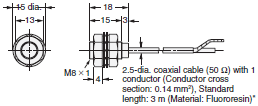
E2C-X2A
E2C-X2AH *
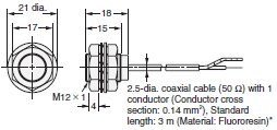
E2C-X5A
E2C-X5AH *
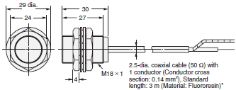
E2C-X10A
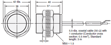
E2C-C20MA

Mounting Hole Dimensions

Amplifier Units
E2C-GE4A
E2C-GF4A

E2C-AK4A (11-pin)
E2C-AM4A (8-pin)

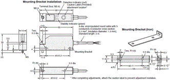
E2C-JC4A
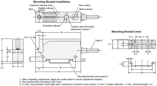
E2C-JC4AP
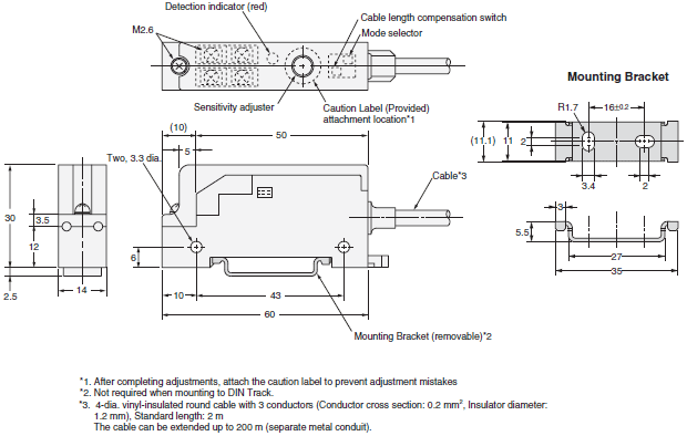
E2C-JC4[]H
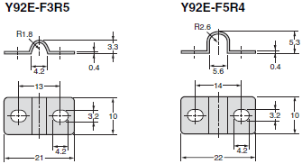
Accessories (Order Separately)
Mounting Bracket
Mounting Bracket (for Unthreaded Cylindrical Models)
Y92E-F3R5 (for 3.5 dia.)
Y92E-F5R4 (for 5.4 dia.)
Front Connection Sockets
PYF08A
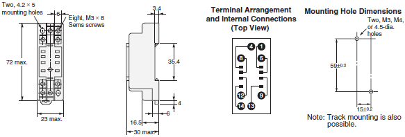
P2CF-08

P2CF-11

Back Connection Sockets
P3G-08

P3GA-11

PY08

Embedded Mounting Adapter (for E2C-AK4A/E2C-AM4A Amplifier Unit)
Y92F-30
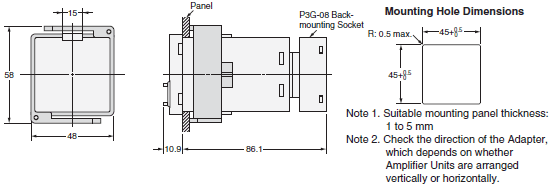
Y92F-70
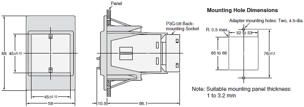
Y92F-71

last update: February 7, 2019
OMRON E2C / E2C-H specification
E2C / E2C-H Separate Amplifier Proximity Sensor with Adjustment Potentiometer/Specificationslast update: August 17, 2015
Standard Models
Sensors
| Model | E2C-CR8A/ -CR8B | E2C-X1A/ -C1A | E2C-X1R5A | E2C-X2A | E2C-X5A | E2C-X10A | E2C-C20MA | |
|---|---|---|---|---|---|---|---|---|
| Sensing distance (at 23°C) | 1.8 mm | 2 mm | 3 mm | 5 mm | 10 mm | 18 mm | 50 mm | |
| Stable sensing area | Ambient temperature | 0 to 0.8 mm | 0 to 1 mm | 0 to 1.5 mm | 0 to 2 mm | 0 to 5 mm | 0 to 10 mm | 0 to 20 mm |
| At 0 to 40°C | 0 to 1.2 mm | 0 to 1.5 mm | 0 to 2 mm | 0 to 2.5 mm | 0 to 7 mm | 0 to 15 mm | 0 to 28 mm | |
| Differential travel | Refer to the amplifier unit specifications below. | |||||||
| Detectable object | Ferrous metal (The sensing distance decreases with non-ferrous metal. Refer to Data Sheet.) | |||||||
| Standard sensing object | Iron, 5 × 5 × 1 mm | Iron, 8 × 8 × 1 mm | Iron, 12 × 12 × 1 mm | Iron, 18 × 18 × 1 mm | Iron, 30 × 30 × 1 mm | Iron, 50 × 50 × 1 mm | ||
| Response frequency *1 | 1 kHz | 800 Hz | 350 Hz | 100 Hz | 50 Hz | |||
| Ambient temperature range | Operating/Storage: -25 to 70°C (with no icing or condensation) | |||||||
| Ambient humidity range | Operating/Storage: 35% to 95% (with no condensation) | |||||||
| Temperature influence | 15% max. of sensing distance at 23°C in the temperature range of -25 to 70°C | |||||||
| Vibration resistance | Destruction: 10 to 55 Hz, 1.5-mm double amplitude for 2 hours each in X and Y directions | |||||||
| Shock resistance | Destruction: 500 m/s2 3 times each in X and Y directions | |||||||
| Degree of protection | IEC 60529 IP67, in-house standards: oil-resistant | |||||||
| Connection method *2 | Pre-wired Models | |||||||
| High-frequency coaxial cable (Standard cable length: 3 m) | ||||||||
| Weight (packed state) | Approx. 40 g | Approx. 45 g | Approx. 50 g | Approx. 60 g | Approx. 140 g | Approx. 270 g | Approx. 300 g | |
| Materials | Case | Stainless steel | Brass | |||||
| Sensing surface | ABS resin | |||||||
| Cable | Polyethylene | |||||||
| Clamping nut | --- | Brass, nickel-plated (except E2C-C1A) | ||||||
| Toothed washer | --- | Brass, zinc-plated (except E2C-C1A) | ||||||
| Accessories | --- | |||||||
*1. The minimum value when using the solid-state control output on the Amplifier Unit.
Measurement conditions are as follows: standard sensing object, a distance of twice the standard sensing object,
and a set distance of half the sensing distance.
*2. Refer to 6 for cable lengths when combining Amplifier Units and Sensors.
The characteristic impedance of the high-frequency coaxial cable is 50 Ω.
Amplifier Units
| Model | E2C-GE4A | E2C-GF4A | E2C-JC4A E2C-JC4AP | E2C-AM4A | E2C-AK4A | |
|---|---|---|---|---|---|---|
| Power supply voltage (operating voltage range) | 12 to 24 VDC (10 to 30 VDC), ripple (p-p): 10% max. *1 | 100 to 240 VAC (90 to 264 VAC) 50/60 Hz | ||||
| Current consumption | 25 mA max. | 45 mA max. | 50 mA max. | 55 mA max. | ||
| Sensing distance adjustment range *2 | 20% min. of rated sensing distance with 4-turn potentiometer | 20% to 100% of rated sensing distance with 4-turn potentiometer | ||||
| Differential travel adjustment range | Differential travel fixed (10% max. of sensing distance) | 1% to 5% of rated sensing distance | ||||
| Response time | Solid- state | (Refer to the response frequency of the Proximity Sensor.) | ||||
| Relay | --- | 20 ms max. | ||||
| Control outputs | Solid- state | NPN Load resistance: 4.7 kΩ, 100 mA max. (30 VDC max.) (Residual voltage: 1.5 V max.) | PNP Load resistance: 4.7 kΩ, 100 mA max. (30 VDC max.) (Residual voltage: 1.5 V max.) | NPN Open-collector output 100 mA max. (30 VDC max.) (Residual voltage: 0.7 V max.) (E2C-JC4AP: 1 V max.) | NPN/PNP output Open-collector output 200 mA max. (30 VDC max.) (Residual voltage: 1.5 V max.) | Transistor/ photocoupler 50 mA max. (40 VDC max.) (Residual voltage: 2 V max.) |
| Relay | --- | Relay output, SPDT 2 A at 250 VAC, cosφ = 1 (resistive load) *3 | ||||
| Indicators | Detection indicator (red) (OPERATION) | Detection indicator (red) (OPERATION) Stability indicator (green) (STABILITY) | Detection indicator (red) (OPERATION) Stability indicator (green) (STABILITY) | |||
| Operation mode | Changed with NO/NC switch. | |||||
| Self-diagnostic output | --- | (E2C-JC4AP only) Output transistor turns ON when Sensor open circuit or unstable sensing is detected; solid-state NPN open-collector 50 mA max. (30 VDC max.) (Residual voltage: 1 V max.) | --- | |||
| Timer function | --- | OFF-delay: 40 ±10 ms | --- | |||
| Cable length compensation between Sensor and Amplifier Unit | --- | (E2C-JC4AP only) 3 m/5 m, terminals Short-plate switching Shorted: 1 to 3 m Open: 3 to 5 m | Mode switched with 4-position switch. | |||
| Ambient temperature range | Operating/storage: -10 to 55°C (with no icing or condensation) | |||||
| Ambient humidity range | Operating/Storage: 35% to 85% (E2C-JC4AP: 35% to 95%) (with no condensation) | |||||
| Temperature influence | 10% max. of sensing distance at 23°C in the temperature range of -10 to 55°C | |||||
| Voltage influence | DC Models: ±1% max. of sensing distance at rated voltage in the rated voltage ±20% range AC Models: ±1% max. of sensing distance at rated voltage in the rated voltage ±10% range | |||||
| Insulation resistance | 50 MΩ min. (at 500 VDC) between current-carrying parts and case | |||||
| Dielectric strength | DC Models: 1,000 VAC, 50/60 Hz for 1 min between current-carrying parts and case AC Models: 1,500 VAC, 50/60 Hz for 1 min between current-carrying parts and case | |||||
| Vibration resistance | Destruction: 10 to 25 Hz, 2-mm double amplitude for 2 hours each in X, Y, and Z directions | Destruction: 10 to 55 Hz, 1.5-mm double amplitude for 2 hours each in X, Y, and Z directions | Destruction: 10 to 25 Hz, 2-mm double amplitude for 2 hours each in X, Y, and Z directions | |||
| Shock resistance | Destruction: 100 m/s2 3 times each in X, Y, and Z directions | |||||
| Life expectancy | --- | Mechanical: 10,000,000 operations min. Electrical: 100,000 operations min. | ||||
| Connection method | Terminal block | Pre-wired Models (Standard cable length: 2 m) | Terminal block | |||
| Weight (packed state) *4 | Approx. 20 g | E2C-JC4A: Approx. 50 g E2C-JC4AP: Approx 80 g | Approx. 140 g | Approx. 250 g | ||
| Accessories | Instruction manual | Caution labels, Mounting Bracket (E2C-JC4A: M3 × 15 Phillips mounting screw), instruction manual | Instruction manual | |||
*1. A full-wave rectification power supply of 24 VDC ±10% (average value) can be used (except for the E2C-GE4[]).
*2. The sensing distance range required to maintain performed is given for using the Amplifier Unit in combination with
the Sensor.
*3. Internal relay: G2R-14 DC 12V
*4. The weight of the Connection Socket is not included.
Heat-resistant Models
Sensors
| Model | E2C-X1R5AH | E2C-X2AH | E2C-X5AH | |
|---|---|---|---|---|
| Detectable object | Ferrous metal (The sensing distance decreases with non-ferrous metal, refer to Datasheet.) | |||
| Standard sensing object | Iron, 8 × 8 × 1 mm | Iron, 12 × 12 × 1 mm | Iron, 18 × 18 × 1 mm | |
| Stable sensing area | 0 to 1.5 mm | 0 to 2 mm | 0 to 5 mm | |
| Differential travel | 0.04 mm max. | 0.1 mm max. | ||
| Response frequency *1 | 300 Hz | |||
| Ambient temperature range | Operating/Storage: -10 to 200°C (with no icing or condensation) | |||
| Ambient humidity range | Operating/Storage: 35% to 95% (with no condensation) | |||
| Temperature influence | ±0.2%/°C | |||
| Vibration resistance | Destruction: 10 to 55 Hz, 1.5-mm double amplitude for 2 hours each in X, Y, and Z directions | |||
| Shock resistance | Destruction: 500 m/s2 3 times each in X, Y, and Z directions | |||
| Degree of protection | IEC 60529 IP60 *2 | |||
| Connection method | Pre-wired Models (Cable length: 3 m) Heat-resistant, high-frequency coaxial cable | |||
| Weight (packed state) | Approx. 50 g | Approx. 60 g | Approx. 140 g | |
| Materials | Case | Brass | ||
| Sensing surface | PEEK (polyether ether ketone) | |||
| Cable | Fluorine resin | |||
| Clamping nut | Brass, nickel-plated | |||
| Toothed washer | Iron, zinc-plated | |||
Note: Ratings and characteristic are given for 50% of the stable sensing area.
*1. Measurement conditions are as follows: standard sensing object, a distance of twice the standard sensing object,
and a set distance of half the sensing distance.
*2. Do not operate the Sensor in areas exposed to water vapor because the enclosure is not waterproof.
Amplifier Units
| Model | E2C-JC4CH | E2C-JC4DH | E2C-JC4EH | |
|---|---|---|---|---|
| Power supply voltage *1 (operating voltage range) | 12 to 24 VDC (10 to 30 VDC), ripple (p-p): 10% max. | |||
| Current consumption | 45 mA max. | |||
| Sensing distance adjustment range *2 | 20% to 100% of rated sensing distance 4-turn potentiometer | |||
| Control outputs | Load current | NPN open collector, 100 mA max. (30 VDC max.) | ||
| Residual voltage | 0.8 V max. | |||
| Indicators | Detection indicator (red) | |||
| Operation mode | Changed with NO/NC switch. | |||
| Cable length compensation | Switched between 3 and 5 m. | |||
| Ambient temperature range | Operating/storage: -10 to 55°C (with no icing or condensation) | |||
| Ambient humidity range | Operating/storage: 35% to 85% (with no condensation) | |||
| Temperature influence | ±0.08%/°C | |||
| Voltage influence | ±2% max. of sensing distance at rated voltage in the rated voltage ±20% range | |||
| Insulation resistance | 50 MΩ min. (at 500 VDC) between current-carrying parts and case | |||
| Dielectric strength | 1,000 VAC, 50/60 Hz for 1 min between current-carrying parts and case | |||
| Vibration resistance | Destruction: 10 to 55 Hz, 1.5-mm double amplitude for 2 hours each in X, Y, and Z directions | |||
| Shock resistance | Destruction: 100 m/s2 3 times each in X, Y, and Z directions | |||
| Degree of protection | IEC 60529 IP20 | |||
| Connection method | Pre-wired Models (Cable length: 2 m) | |||
| Weight (packed state) | Approx. 80 g | |||
| Accessories | Caution labels, Mounting Bracket, instruction manual | |||
*1. A full-wave rectification power supply of 24 VDC ±10% (average value) can be used.
*2. The sensing distance range required to maintain performed is given for using the Amplifier Unit in combination with
the Sensor.
last update: August 17, 2015
OMRON E2C / E2C-H catalog
E2C / E2C-H Separate Amplifier Proximity Sensor with Adjustment Potentiometer/Catalog- Catalog
- Manual
- CAD
English
Global Edition
| Catalog Name | Catalog Number [size] | Last Update | |
|---|---|---|---|
| | - [1718KB] | Feb 07, 201920190207 | E2C, E2C-H Data Sheet |
- NO. E2C / E2C-H
- TYPE:Proximity Sensors Separate Amplifier
 Copyright Statement
 - DATE:2021-06-09
- Associated products:
E2C-EDA High Precision Positioning Inductive Proximity Sensor/Features E2K-C Long-distance type/Features