OMRON MYRelays/ General Purpose Relays/For Control Panel
OMRON MY Relays
OMRON MY Dimensions
/Images/l_948-25-118986-198x198.jpglast update: June 11, 2018
• In addition to our standard type (MY), an abundant lineup of models including latching relays that retain contact operation status (MYK) and sealed relays suitable for environments where dust and corrosive gases are present (MYQ/MYH) are also available.
• Selection is possible to suit the application, such as models with operation indicators and models with latching levers (MY plug-in terminals).
• Wiring work can be shortened by as much as 60%* compared to conventional screw terminal sockets by combining with push-in plus terminal sockets (PYF-[]-PU) that feature light insertion force and strong pull-out strength to achieve less wiring work.
*When both push-in plus terminals and screw terminal sockets are combined with plug-in terminal types (according to actual OMRON measurements as of November 2015)
last update: June 11, 2018
Purchase the OMRON For Control Panel Please fill in the following
If you have just landed here, this product OMRON MY Relays,Relays is offered online by Tianin FLD Technical Co.,Ltd. This is an online store providing Relays at wholesale prices for consumers. You can call us or send enquiry, we would give you the prices, packing,deliverty and more detailed information on the MY We cooperate with DHL,TNT,FEDEX,UPS,EMS,etc.They guarantee to meet your needs in terms of time and money,even if you need your OMRON MYRelays tomorrow morning (aka overnight or next day air) on your desk, 2, 3 days or more.Note to international customers, YES, we ship worldwide.
UM, MC3 Safety Mat/Safety Mat Controller/Features
NT20, NT31(C)-EV3, NT631C-EV3 Programmable Terminals/Features
M2P Indicators/Features
E5C2 Temperature Controller/Features
NX-TS NX-series Temperature Input Unit/Features
OMRON MY lineup
MY Miniature Power Relays/Lineuplast update: November 1, 2018
Model List
Miniature Power Relays: MY
| Classification | Number of poles | Contacts | Plug-in terminals | PCB terminals  | Case-surface mounting  | ||
|---|---|---|---|---|---|---|---|
| With operation indicator | |||||||
| With latching lever | |||||||
| Standard models (compliant with Electrical Appliances and Material Safety Act) | 2 | Single | MY2 | MY2N | MY2IN(S) | MY2-02 | MY2F |
| Bifurcated | MY2Z | MY2ZN | |||||
| 3 | Single | MY3 | MY3N | MY3-02 | MY3F | ||
| 4 | Single | MY4 | MY4N | MY4IN(S) | MY4-02 | MY4F | |
| Bifurcated | MY4Z | MY4ZN | MY4ZIN(S) | MY4Z-02 | MY4ZF | ||
| Crossbar bifurcated | MY4Z-CBG | MY4ZN-CBG | |||||
| Models with built-in diode for coil surge absorption (compliant with Electrical Appliances and Material Safety Act) | 2 | Single | MY2-D | MY2N-D2 | MY2IN-D2(S) | ||
| Bifurcated | MY2Z-D | MY2ZN-D2 | |||||
| 3 | Single | MY3-D | MY3N-D2 | ||||
| 4 | Single | MY4-D | MY4N-D2 | MY4IN-D2(S) | |||
| Bifurcated | MY4Z-D | MY4ZN-D2 | MY4ZIN-D2(S) | ||||
| Models with built-in CR circuit for coil surge absorption (compliant with Electrical Appliances and Material Safety Act) | 2 | Single | MY2-CR | MY2N-CR | |||
| Bifurcated | MY2Z-CR | MY2ZN-CR | |||||
| 4 | Single | MY4-CR | MY4N-CR | MY4IN-CR(S) | |||
| Bifurcated | MY4Z-CR | MY4ZN-CR | MY4ZIN-CR(S) | ||||
Note:1. The models in this table are UL/CSA certified. This is indicated with a certification mark on the products. (Except
crossbar bifurcated models MY4Z-CBG and MY4Z-CBG)
2. The standard models with plug-in terminals, models with built-in diodes for coil surge absorption, and models with
built-in CR circuits for coil surge absorption were used in combination with the PYF[]A-E, PYF[]-S and PYF-[]-PU for
the EC Declaration of Conformity. These products display the CE Marking.
Miniature Power Latching Relays (MYK)
| Classification | Number of poles | Contacts | Plug-in terminals | PCB terminals | |
|---|---|---|---|---|---|
| With operation indicator | |||||
| Standard models | 2 | Single | MY2K | MY2K-02 | |
Miniature Power Sealed Relays (MYQ/MYH)
| Classification | Number of poles | Contacts | Plug-in terminals | PCB terminals | |
|---|---|---|---|---|---|
| With operation indicator | |||||
| Plastic Sealed Relays | 4 | Single | MYQ4 | MYQ4N | MYQ4-02 |
| Bifurcated | MYQ4Z | MYQ4Z-02 | |||
| Hermetically Sealed Relays | 4 | Single | MY4H | MY4H-0 | |
| Bifurcated | MY4ZH | MY4ZH-0 | |||
Refer to Front-connecting Sockets and Back-connecting Sockets in Common Options (Order Separately) for main unit and socket combinations.
Ordering Information
When your order, specify the rated voltage.
MY Miniature Power Relays
Plug-in Terminals
Without operation indicator
| Classification | Number of poles | Contacts | Model | Rated voltage |
|---|---|---|---|---|
| Standard models (compliant with Electrical Appliances and Material Safety Act) | 2 | Single | MY2 | 12, 24, 100/110, 110/120, 200/220, 220/240 VAC |
| 12, 24, 48, 100/110 VDC | ||||
| Bifurcated | MY2Z | 12, 24, 100/110, 110/120, 200/220, 220/240 VAC | ||
| 12, 24, 48, 100/110 VDC | ||||
| 3 | Single | MY3 | 12, 24, 100/110, 110/120, 200/220, 220/240 VAC | |
| 12, 24, 48, 100/110 VDC | ||||
| 4 | Single | MY4 | 12, 24, 100/110, 110/120, 200/220, 220/240 VAC | |
| 12, 24, 48, 100/110 VDC | ||||
| Bifurcated | MY4Z | 100/110, 110/120, 200/220, 220/240 VAC | ||
| 12, 24, 48, 100/110 VDC | ||||
| Crossbar bifurcated | MY4Z-CBG | 100/110, 110/120, 200/220 VAC | ||
| 12, 24, 48, 100/110 VDC | ||||
| Models with built-in diode for coil surge absorption (DC coil specification only) | 2 | Single | MY2-D | 12, 24, 48, 100/110 VDC |
| Bifurcated | MY2Z-D | 12, 24, 100/110 VDC | ||
| 3 | Single | MY3-D | 12, 24, 100/110 VDC | |
| 4 | Single | MY4-D | 12, 24, 48, 100/110 VDC | |
| Bifurcated | MY4Z-D | 12, 24, 48, 100/110 VDC | ||
| Models with built-in CR circuit for coil surge absorption (AC coil specification only) | 2 | Single | MY2-CR | 100/110, 110/120, 200/220, 220/240 VAC |
| Bifurcated | MY2Z-CR | 100/110, 200/220 VAC, | ||
| 4 | Single | MY4-CR | 100/110, 110/120, 200/220, 220/240 VAC | |
| Bifurcated | MY4Z-CR | 100/110, 110/120, 200/220, 220/240 VAC |
With operation indicator
| Classification | Number of poles | Contacts | Model | Rated voltage |
|---|---|---|---|---|
| Standard models (compliant with Electrical Appliances and Material Safety Act) | 2 | Single | MY2N | 12, 24, 100/110, 110/120, 200/220, 220/240 VAC |
| 12, 24, 48, 100/110 VDC | ||||
| Bifurcated | MY2ZN | 12, 24, 100/110, 110/120, 200/220, 220/240 VAC | ||
| 12, 24, 48, 100/110 VDC | ||||
| 3 | Single | MY3N | 12, 24, 100/110, 110/120, 200/220, 220/240 VAC | |
| 12, 24, 48, 100/110 VDC | ||||
| 4 | Single | MY4N | 12, 24, 100/110, 110/120, 200/220, 220/240 VAC | |
| 12, 24, 48, 100/110 VDC | ||||
| Bifurcated | MY4ZN | 24, 100/110, 110/120, 200/220, 220/240 VAC | ||
| 12, 24, 48, 100/110 VDC | ||||
| Crossbar bifurcated | MY4ZN-CBG | 100/110, 200/220 VAC | ||
| 24 VDC | ||||
| Models with built-in diode for coil surge absorption (DC coil specification only) | 2 | Single | MY2N-D2 | 12, 24, 48, 100/110 VDC |
| Bifurcated | MY2ZN-D2 | 12, 24, 100/110 VDC | ||
| 3 | Single | MY3N-D2 | 12, 24, 100/110 VDC | |
| 4 | Single | MY4N-D2 | 12, 24, 48, 100/110 VDC | |
| Bifurcated | MY4ZN-D2 | 12, 24, 48, 100/110 VDC | ||
| Models with built-in CR circuit for coil surge absorption (AC coil specification only) | 2 | Single | MY2N-CR | 100/110, 110/120, 200/220, 220/240 VAC |
| 4 | Single | MY4N-CR | 100/110, 110/120, 200/220, 220/240 VAC | |
| Bifurcated | MY4ZN-CR | 100/110, 110/120, 200/220, 220/240 VAC |
With operation indicator/latching lever
| Classification | Number of poles | Contacts | Model | Rated voltage |
|---|---|---|---|---|
| Standard models (compliant with Electrical Appliances and Material Safety Act) | 2 | Single | MY2IN(S) | 100/110, 200/220 VAC |
| 12, 24, 48 VDC | ||||
| 4 | Single | MY4IN(S) | 100/110, 200/220 VAC | |
| 12, 24, 48 VDC | ||||
| Bifurcated | MY4ZIN(S) | 100/110, 200/220 VAC | ||
| 12, 24, 48 VDC | ||||
| Models with built-in diode for coil surge absorption (DC coil specification only) | 2 | Single | MY2IN-D2(S) | 12, 24, 48 VDC |
| 4 | Single | MY4IN-D2(S) | 12, 24, 48 VDC | |
| Bifurcated | MY4ZIN-D2(S) | 12, 24, 48 VDC | ||
| Models with built-in CR circuit for coil surge absorption (AC coil specification only) | 4 | Single | MY4IN-CR(S) | 100/110, 200/220 VAC |
| Bifurcated | MY4ZIN-CR(S) | 100/110, 200/220 VAC |
PCB terminals
| Classification | Number of poles | Contacts | Model | Rated voltage |
|---|---|---|---|---|
| Standard models (compliant with Electrical Appliances and Material Safety Act) | 2 | Single | MY2-02 | 12, 24, 100/110, 110/120, 200/220, 220/240 VAC |
| 12, 24, 48, 100/110 VDC | ||||
| 3 | Single | MY3-02 | 12, 24, 100/110, 110/120, 200/220, 220/240 VAC | |
| 12, 24, 48, 100/110 VDC | ||||
| 4 | Single | MY4-02 | 12, 24, 100/110, 110/120, 200/220, 220/240 VAC | |
| 12, 24, 48, 100/110 VDC | ||||
| Bifurcated | MY4Z-02 | 100/110, 110/120, 200/220 VAC | ||
| 12, 24, 48, 100/110 VDC |
Case-surface mounting
| Classification | Number of poles | Contacts | Model | Rated voltage |
|---|---|---|---|---|
| Standard models (compliant with Electrical Appliances and Material Safety Act) | 2 | Single | MY2F | 24, 100/110, 110/120, 200/220, 220/240 VAC |
| 12, 24, 48, 100/110 VDC | ||||
| 3 | Single | MY3F | 24, 100/110, 200/220 VAC | |
| 24, 100/110 VDC | ||||
| 4 | Single | MY4F | 24, 100/110, 110/120, 200/220 VAC | |
| 12, 24, 48, 100/110 VDC | ||||
| Bifurcated | MY4ZF | 200/220 VAC | ||
| 12, 24 VDC |
MYK Miniature Power Latching Relays
Main unit
Plug-in terminals
| Classification | Number of poles | Contacts | Model | Rated voltage |
|---|---|---|---|---|
| Standard models (compliant with Electrical Appliances and Material Safety Act) | 2 | Single | MY2K | 12, 24, 100, 100/110 VAC |
| 12, 24, 48 VDC |
PCB terminals
| Classification | Number of poles | Contacts | Model | Rated voltage |
|---|---|---|---|---|
| Standard models (compliant with Electrical Appliances and Material Safety Act) | 2 | Single | MY2K-02 | 24, 100 VAC |
| 12, 24 VDC |
MYQ/MYH Miniature Power Sealed Relays
Plastic Sealed Relays
Plug-in terminals
| Classification | Number of poles | Contacts | With operation indicator | |||
|---|---|---|---|---|---|---|
| Model | Rated voltage | Model | Rated voltage | |||
| Standard models (compliant with Electrical Appliances and Material Safety Act) | 4 | Single | MYQ4 | 100/110, 110/120, 200/220, 220/240 VAC | MYQ4N | 24, 100/110, 110/120, 200/220, 220/240 VAC |
| 24 VDC | 12, 24, 48, 100/110 VDC | |||||
| Bifurcated | MYQ4Z | 100/110, 110/120, 200/220 VAC | ||||
| 12, 24 VDC | ||||||
PCB terminals
| Classification | Number of poles | Contacts | Model | Rated voltage |
|---|---|---|---|---|
| Standard models (compliant with Electrical Appliances and Material Safety Act) | 4 | Single | MYQ4-02 | 50, 200/220, 220/240 VAC |
| 24 VDC | ||||
| Bifurcated | MYQ4Z-02 | 100/110 VAC | ||
| 24, 48 VDC |
Hermetically Sealed Relays
Plug-in terminals
| Classification | Number of poles | Contacts | Model | Rated voltage |
|---|---|---|---|---|
| Standard models (compliant with Electrical Appliances and Material Safety Act) | 4 | Single | MY4H | 24, 100/110, 110/120 VAC |
| 12, 24, 48, 100/110 VDC | ||||
| Bifurcated | MY4ZH | 24, 100/110, 110/120 VAC | ||
| 12, 24, 48, 100/110 VDC |
PCB terminals
| Classification | Number of poles | Contacts | Model | Rated voltage |
|---|---|---|---|---|
| Standard models (compliant with Electrical Appliances and Material Safety Act) | 4 | Single | MY4H-0 | 110/120 VAC |
| 24 VDC | ||||
| Bifurcated | MY4ZH-0 | 24, 100/110 VDC |
Common Options (Order Separately)
Front-mounting Sockets
| Number of pins | Applicable relay model *1 | Terminal Type | Mounting Method | Appearance | Model |
|---|---|---|---|---|---|
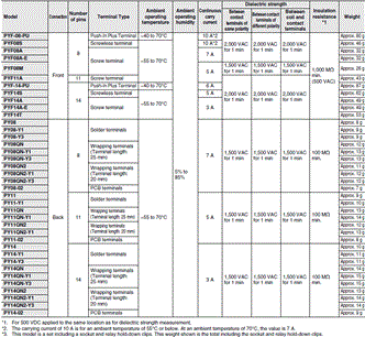
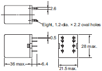
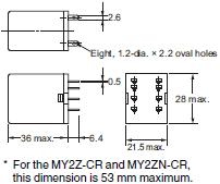
| 8 | MY2[] MY2IN(S) | Push-In Plus Terminal (Integrated socket with release lever) | Mounted on a DIN track or with screws*2 |  | PYF-08-PU |
| MY2Z[]-CR | Push-In Plus Terminal (Without release lever) | Mounted on a DIN track or with screws*2 |  | PYF-08-PU-L | |
| MY2[] MY2IN(S) MY2Z[]-CR | Screwless terminal | Mounted on a DIN track |  | PYF08S | |
| MY2[] MY2IN(S) MY2Z[]-CR | Screw terminal (M3 screw size) | Mounted on a DIN track or with screws |  | PYF08A | |
| MY2[] MY2IN(S) MY2Z[]-CR | Screw terminal Finger-protection structure*3 (M3 screw size) | Mounted on a DIN track or with screws |  | PYF08A-E | |
| MY2[] MY2IN(S) MY2Z[]-CR | Screw terminal (M3.5 screw size) | Screw mounting only |  | PYF08M | |
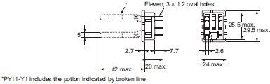
| 11 | MY3 | Screw terminal (M3 screw size) | Mounted on a DIN track or with screws |  | PYF11A |
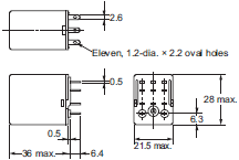
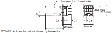
| 14 | MY4[], MY4H MYQ4[], MY4[](S) MY2K | Push-In Plus Terminal (Integrated socket with release lever) | Mounted on a DIN track or with screws*2 |  | PYF-14-PU |
| MY4Z[]-CBG-CR | Push-In Plus Terminal (Without release lever) | Mounted on a DIN track or with screws*2 |  | PYF-14-PU-L | |
| MY4[], MY4H MYQ4[], MY4[](S) MY2K MY4Z[]-CBG-CR | Screwless terminal | Mounted on a DIN track |  | PYF14S | |
| MY4[], MY4H MYQ4[], MY4[](S) MY2K MY4Z[]-CBG-CR | Screw terminal (M3 screw size) | Mounted on a DIN track or with screws |  | PYF14A | |
| MY4[], MY4H MYQ4[], MY4[](S) MY2K MY4Z[]-CBG-CR | Screw terminal Finger-protection structure*3 (M3 screw size) | Mounted on a DIN track or with screws |  | PYF14A-E | |
| Screw terminal (M3.5 screw size) | Mounted on a DIN track or with screws |  | PYF14T |
*1. The applicable relay model is a plug-in terminal type.
*2. There are screw mounting holes in the DIN hooks on the PYF-[][]-PU and P2RF-[][]-PU. Pull out the DIN hook tabs to
mount the Sockets with screws.
*3. The finger-protection type (PYF[]A-E) is a type in which the terminal cover is integrated into the socket. Round
terminals cannot be used. Use forked terminals or ferrules instead.
Back-mounting Sockets
| Number of pins | Applicable relay model *1 | Terminal Type | Appearance | Model | Appearance | Models with Hold-down Clips*2 |
|---|---|---|---|---|---|---|
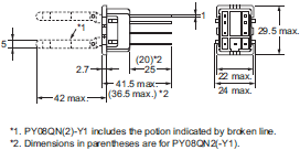
| 8 | MY2[], MY2IN(S) | Solder terminals |  | PY08 |  | PY08-Y1 |
| MY2Z[]-CR | PY08-Y3 | |||||
| MY2[], MY2IN(S) | Wrapping terminals Terminal length: 25 mm |  | PY08QN |  | PY08QN-Y1 | |
| MY2Z[]-CR | PY08QN-Y3 | |||||
| MY2[], MY2IN(S) | Wrapping terminals Terminal length: 20 mm |  | PY08QN2 |  | PY08QN2-Y1 | |
| MY2Z[]-CR | PY08QN2-Y3 | |||||
| MY2[], MY2IN(S) MY2Z[]-CR | PCB terminals |  | PY08-02 | — | — | |
| 11 | MY3 | Solder terminals |  | PY11 |  | PY11-Y1 |
| MY3 | Wrapping terminals Terminal length: 25 mm |  | PY11QN |  | PY11QN-Y1 | |
| MY3 | Wrapping terminals Terminal length: 20 mm |  | PY11QN2 |  | PY11QN2-Y1 | |
| MY3 | PCB terminals |  | PY11-02 | — | — | |
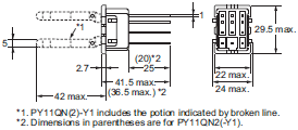
| 14 | MY4[], MY4[](S), MY2K, MY4H, MYQ4[] | Solder terminals |  | PY14 |  | PY14-Y1 |
| MY4Z[]-CBG-CR | PY14-Y3 | |||||
| MY4[], MY4[](S), MY2K, MY4H, MYQ4[] | Wrapping terminals Terminal length: 25 mm |  | PY14QN |  | PY14QN-Y1 | |
| MY4Z[]-CBG-CR | PY14QN-Y3 | |||||
| MY4[], MY4[](S), MY2K, MY4H, MYQ4[] | Wrapping terminals Terminal length: 20 mm |  | PY14QN2 |  | PY14QN2-Y1 | |
| MY4Z[]-CBG-CR | PY14QN2-Y3 | |||||
| MY4[], MY4[](S), MY4Z[]-CBG-CR MY2K, MY4H, MYQ4[] | PCB terminals |  | PY14-02 | — | — |
*1. The applicable relay model is a plug-in terminal type.
*2. The hold-down clips for connecting the relay and socket come as a set with the socket.
Hold-down Clip
| Appearance *1 | Model *2 | Weight*3 | Application |
|---|---|---|---|
 | PYC-A1 | Approx. 0.54 g | For connecting relays and sockets |
| PYC-E1 | Approx. 0.6 g | ||
 | PYC-P | Approx. 1.4 g | |
 | PYC-S | Approx. 1.8 g | For connecting sockets, socket mounting plates, and relays |
 | Y92H-3 | Approx. 0.7 g | For connecting models with built-in CR circuit for coil surge absorption (MY[]-CR) and sockets |
 | PYC-1 | Approx. 6 g |
*1.The appearance shown is one in which the relay, socket, and hold-down clip are assembled.
*2.Hold-down clips are used in sets of two. However, PYC-P and PYC-1.
*3.The weight shown above is the weight for one hold-down clip.
Socket Accessories
Hold-down Clip
List of Hold-down Clip Models
For Front-connecting Sockets
| Mounting method | DIN track mounted/screw mounted | Screw mounting only | ||||||
|---|---|---|---|---|---|---|---|---|
| Terminal Type | Push-In Plus Terminal | Screw terminal (M3 screw size) | Screw terminal (M3.5 screw size) | |||||
| Applicable sockets | PYF-08-PU-L | PYF-14-PU-L | PYF08A(-E) | PYF11A | PYF14A(-E) | PYF14T | PYF08M | |
| Number of pins | Applicable relay model *1 | Hold-down Clip model *2 | Hold-down Clip model *2 | Hold-down Clip model *2 | Hold-down Clip model *2 | Hold-down Clip model *2 | Hold-down Clip model *2 | Hold-down Clip model *2 |
| 8 | MY2[] | — | — | PYC-A1 | — | — | — | PYC-P |
| MY2IN(S)*3 | — | — | PYC-E1 | — | — | — | — | |
| MY2Z[]-CR | Y92H-3 | — | Y92H-3 | — | — | — | — | |
| 11 | MY3 | — | — | — | PYC-A1 | — | — | — |
| 14 | MY4[], MY4(Z)H, MYQ4, MYQ4N, MYQ4Z, MY4[](S), MY2K | — | — | — | — | PYC-A1 | PYC-A1 | — |
| MY4Z[]- CBG-CR *4 | — | Y92H-3 | — | — | Y92H-3 | Y92H-3 | — | |
For Back-connecting Sockets
| Terminal Type | Solder terminals | Wrapping terminals (PY[]QN terminal length: 25 mm, PY[]QN2 terminal length: 20 mm) | PCB terminals | |||||||
|---|---|---|---|---|---|---|---|---|---|---|
| Applicable sockets | PY08 | PY11 | PY14 | PY08QN(2) | PY11QN(2) | PY14QN(2) | PY08-02 | PY11-02 | PY14-02 | |
| Num- ber of pins | Applicable relay model *1 | Hold- down Clip model *2 | Hold- down Clip model *2 | Hold- down Clip model *2 | Hold-down Clip model *2 | Hold-down Clip model *2 | Hold-down Clip model *2 | Hold- down Clip model *2 | Hold- down Clip model *2 | Hold- down Clip model *2 |
| 8 | MY2[] MY2IN(S)*3 | PYC-P | — | — | PYC-P | — | — | PYC-P | — | — |
| MY2Z[]-CR | PYC-1 | — | — | PYC-1 | — | — | PYC-1 | — | — | |
| 11 | MY3 | — | PYC-P | — | — | PYC-P | — | — | PYC-P | — |
| 14 | MY4[], MY4(Z)H, MYQ4, MYQ4N, MYQ4Z, MY4[](S), MY2K | — | — | PYC-P | — | — | PYC-P | — | — | PYC-P |
| MY4Z[]- CBG-CR *4 | — | — | PYC-1 | — | — | PYC-1 | — | — | PYC-1 | |
*1. The applicable relay model is a plug-in terminal type.
*2. This is the model of the applicable hold-down clips. Hold-down clips are sold in sets of two. However, PYC-P and PYC-1
contain just one hold-down clip.
*3. We recommend using PYC-E1 hold-down clips for MY2IN(S) relays with a latching lever.
(If PYC-A1 is used with MY2IN(S), the latching lever will be blocked by the hold-down clip and the lever will not
operate.)
*4. The release lever cannot be mounted if the relay height is 53 mm or more.
If the relay height is 53 mm or more, use in combination with hold-down clip Y92H-3.
Front-connecting Socket Accessories
For Push-In Plus Terminal Sockets (PYF-08-PU(-L)/PYF-14-PU(-L))
Short Bars
| Applicable sockets | Pitch | Application | Shape/external dimensions | Number of pole | L (Length) | Insulati on color | Model*1 |
|---|---|---|---|---|---|---|---|
| PYF-08-PU(-L) PYF-14PU(-L) | 7.75 mm | Bridging contact terminals (common) |  | 2 | 15.1 | Red (R) Blue (S) Yellow(Y) | PYDN-7.75-020[] |
| 3 | 22.85 | PYDN-7.75-030[] | |||||
| 4 | 30.6 | PYDN-7.75-040[] | |||||
| 20 | 154.6 | PYDN-7.75-200[] | |||||
| 31.0 mm | For Coil terminals |  | 8 | 224.35 | PYDN-31.0-080[] |
*1. Replace the box ([]) in the model number with the code for the covering color. []Color selection: R = Red, S = Blue,
Y = Yellow
Labels
| Applicable sockets | Model |
|---|---|
| PYF-08-PU(-L) PYF-14PU(-L) | XW5Z-P4.0LB1 (1 sheet/60 pieces) |
For Screwless Terminal Sockets (PYF08S/PYF14S)
Short Bars
| Applicable sockets | Pitch | Application | Shape/external dimensions | Number of poles | Insulati on color | Model*1 |
|---|---|---|---|---|---|---|
| PYF08S | 19.7 mm | For bridging coils between sockets |  | 2 | Red (R) Blue (B) | PYDM-08S[] (50 pcs./bag) |
| PYF14S | 27.5 mm | 2 | PYDM-14S[] (50 pcs./bag) |
*1. Replace the box ([]) in the model number with the code for the covering color. []Color selection: R = Red, B = Blue
Labels
| Applicable sockets | Model |
|---|---|
| PYF08S | R99-11 (100 pcs./bag) |
| PYF14S |
Release Levers
| Applicable sockets | Shape/external dimensions | Model |
|---|---|---|
| PYF08S |  | PYCM-08S |
| PYF14S |  | PYCM-14S |
For Screw Terminal Sockets (PYF08A/PYF14A)
Short Bars
| Applicable sockets | Pitch | Application | Shape/external dimensions | Number of poles | Insulation color | Model*1 |
|---|---|---|---|---|---|---|
| PYF08A | 22 mm | For bridging adjacent sockets |  | 2 | B (Black) S (Blue) R (Red) | PYD-025B[] (2P) (10 pcs./bag) |
 | 8 | PYD-085B[] (8P) (10 pcs./bag) | ||||
| PYF14A | 29 mm |  | 2 | PYD-026B[] (2P) (10 pcs./bag) | ||
 | 8 | PYD-086B[] (8P) (10 pcs./bag) | ||||
| 7 mm | For bridging with the same socket |  | 2 | B (Black) Y (Yellow) | PYD-020B[] (2P) (50 pcs./bag) | |
 | 3 | PYD-030B[] (3P) (10 pcs./bag) |
*1. Replace the box ([]) in the model number with the code for the covering color.
Socket Mounting Plates (For Back-connecting Socket PY[]/Solder Terminals, PY[]QN(2)/Wrapping Terminals)
| Applicable Sockets | Socket Mounting Plates | |||
|---|---|---|---|---|
| Model | Models with hold-down clips | Appearance | Number of sockets | Model |
| PY08 PY08QN PY08QN2 PY11 PY11QN PY11QN2 PY14 PY14QN PY14QN2 | PY08-Y1, PY08-Y3 PY08QN-Y1, PY08QN-Y3 PY08QN2-Y1, PY08QN2-Y3 PY11-Y1 PY11QN-Y1 PY11QN2-Y1 PY14-Y1, PY14-Y3 PY14QN-Y1, PY14QN-Y3 PY14QN2-Y1, PY14QN2-Y3 |  | 1 | PYP-1 |
 | 18 | PYP-18* | ||
 | 36 | PYP-36* | ||
*You can cut the PYP-18 and PYP-36 to any required length.
Parts for Track Mounting
| Type | Appearance | Model | |
|---|---|---|---|
| DIN Tracks | 1 m |  | PFP-100N |
| 0.5 m | PFP-50N | ||
| End Plate* |  | PFP-M | |
| Spacer |  | PFP-S | |
Note: The track conforms to DIN standards.
*When mounting DIN track, please use End Plate (Model PFP-M).
last update: November 1, 2018
OMRON MY catalog
MY Miniature Power Relays/Catalog- Catalog
- Manual
- CAD
English
Global Edition
| Catalog Name | Catalog Number [size] | Last Update | |
|---|---|---|---|
| | J219-E1-02 [18871KB] | Nov 01, 201820181101 | MY/MYK/MYQ·MYH Data Sheet |
| | J213-E1-05 [7147KB] | Nov 01, 201820181101 | Push-In Plus Terminal Block Series Pamphlet |
OMRON MY specification
MY Miniature Power Relays/Specificationslast update: November 1, 2018
MY Miniature Power Relays
Ratings
Operating Coils
| Terminal Type | Classification | Number of poles | Contacts | Without operation indicator | With operation indicator |
|---|---|---|---|---|---|
| Plug-in terminals | Standard models | 2 | Single | MY2 | MY2N |
| 4 | Single | MY4 | MY4N | ||
| Bifurcated | MY4Z | MY4ZN | |||
| Models with built-in diode for coil surge absorption (DC coil specification only) | 2 | Single | MY2-D | MY2N-D2 | |
| 4 | Single | MY4-D | MY4N-D2 | ||
| Bifurcated | MY4Z-D | MY4ZN-D2 | |||
| Models with built-in CR circuit for coil surge absorption (AC coil specification only) | 2 | Single | MY2-CR | MY2N-CR | |
| 4 | Single | MY4-CR | MY4N-CR | ||
| Bifurcated | MY4Z-CR | MY4ZN-CR |
| Item | Rated current (mA) | Coil resistance (W) | Coil inductance (H) | Must operate voltage (V) | Must release voltage (V) | Maximum voltage (V) | Power consumption (VA, W) | |||
|---|---|---|---|---|---|---|---|---|---|---|
| Rated voltage (V) | 50 Hz | 60 Hz | Armature OFF | Armature ON | ||||||
| AC | 12 | 106.5 | 91 | 46 | 0.17 | 0.33 | 80% max. *1 | 30% min. *2 | 110% of rated voltage | Approx. 0.9 to 1.3 (at 60 Hz) |
| 24 | 53.8 | 46 | 180 | 0.69 | 1.3 | |||||
| 100/110 | 11.7/12.9 | 10/11 | 3,750 | 14.54 | 24.6 | |||||
| 110/120 | 9.9/10.8 | 8.4/9.2 | 4,430 | 19.2 | 32.1 | |||||
| 200/220 | 6.2/6.8 | 5.3/5.8 | 12,950 | 54.75 | 94.07 | |||||
| 220/240 | 4.8/5.3 | 4.2/4.6 | 18,790 | 83.5 | 136.4 | |||||
| DC | 12 | 72.7 | 165 | 0.73 | 1.37 | 10% min. *2 | Approx. 0.9 | |||
| 24 | 36.3 | 662 | 3.2 | 5.72 | ||||||
| 48 | 17.6 | 2,725 | 10.6 | 21.0 | ||||||
| 100/110 | 8.7/9.6 | 11,440 | 45.6 | 86.2 | ||||||
Note: 1. The rated current and coil resistance are measured at a coil temperature of 23°C with tolerances of +15%/-20%
for AC rated current and ±15% for DC coil resistance.
2. The AC coil resistance and inductance values are reference values only (at 60 Hz).
3. Operating characteristics were measured at a coil temperature of 23°C.
4. The maximum voltage capacity was measured at an ambient temperature of 23°C.
*1.There is variation between products, but actual values are 80% maximum.
To ensure operation, apply at least 80% of the rated value (at a coil temperature of 23°C).
*2.There is variation between products, but actual values are 10% minimum for DC. To ensure release, use a value that is
lower than the specified value.
| Terminal Type | Classification | Number of poles | Contacts | Without operation indicator | With operation indicator |
|---|---|---|---|---|---|
| Plug-in terminals | Standard models | 2 | Bifurcated | MY2Z | MY2ZN |
| Models with built-in diode for coil surge absorption (DC coil specification only) | 2 | Bifurcated | MY2Z-D | MY2ZN-D2 |
| Item | Rated current (mA) | Coil resistance (W) | Coil inductance (H) | Must operate voltage (V) | Must release voltage (V) | Maximum voltage (V) | Power consumption (VA, W) | |||
|---|---|---|---|---|---|---|---|---|---|---|
| Rated voltage (V) | 50 Hz | 60 Hz | Armature OFF | Armature ON | ||||||
| AC | 12 | 106.5 | 91 | 46 | 0.17 | 0.33 | 80% max. *1 | 30% min. *2 | 110% of rated voltage | Approx. 0.9 to 1.3 (at 60 Hz) |
| 24 | 53.8 | 46 | 180 | 0.69 | 1.3 | |||||
| 100/110 | 11.7/12.9 | 10/11 | 3,750 | 14.54 | 24.6 | |||||
| 110/120 | 9.9/10.8 | 8.4/9.2 | 4,430 | 19.2 | 32.1 | |||||
| 200/220 | 6.2/6.8 | 5.3/5.8 | 12,950 | 54.75 | 94.07 | |||||
| 220/240 | 4.8/5.3 | 4.2/4.6 | 18,790 | 83.5 | 136.4 | |||||
| DC | 12 | 75 | 160 | 0.73 | 1.37 | 10% min. *2 | Approx. 0.9 | |||
| 24 | 36.9 | 650 | 3.2 | 5.72 | ||||||
| 48 | 18.5 | 2,600 | 10.6 | 21.0 | ||||||
| 100/110 | 9.1/10 | 11,000 | 45.6 | 86.2 | ||||||
Note: 1. The rated current and coil resistance are measured at a coil temperature of 23°C with tolerances of +15%/-20%
for AC rated current and ±15% for DC coil resistance.
2. The AC coil resistance and inductance values are reference values only (at 60 Hz).
3. Operating characteristics were measured at a coil temperature of 23°C.
4. The maximum voltage capacity was measured at an ambient temperature of 23°C.
*1.There is variation between products, but actual values are 80% maximum.
To ensure operation, apply at least 80% of the rated value.
*2.There is variation between products, but actual values are 10% minimum for DC. To ensure release, use a value that is
lower than the specified value.
| Terminal Type | Classification | Number of poles | Contacts | With latching lever |
|---|---|---|---|---|
| Plug-in terminals | Standard models | 2 | Single | MY2IN(S) |
| 4 | Single | MY4IN(S) | ||
| Bifurcated | MY4ZIN(S) | |||
| Models with built-in diode for coil surge absorption (DC coil specification only) | 2 | Single | MY2IN-D2(S) | |
| 4 | Single | MY4IN-D2(S) | ||
| Bifurcated | MY4ZIN-D2(S) | |||
| Models with built-in CR circuit for coil surge absorption (AC coil specification only) | 2 | Single | MY4IN-CR(S) | |
| 4 | Bifurcated | MY4ZIN-CR(S) |
| Item | Rated current (mA) | Coil resistance (W) | Coil inductance (H) | Must operate voltage (V) | Must release voltage (V) | Maximum voltage (V) | Power consumption (VA, W) | |||
|---|---|---|---|---|---|---|---|---|---|---|
| Rated voltage (V) | 50 Hz | 60 Hz | Armature OFF | Armature ON | ||||||
| AC | 100/110 | 11.7/12.9 | 10/11 | 3,750 | 14.54 | 24.6 | 80% max. *1 | 30% min. *2 | 110% of rated voltage | Approx. 0.9 to 1.3 (at 60 Hz) |
| 200/220 | 6.2/6.8 | 5.3/5.8 | 12,950 | 54.75 | 94.07 | |||||
| DC | 12 | 75 | 160 | 0.73 | 1.37 | 10% min. *2 | Approx. 0.9 | |||
| 24 | 37.7 | 636 | 3.2 | 5.72 | ||||||
| 48 | 18.8 | 2,560 | 10.6 | 21 | ||||||
Note: 1. The rated current and coil resistance are measured at a coil temperature of 23°C with tolerances of +15%/-20%
for AC rated current and ±15% for DC coil resistance.
2. The AC coil resistance and inductance values are reference values only (at 60 Hz).
3. Operating characteristics were measured at a coil temperature of 23°C.
4. The maximum voltage capacity was measured at an ambient temperature of 23°C.
*1.There is variation between products, but actual values are 80% maximum.
To ensure operation, apply at least 80% of the rated value.
*2.There is variation between products, but actual values are 10% minimum for DC. To ensure release, use a value that is
lower than the specified value.
| Terminal Type | Classification | Number of poles | Contacts | Without operation indicator | With operation indicator |
|---|---|---|---|---|---|
| Plug-in terminals | Standard models | 3 | Single | MY3 | MY3N |
| 4 | Crossbar bifurcated | MY4Z-CBG | MY4ZN-CBG | ||
| PCB terminals | Standard models | 2 | Single | MY2-02 | — |
| 3 | Single | MY3-02 | — | ||
| 4 | Single | MY4-02 | — | ||
| Bifurcated | MY4Z-02 | — | |||
| Case-surface mounting | Standard models | 2 | Single | MY2F | — |
| 3 | Single | MY3F | — | ||
| 4 | Single | MY4F | — | ||
| Bifurcated | MY4ZF | — |
| Item | Rated current (mA) | Coil resistance (W) | Coil inductance (H) | Must operate voltage (V) | Must release voltage (V) | Maximum voltage (V) | Power consumption (VA, W) | |||
|---|---|---|---|---|---|---|---|---|---|---|
| Rated voltage (V) | 50 Hz | 60 Hz | Armature OFF | Armature ON | ||||||
| AC | 12 | 106.5 | 91 | 46 | 0.17 | 0.33 | 80% max. *1 | 30% min. *2 | 110% of rated voltage | Approx. 0.9 to 1.3 (at 60 Hz) |
| 24 | 53.8 | 46 | 180 | 0.69 | 1.3 | |||||
| 100/110 | 11.7/12.9 | 10/11 | 3,750 | 14.54 | 24.6 | |||||
| 110/120 | 9.9/10.8 | 8.4/9.2 | 4,430 | 19.2 | 32.1 | |||||
| 200/220 | 6.2/6.8 | 5.3/5.8 | 12,950 | 54.75 | 94.07 | |||||
| 220/240 | 4.8/5.3 | 4.2/4.6 | 18,790 | 83.5 | 136.4 | |||||
| DC | 12 | 75 | 160 | 0.73 | 1.37 | 10% min. *2 | Approx. 0.9 | |||
| 24 | 36.9 | 650 | 3.2 | 5.72 | ||||||
| 48 | 18.5 | 2,600 | 10.6 | 21.0 | ||||||
| 100/110 | 9.1/10 | 11,000 | 45.6 | 86.2 | ||||||
Note: 1. The rated current and coil resistance are measured at a coil temperature of 23°C with tolerances of +15%/-20%
for AC rated current and ±15% for DC coil resistance.
2. The AC coil resistance and inductance values are reference values only (at 60 Hz).
3. Operating characteristics were measured at a coil temperature of 23°C.
4. The maximum voltage capacity was measured at an ambient temperature of 23°C.
*1.There is variation between products, but actual values are 80% maximum.
To ensure operation, apply at least 80% of the rated value.
*2.There is variation between products, but actual values are 30% minimum for AC and 10% minimum for DC. To ensure
release, use a value that is lower than the specified value.
Contact Ratings
| Number of poles (contact configuration) | 2-pole (DPDT) | 3-pole (3PDT) | ||||||
|---|---|---|---|---|---|---|---|---|
| Contact structure | Single | Bifurcated | Single | |||||
| With latching lever (S) | ||||||||
| Load | Resistive load | Inductive load (cos φ = 0.4, L/R = 7 ms) | Resistive load | Inductive load (cos φ = 0.4, L/R = 7 ms) | Resistive load | Inductive load (cos φ = 0.4, L/R = 7 ms) | Resistive load | Inductive load (cos φ = 0.4, L/R = 7 ms) |
| Rated load | 5 A at 220 VAC 5 A at 24 VDC | 2 A at 220 VAC 2 A at 24 VDC | 5 A at 250 VAC 5 A at 30 VDC | 2 A at 250 VAC 2 A at 30 VDC | 5 A at 220 VAC 5 A at 24 VDC | 2 A at 220 VAC 2 A at 24 VDC | 5 A at 220 VAC 5 A at 24 VDC | 2 A at 220 VAC 2 A at 24 VDC |
| Rated carry current*1 | 5 A (10 A*2) | 5 A | 5 A | |||||
| Maximum switching voltage | 250 VAC, 125 VDC | 250 VAC, 125 VDC | ||||||
| Maximum switching current | 5 A | 10 A | 5 A | 5 A | ||||
| Maximum switching power | 1,100 VA 120 W | 440 VA 48 W | 2,500 VA 300 W | 500 VA 60 W | 1,100 VA 120 W | 440 VA 48 W | 1,100 VA 120 W | 440 VA 48 W |
| Contact material | Ag | Au plating + Ag | Ag | |||||
| Number of poles (contact configuration) | 4-pole (4PDT) | |||
|---|---|---|---|---|
| Contact structure | Single | |||
| With latching lever (S) | ||||
| Load | Resistive load | Inductive load (cos φ = 0.4, L/R = 7 ms) | Resistive load | Inductive load (cos φ = 0.4, L/R = 7 ms) |
| Rated load | 3 A at 220 VAC 3 A at 24 VDC | 0.8 A at 220 VAC 1.5 A at 24 VDC | 3 A at 250 VAC 3 A at 30 VDC | 0.8 A at 250 VAC 1.5 A at 30 VDC |
| Rated carry current*1 | 3 A (5 A*2) | |||
| Maximum switching voltage | 250 VAC, 125 VDC | |||
| Maximum switching current | 3 A | |||
| Maximum switching power | 660 VA 72 W | 176 VA 36 W | 1,250 VA 150 W | 200 VA 45 W |
| Contact material | Au cladding + Ag alloy | |||
| Number of poles (contact configuration) | 4-pole (4PDT) | |||||
|---|---|---|---|---|---|---|
| Contact structure | Bifurcated | Crossbar bifurcated (CBG) | ||||
| With latching lever (S) | ||||||
| Load | Resistive load | Inductive load (cos φ = 0.4, L/R = 7 ms) | Resistive load | Inductive load (cos φ = 0.4, L/R = 7 ms) | Resistive load | Inductive load (cos φ = 0.4, L/R = 7 ms) |
| Rated load | 3 A at 220 VAC 3 A at 24 VDC | 0.8 A at 220 VAC 1.5 A at 24 VDC | 3 A at 250 VAC 3 A at 30 VDC | 0.8 A at 250 VAC 1.5 A at 30 VDC | 1 A at 220 VAC 1 A at 24 VDC | 0.3 A at 220 VAC 0.5 A at 24 VDC |
| Rated carry current*1 | 3 A (5 A*2) | 1 A | ||||
| Maximum switching voltage | 250 VAC, 125 VDC | |||||
| Maximum switching current | 3 A | 1 A | ||||
| Maximum switching power | 660 VA 72 W | 176 VA 36 W | 1,250 VA 150 W | 200 VA 45 W | 220 VA 24 W | 66 VA 12 W |
| Contact material | Au cladding + Ag alloy | Au cladding + AgPd | ||||
*1.If you use a Socket, do not exceed the rated carry current of the Socket.
*2.Values shown in parentheses are for the MY[](S) model with latching lever.
Characteristics
| Number of poles (contact configuration) | 2-pole (DPDT) | 3-pole (3PDT) | ||
|---|---|---|---|---|
| Contact structure | Single | Bifurcated | Single | |
| Contact resistance*1 *2 | 50 mW max. | |||
| Operate time*3 | 20 ms max. | |||
| Release time*3 | 20 ms max. | |||
| Maximum switching frequency | Mechanical | 18,000 operations/h | ||
| Rated load | 1,800 operations/h | |||
| Insulation resistance*4 | 100 MW min. | |||
| Dielectric strength | Between coil and contacts | 2,000 VAC, 50/60 Hz for 1 min | ||
| Between contacts of different polarity | ||||
| Between contacts of the same polarity | 1,000 VAC at 50/60 Hz for 1 min | |||
| Vibration resistance | Destruction | 10 to 55 to 10 Hz, 0.5-mm single amplitude (1.0-mm double amplitude) | ||
| Malfunction | 10 to 55 to 10 Hz, 0.5-mm single amplitude (1.0-mm double amplitude) | |||
| Shock resistance | Destruction | 1,000 m/s2 | ||
| Malfunction | 200 m/s2 | |||
| Endurance | Mechanical | AC: 50,000,000 operations min. DC: 100,000,000 operations min. (switching frequency: 18,000 operations/h) | AC: 50,000,000 operations min. DC: 50,000,000 operations min. (switching frequency: 18,000 operations/h) | AC: 50,000,000 operations min. DC: 100,000,000 operations min. (switching frequency: 18,000 operations/h) |
| Electrical*5 | 500,000 operations min. (rated load, switching frequency: 1,800 operations/h) | 200,000 operations min. (rated load, switching frequency: 1,800 operations/h) | 500,000 operations min. (rated load, switching frequency: 1,800 operations/h) | |
| Failure rate P value (reference value)*6 | 1 mA at 5 VDC | 100 μA at 1 VDC | 1 mA at 5 VDC | |
| Weight | Approx. 35 g | Approx. 35 g | Approx. 35 g | |
| Number of poles (contact configuration) | 4-pole (4PDT) | |||
|---|---|---|---|---|
| Contact structure | Single | Bifurcated | Crossbar bifurcated (CBG) | |
| Contact resistance*1 *2 | 50 mW max. | 100 mW max. | ||
| Operate time*3 | 20 ms max. | |||
| Release time*3 | 20 ms max. | |||
| Maximum switching frequency | Mechanical | 18,000 operations/h | ||
| Rated load | 1,800 operations/h | |||
| Insulation resistance*4 | 100 MW min. | |||
| Dielectric strength | Between coil and contacts | 2,000 VAC, 50/60 Hz for 1 min | ||
| Between contacts of different polarity | ||||
| Between contacts of the same polarity | 1,000 VAC at 50/60 Hz for 1 min | 700 VAC at 50/60 Hz for 1 min | ||
| Vibration resistance | Destruction | 10 to 55 to 10 Hz, 0.5-mm single amplitude (1.0-mm double amplitude) | ||
| Malfunction | 10 to 55 to 10 Hz, 0.5-mm single amplitude (1.0-mm double amplitude) | |||
| Shock resistance | Destruction | 1,000 m/s2 | ||
| Malfunction | 200 m/s2 | |||
| Endurance | Mechanical | AC: 50,000,000 operations min. DC: 100,000,000 operations min. (switching frequency: 18,000 operations/h) | AC: 20,000,000 operations min. DC: 20,000,000 operations min. (switching frequency: 18,000 operations/h) | AC: 50,000,000 operations min. DC: 50,000,000 operations min. (switching frequency: 18,000 operations/h) |
| Electrical*5 | 200,000 operations min. (rated load, switching frequency: 1,800 operations/h) | 100,000 operations min. (rated load, switching frequency: 1,800 operations/h) | 50,000 operations min. (rated load, switching frequency: 1,800 operations/h) | |
| Failure rate P value (reference value)*6 | 1 mA at 1 VDC | 100 μA at 1 VDC | 100 μA at 1 VDC | |
| Weight | Approx. 35 g | Approx. 35 g | Approx. 35 g | |
Note: The data shown above are initial values.
*1.Models with latching lever are 100 mΩ maximum.
*2.Measurement conditions: 1 A at 5 VDC using the voltage drop method.
*3.Measurement conditions: With rated operating power applied, not including contact bounce.
*4.Measurement conditions: For 500 VDC applied to the same location as for dielectric strength measurement.
*5.Ambient temperature condition: 23°C
*6.This value was measured at a switching frequency of 120 operations per minute.
| Classification | Standard models | Models with built-in diode for coil surge absorption (-D)/ Models with built-in CR circuit for coil surge absorption (-CR) | ||||||
|---|---|---|---|---|---|---|---|---|
| Contacts | Single/bifurcated | Crossbar/bifurcated (CBG) | Single/bifurcated | |||||
| Features | Without operation indicator | With operation indicator | Without operation indicator | With operation indicator | Without operation indicator | With operation indicator | ||
| With latching lever | With latching lever | |||||||
| Ambient operating temperature *1 | -55 to 70°C | -55 to 60°C *2 | -55 to 70°C | -25 to 70°C | -25 to 60°C | -55 to 60°C *2 | -55 to 60°C *2 | -55 to 70°C |
| Ambient operating humidity | 5% to 85% | 5% to 85% | ||||||
*1.With no icing or condensation.
*2.This limitation is due to the diode junction temperature and elements used.
Certified Standards
UL certification (File No. E41515)
| Model | Standard number | Category | Listed/ Recognized | Operating Coil ratings | No. of poles | Contact ratings | Certified number of operations |
|---|---|---|---|---|---|---|---|
| MY2 MY2N MY2IN(S) MY2N-D2 MY2-D2 MY2IN-D2(S) MY2-CR MY2N-CR | UL508 | NRNT2 | Recognition | 6 to 240 VAC 6 to 125 VDC | 2 | 10 A, 250 VAC (General Use) 10 A, 30 VDC (General Use) 7 A, 240 VAC (General Use) 7 A, 24 VDC (Resistive) 5 A, 240 VAC (General Use) 5 A, 250 VAC (Resistive) 5 A, 30 VDC (Resistive) 3 A, 265 VAC (Resistive) | 6,000 |
| 1/6 HP, 250 VAC 1/8 HP, 265 VAC 1/10 HP, 120 VAC | 1,000 | ||||||
| B300 Pilot Duty (Same polarity) | 6,000 | ||||||
| MY2Z MY2ZN MY2-02 MY2F MY2Z-D MY2Z-D2 MY2Z-CR MY2ZN-CR | UL508 | NRNT2 | Recognition | 6 to 240 VAC 6 to 125 VDC | 2 | 7 A, 240 VAC (General Use) 7 A, 24 VDC (Resistive) 5 A, 240 VAC (General Use) 5 A, 250 VAC (Resistive) 5 A, 30 VDC (Resistive) 3 A, 265 VAC (Resistive) | 6,000 |
| 1/6 HP, 250 VAC 1/8 HP, 265 VAC 1/10 HP, 120 VAC | 1,000 | ||||||
| B300 Pilot Duty (Same polarity) | 6,000 | ||||||
| MY3 MY3N MY3-D MY3N-D2 MY3-02 MY3F | UL508 | NRNT2 | Recognition | 6 to 240 VAC 6 to 125 VDC | 3 | 5 A, 28 VDC (Resistive) 5 A, 240 VAC (General Use) | 6,000 |
| 1/6 HP, 250 VAC | 1,000 | ||||||
| MY4 MY4N MY4IN(S) MY4-D MY4N-D2 MY4IN-D2(S) MY4Z MY4ZN MY4ZIN(S) MY4Z-D MY4ZN-D2 MY4ZIN-D2(S) MY4Z-CR MY4ZN-CR MY4ZIN-CR(S) MY4-02 MY4F MY4Z-02 MY4ZF | UL508 | NRNT2 | Recognition | 6 to 240 VAC 6 to 125 VDC | 4 | 5 A, 28 VDC (General Use) (Same polarity) 5 A, 240 VAC (General Use) (Same polarity) 5 A, 30 VDC (Resistive) (Same polarity) 5 A, 250 VAC (Resistive) (Same polarity) 0.2 A, 120 VDC (Resistive) (Same polarity) | 6,000 |
| 1/6 HP, 250 VAC (Same polarity) 1/10 HP, 120 VAC (Same polarity) | 1,000 | ||||||
| B300 Pilot Duty (Same polarity) | 6,000 |
CSA certification (File No. LR31928)
| Model | Standard number | Class number | Operating Coil ratings | No. of poles | Contact ratings | Certified number of operations |
|---|---|---|---|---|---|---|
| MY2 MY2N MY2IN(S) MY2N-D2 MY2-D2 MY2IN-D2(S) MY2-CR MY2N-CR | C22.2 NO.0, No.14 | 6 to 240 VAC 6 to 125 VDC | 2 | 7 A, 240 VAC (Resistive) 7 A, 24 VDC (Resistive) 5 A, 240 VAC (General Use) 5 A, 250 VAC (Resistive) 5 A, 30 VDC (Resistive) | 6,000 | |
| 1/6 HP, 250 VAC (Same polarity) 1/10 HP, 120 VAC (Same polarity) | 1,000 | |||||
| MY2Z MY2ZN MY2-02 MY2F MY2Z-D MY2Z-D2 MY2Z-CR MY2ZN-CR | C22.2 NO.0, No.14 | 6 to 240 VAC 6 to 125 VDC | 2 | 7 A, 240 VAC (General Use) (Same polarity) 7 A, 24 VDC (Resistive) (Same polarity) 5 A, 240 VAC (General Use) (Same polarity) 5 A, 30 VDC (Resistive) 5 A, 250 VAC (Resistive) (Same polarity) 0.2 A, 120 VDC (Resistive) | 6,000 | |
| 1/6 HP, 250 VAC 1/10 HP, 120 VAC | 1,000 | |||||
| MY3 MY3N MY3-D MY3N-D2 MY3-02 MY3F | C22.2 NO.0, No.14 | 6 to 240 VAC 6 to 125 VDC | 3 | 5 A, 28 VDC (Resistive) 5 A, 240 VAC (General Use) 7 A, 240 VAC (General Use) 7 A, 24 VDC (Resistive) | 6,000 | |
| 1/6 HP, 250 VAC | 1,000 | |||||
| MY4 MY4N MY4N(S) MY4-D MY4N-D2 MY4IN-D2(S) MY4-CR MY4N-CR MY4IN-CR(S) MY4Z MY4ZN MY4ZIN(S) MY4Z-D MY4ZN-D2 MY4ZIN-D2(S) MY4Z-C MY4ZN-CR MY4ZIN-CR(S) | C22.2 No.14 | 3211 07 | 6 to 240 VAC 6 to 125 VDC | 4 | 5 A, 240 VAC (General Use) (Same polarity) 5 A, 28 VDC (General Use) (Same polarity) 5 A, 250 VAC (Resistive) (Same polarity) 5 A, 30 VDC (Resistive) (Same polarity) 0.2 A, 120 VDC (Resistive) (Same polarity) | 6,000 |
| 1/6 HP, 250 VAC (Same polarity) 1/10 HP, 120 VAC (Same polarity) | 1,000 | |||||
| B300 Pilot Duty (Same polarity) | 6,000 | |||||
| MY4-02 MY4F MY4Z-02 MY4ZF | C22.2 NO.0, No.14 | 3211 07 | 6 to 240 VAC 6 to 125 VDC | 4 | 7 A, 240 VAC (General Use) (Same polarity) 7 A, 24 VDC (Resistive) (Same polarity) 5 A, 240 VAC (General Use) (Same polarity) 5 A, 30 VDC (Resistive) 5 A, 250 VAC (Resistive) (Same polarity) 0.2 A, 120 VDC (Resistive) | 6,000 |
| 1/6 HP, 250 VAC 1/10 HP, 120 VAC | 1,000 |
TÜV Rheinland certification (Certification No. R50030059)
| Model | Operating Coil ratings | Contact ratings | Certified number of operations |
|---|---|---|---|
| MY2Z MY2ZN MY2-02 MY2F MY2Z-D MY2Z-D2 MY2Z-CR MY2ZN-CR | 6 to 125 VDC, 6 to 240 VAC | 5 A, 250 VAC (cos φ = 1.0) | 100,000 |
| MY3 MY3N MY3-D MY3N-D2 MY3-02 MY3F | 5 A, 250 VAC (cos φ = 1.0) 0.8 A, 250 VAC (cos φ = 0.4) | ||
| MY4-02 MY4F MY4Z-02 MY4ZF | 3 A, 120 VAC (cos φ = 1.0) 0.8 A, 250 VAC (cos φ = 0.4) |
CE Marking
| Model | EMC Directive | Low Voltage Directive | Machinery Directive | Safety Category |
|---|---|---|---|---|
| MY2 MY2N MY2IN(S) MY2Z MY2ZN MY2-D MY2N-D2 MY2IN-D2(S) MY2-CR MY2N-CR MY2Z-CR MY2ZN-CR MY2Z-D MY2ZN-D2 MY2F | Not applicable | Applicable | Not applicable | 1 |
| MY3 MY3N MY3-D MY3N-D2 MY3F | ||||
| MY4 MY4N MY4IN(S) MY4Z MY4ZN MY4ZIN(S) MY4-D MY4N-D2 MY4IN-D2(S) MY4Z-D MY4ZN-D2 MY4ZIN-D2(S) MY4-CR MY4N-CR MY4Z-CR MY4ZN-CR MY4F MY4ZF |
LR certification (Lloyd’s Register)
| Model | File No. | Environmental Category | Operating Coil ratings | Contact ratings | Certified number of operations |
|---|---|---|---|---|---|
| MY2 MY2N MY2IN(S) MY2-D MY2N-D2 MY2IN-D2(S) MY2-CR MY2N-CR | File No.98/10014 | ENV2,3 | 6 to 240 VAC 6 to 125 VDC | 10 A, 250 VAC (Resistive) 2 A, 250 VAC (PF0.4) 10 A, 30 VDC (Resistive) 2 A, 30 VDC (L/R = 7 ms) | MY2: 50,000 |
| MY2Z MY2ZN MY2Z-D MY2ZN-D2 | File No.90/10270 | ENV2,3 | 6 to 240 VAC 6 to 125 VDC | 2 A, 30 VDC inductive load 2 A, 200 VAC inductive load | MY2: 50,000 |
| MY4 MY4N MY4IN(S) MY4-D MY4N-D2 MY4IN-D2(S) MY4-CR MY4N-CR MY4IN-CR(S) MY4Z MY4ZN MY4ZIN(S) MY4Z-D MY4ZN-D2 MY4ZIN-D2(S) MY4Z-CR MY4ZN-CR MY4ZIN-CR(S) | File No.98/10014 | ENV2,3 | 6 to 240 VAC 6 to 125 VDC | 5 A, 250 VAC (Resistive) 0.8 A, 250 VAC (PF0.4) 5 A, 30 VDC (Resistive) 1.5 A, 30 VDC (L/R = 7 ms) | MY4: 50,000 |
VDE certification
| Model | Standard number | Certification No. | Operating Coil ratings | Contact ratings | Certified number of operations |
|---|---|---|---|---|---|
| MY2 MY2N MY2IN(S) MY2-D MY2N-D2 MY2IN-D2(S) MY2-CR MY2N-CR | EN 61810-1 | 112467UG | 6, 12, 24, 48/50, 100/110, 110/120, 200/220, 220/240 VAC 6, 12, 24, 48, 100/110, 125 VDC | 10A, 250 VAC (cos φ = 1) 10A, 30 VDC (L/R = 0 ms) | MY2: 100,000 MY4: 100,000 MY4Z: 50,000 (AC) |
| MY4 MY4N MY4IN(S) MY4Z MY4ZN MY4ZIN(S) MY4-D MY4ZN-D2 MY4IN-D2(S) MY4Z-D MY4Z-D2 MY4ZIN-D2(S) MY4-CR MY4N-CR MY4IN-CR(S) MY4Z-CR MY4ZN-CR MY4ZIN-CR(S) | 6, 12, 24, 48/50, 100/110, 110/120, 200/220, 220/240 VAC 6, 12, 24, 48, 100/110, 125 VDC | 5 A, 250 VAC (cos φ = 1) 5 A, 30 VDC (L/R = 0 ms) |
MYK Miniature Power Latching Relays
Ratings
Operating coil (AC)
| Rated voltage (V) | Set coil | Reset coil | Must operate voltage (V) | Must release voltage (V) | Maximum voltage (V) | Power consumption (VA, W) | ||||||
|---|---|---|---|---|---|---|---|---|---|---|---|---|
| Rated current (mA) | Coil resistance (W) | Rated current (mA) | Coil resistance (W) | Set coil | Reset coil | |||||||
| 50 Hz | 60 Hz | 50 Hz | 60 Hz | |||||||||
| AC | 12 | 57 | 56 | 72 | 39 | 38.2 | 130 | 80% max.* | 80% max. | 110% max. of rated voltage | Approx. 0.6 to 0.9 (at 60 Hz) | Approx. 0.2 to 0.5 (at 60 Hz) |
| 24 | 27.4 | 26.4 | 320 | 18.6 | 18.1 | 550 | ||||||
| 100 | 7.1 | 6.9 | 5,400 | 3.5 | 3.4 | 3,000 | ||||||
| DC | 12 | 110 | 110 | 50 | 235 | Approx. 1.3 | Approx. 0.6 | |||||
| 24 | 52 | 470 | 25 | 940 | ||||||||
| 48 | 27 | 1,800 | 16 | 3,000 | ||||||||
Note: 1. The rated current for AC is the value measured with a DC ammeter in half-wave rectification.
2. The rated current and coil resistance are measured at a coil temperature of 23°C with tolerances of +15%/-20%
for AC rated current and ±15% for DC coil resistance.
3. The AC coil resistance is a reference value only.
4. Operating characteristics were measured at a coil temperature of 23°C.
5. The maximum voltage capacity was measured at an ambient temperature of 23°C.
*There is variation between products, but actual values are 80% maximum.
Contact Ratings
| Number of poles (contact configuration) | 2-pole (DPDT) | |
|---|---|---|
| Contact structure | Single | |
| Load | Resistive load | Inductive load (cos φ = 0.4, L/R = 7 ms) |
| Rated load | 3 A at 220 VAC 3 A at 24 VDC | 0.8 A at 220 VAC 1.5 A at 24 VDC |
| Rated carry current | 3 A | |
| Maximum switching voltage | 250 VAC, 125 VDC | |
| Maximum switching current | 3 A | |
| Maximum switching power | 660 VA 72 W | 176 VA 36 W |
| Contact material | Au plating + Ag | |
Characteristics
| Contact resistance*1 | 50 mW max. | |
|---|---|---|
| Set | Operate time*2 | AC: 30 ms max., DC: 15 ms max. |
| Minimum pulse width | AC: 60 ms, DC: 30 ms | |
| Reset | Release time*2 | AC: 30 ms max., DC: 15 ms max. |
| Minimum pulse width | AC: 60 ms, DC: 30 ms | |
| Maximum switching frequency | Mechanical | 18,000 operations/h |
| Rated load | 1,800 operations/h | |
| Insulation resistance*3 | 100 MW min. | |
| Dielectric strength | Between coil and contacts Between contacts of different polarity | 1,500 VAC at 50/60 Hz for 1 min |
| Between contacts of the same polarity | 1,000 VAC at 50/60 Hz for 1 min | |
| Between set/reset coils | ||
| Vibration resistance | Destruction | 10 to 55 to 10 Hz, 0.5-mm single amplitude (1.0-mm double amplitude) |
| Malfunction | 10 to 55 to 10 Hz, 0.5-mm single amplitude (1.0-mm double amplitude) | |
| Shock resistance | Destruction | 1,000 m/s2 |
| Malfunction | 200 m/s2 | |
| Endurance | Mechanical | 100,000,000 operations min. (switching frequency: 18,000 operations/h) |
| Electrical*4 | 200,000 operations min. (at rated load, switching frequency: 1,800 operations/h) | |
| Failure rate P value (reference value)*5 | 1 mA at 1 VDC | |
| Ambient operating temperature*6 | -55 to 60°C | |
| Ambient operating humidity | 5% to 85% | |
| Weight | Approx. 30 g | |
Note: The data shown above are initial values.
*1.Measurement conditions: 1 A at 5 VDC using the voltage drop method.
*2.Measurement conditions: With rated operating power applied, not including contact bounce.
*3.Measurement conditions: For 500 VDC applied to the same location as for dielectric strength measurement.
*4.Ambient temperature condition: 23°C
*5.This value was measured at a switching frequency of 120 operations per minute.
*6.With no icing or condensation.
MYQ/MYH Miniature Power Sealed Relays
Operating coil (AC)
| Rated voltage (V) | Rated current (mA) | Coil resistance (W) | Coil inductance (H) | Must operate voltage (V)*1 | Must release voltage (V)*2 | Maximum voltage (V) | Power consumption (VA, W) | |||
|---|---|---|---|---|---|---|---|---|---|---|
| 50 Hz | 60 Hz | Armature OFF | Armature ON | |||||||
| AC | 24 | 53.8 | 46 | 180 | 0.69 | 1.3 | 80% max. | 30% min. | 110% max. of rated voltage | Approx. 0.9 to 1.3 (at 60 Hz) |
| 100/110 | 11.7/12.9 | 10/11 | 3,750 | 14.54 | 24.6 | |||||
| 110/120 | 9.9/10.8 | 8.4/9.2 | 4,430 | 19.2 | 32.1 | |||||
| 200/220 | 6.2/6.8 | 5.3/5.8 | 12,950 | 54.75 | 91.07 | |||||
| 220/240 | 4.8/5.3 | 4.2/4.6 | 18,790 | 83.5 | 136.4 | |||||
| DC | 12 | 75 | 165 | 0.734 | 1.37 | 10% min. | Approx. 0.9 | |||
| 24 | 36.9 | 650 | 3.2 | 5.72 | ||||||
| 48 | 18.5 | 2,600 | 10.6 | 21.0 | ||||||
| 100/110 | 9.1/10 | 11,000 | 45.6 | 86.0 | ||||||
Note: 1. The rated current and coil resistance are measured at a coil temperature of 23°C with tolerances of +15%/-20%
for AC rated current and ±15% for DC coil resistance.
2. The AC coil resistance and coil inductance values are for reference only.
3. Operating characteristics were measured at a coil temperature of 23°C.
4. The maximum voltage capacity was measured at an ambient temperature of 23°C.
*1.There is variation between products, but actual values are 80% maximum. To ensure operation, apply at least 80% of
the rated value.
*2.There is variation between products, but actual values are 30% minimum for AC and 10% minimum for DC. To ensure
release, use a value that is lower than the specified value.
Contact Ratings
Plastic Sealed Relays: MYQ
| Number of poles (contact configuration) | 4-pole (4PDT) | |
|---|---|---|
| Contact structure | Single/bifurcated | |
| Load | Resistive load | Inductive load (cos φ = 0.4, L/R = 7 ms) |
| Rated load | 1 A at 220 VAC 1 A at 24 VDC | 0.5 A at 220 VAC 0.5 A at 24 VDC |
| Rated carry current | 1 A | |
| Maximum switching voltage | 250 VAC 125 VDC | |
| Maximum switching current | 1 A | |
| Maximum switching power | 220 VA 24 W | 110 VA 12 W |
| Contact material | Au plating + Ag | |
Hermetically Sealed Relays: MYH
| Number of poles (contact configuration) | 4-pole (4PDT) | |||
|---|---|---|---|---|
| Contact structure | Single | Bifurcated | ||
| Load | Resistive load | Inductive load (cos φ = 0.4, L/R = 7 ms) | Resistive load | Inductive load (cos φ = 0.4, L/R = 7 ms) |
| Rated load | 3 A at 110 VAC 3 A at 24 VDC | 0.8 A at 110 VAC 1.5 A at 24 VDC | 3 A at 110 VAC 3 A at 24 VDC | 0.8 A at 110 VAC 1.5 A at 24 VDC |
| Rated carry current | 3 A | |||
| Maximum switching voltage | 125 VAC 125 VDC | |||
| Maximum switching current | 3 A | |||
| Maximum switching power | 330 VA 72 W | 88 VA 36 W | 330 VA 72 W | 88 VA 36 W |
| Contact material | Au plating + Ag | |||
Characteristics
| Model | MYQ | MYH | |
|---|---|---|---|
| Contact resistance*1 | 50 mW max. | ||
| Operate time*2 | 20 ms max. | ||
| Release time*2 | 20 ms max. | ||
| Maximum switching frequency | Mechanical | 18,000 operations/h | |
| Rated load | 1,800 operations/h | ||
| Insulation resistance*3 | 100 MW min. | ||
| Dielectric strength | Between coil and contacts | 1,500 VAC at 50/60 Hz for 1 min | 1,000 VAC at 50/60 Hz for 1 min |
| Between contacts of different polarity | 1,500 VAC at 50/60 Hz for 1 min | 1,000 VAC at 50/60 Hz for 1 min | |
| Between contacts of the same polarity | 1,000 VAC at 50/60 Hz for 1 min | 700 VAC at 50/60 Hz for 1 min | |
| Vibration resistance | Destruction | 10 to 55 to 10 Hz, 0.5-mm single amplitude (1.0-mm double amplitude) | |
| Malfunction | 10 to 55 to 10 Hz, 0.5-mm single amplitude (1.0-mm double amplitude) | ||
| Shock resistance | Destruction | 1,000 m/s2 | |
| Malfunction | 200 m/s2 | ||
| Endurance | Mechanical | Single contacts: AC: 50,000,000 operations min., DC: 100,000,000 operations min. Bifurcated contacts: 5,000,000 operations min., DC: 5,000,000 operations min. (switching frequency: 18,000 operations/h) | Single contacts: 50,000,000 operations min. Bifurcated contacts: 5,000,000 operations min. (switching frequency: 18,000 operations/h) |
| Electrical*4 | Single contacts: 200,000 operations min. Bifurcated contacts: 100,000 operations min. (at rated load, switching frequency: 1,800 operations/h) | Single contacts: 100,000 operations min. Bifurcated contacts: 50,000 operations min. (at rated load, switching frequency: 1,800 operations/h) | |
| Failure rate P Level (reference value)*5 | Single contacts: 1 mA at 1 VDC Bifurcated contacts: 100 μA at 1 VDC | Single contacts: 100 μA at 1 VDC Bifurcated contacts: 100 μA at 100 mVDC | |
| Ambient operating temperature*6 | -55 to 60°C | -25 to 60°C | |
| Ambient operating humidity | 5% to 85% | ||
| Weight | Approx. 35 g | Approx. 50 g | |
Note: The data shown above are initial values.
*1.Measurement conditions:1 A at 5 VDC using the voltage drop method.
*2.Measurement conditions:With rated operating power applied, not including contact bounce.
Ambient temperature condition:23°C
*3.Measurement conditions:For 500 VDC applied to the same location as for dielectric strength measurement.
*4.Ambient temperature condition:23°C
*5.This value was measured at a switching frequency of 120 operations per minute.
*6.With no icing or condensation.
Common Options (Order Separately)
Characteristics
Sockets
Socket Accessories
For Front-connecting Sockets
Short Bars
| Application | Applicable sockets | Model | Maximum carry current | Ambient operating temperature | Ambient operating humidity |
|---|---|---|---|---|---|
| Bridging contact terminals (common) | PYF-08-PU(-L) PYF-14-PU(-L) | PYDN-7.75-020[] | 20 A | -40 to 70°C | 5% to 85% |
| PYDN-7.75-030[] | |||||
| PYDN-7.75-040[] | |||||
| PYDN-7.75-200[] | |||||
| PYF08A | PYD-025B[] | 20 A (However, 18 A when 70°C) | -40 to 70°C (with no icing or condensation) | 45% to 85% (with no icing or condensation) | |
| PYD-085B[] | |||||
| PYF14A | PYD-026B[] | ||||
| PYD-086B[] | |||||
| PYD-020B[] | |||||
| PYD-030B[] | |||||
| For Coil terminals | PYF-08-PU(-L) PYF-14-PU(-L) | PYDN-31.0-080[] | 20 A | -40 to 70°C | 5% to 85% |
| PYF08S | PYDM-08S[] | 10 A | -40 to 70°C | 5% to 85% | |
| PYF14S | PYDM-14S[] | 10 A | -40 to 70°C | 5% to 85% |
Certified Standards
CSA certification (File No. LR031928)
| Model | Ratings | Class number | Standard number |
|---|---|---|---|
| PYF-08-PU | 10 A, 250 V | 3211 07 | CSA C22.2 No14 |
| PYF-14-PU | 6 A, 250 V * | ||
| PYF08S | 10 A, 250 V | ||
| PYF14S | 5 A, 250 V | ||
| PY[] PYF[]A(-E) | 7 A, 250 V |
* When power is supplied to all four poles, use with a total power current that does not exceed 20 A.
UL certification (File No. E87929)
| Model | Ratings | Standard number | Category | Listed/Recognized |
|---|---|---|---|---|
| PYF-08-PU | 10 A, 250 V | UL508 | SWIV2 | Recognition |
| PYF-14-PU | 6 A, 250 V * | |||
| PYF08S PYF14S | 10 A, 250 V | |||
| PY[] PYF[]A(-E) | 7 A, 250 V |
* When power is supplied to all four poles, use with a total power current that does not exceed 20 A.
TÜV Rheinland certification
| Model | Ratings | Standard number | Certification No. |
|---|---|---|---|
| PYF-08-PU | 10 A, 250 V* | EN 61984 | R50327595 |
| PYF-14-PU | 6 A, 250 V |
*Ratings are for an ambient temperature of 55°C or below. At an ambient temperature of 70°C, the value is 7 A.
VDE certification
| Model | Standard number | Certification No. |
|---|---|---|
| PYF08S | VDE0627 (EN61984) | 40015509 |
| PYF14 |
last update: November 1, 2018
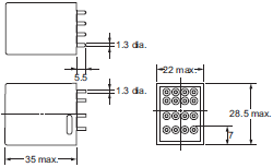
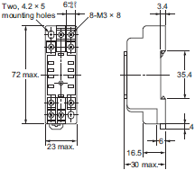
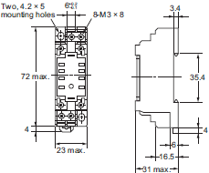
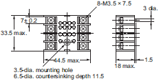
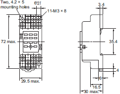
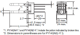
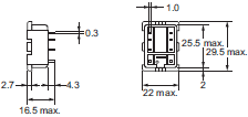
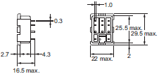
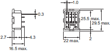
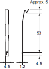
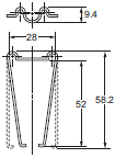
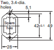
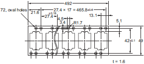
OMRON MY dimension
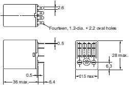
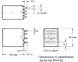
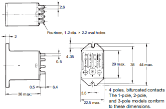
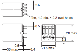
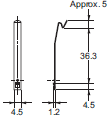
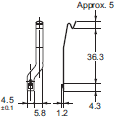
MY Miniature Power Relays/Dimensionslast update: November 1, 2018
(Unit: mm)
MY Miniature Power Relays
Plug-in terminals
MY2, MY2N, MY2-D and MY2N-D2
MY2-CR, MY2N-CR
MY2Z, MY2ZN, MY2Z-D and MY2ZN-D2
MY2Z-CR, MY2ZN-CR
MY3, M Y3N, MY3-D, and MY3N-D2
MY4, MY4N, MY4-D and MY4N-D2
MY4-CR, MY4N-CR
MY4Z, MY4ZN, MY4Z-D, MY4ZN-D2
MY4Z-CR, MY4ZN-CR
MY2IN(S)
MY2IN-D2(S)
MY(Z)IN(S)
MY4(Z)IN-D2(S)
MY4(Z)IN-CR(S)
MY4Z-CBG
PCB terminals
MY2-02
MY3-02
MY4-02
MY4Z-02
Case-surface mounting
MY2F
MY3F
MY4F
MY4ZF
MYK Miniature Power Latching Relays
Plug-in terminals
MY2K
PCB terminals
MY2K-02
MYQ/MYH Miniature Power Sealed Relays
Plug-in terminals
Plastic Sealed Relays
MYQ4(Z)(N)
Hermetically Sealed Relays
MY4(Z)H
PCB terminals
Plastic Sealed Relays
MYQ4(Z)-02
Hermetically Sealed Relays
MY4(Z)H-0
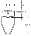
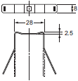
Common Options (Order Separately)
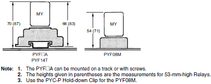
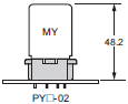
Height with Socket
Front-connecting Sockets
Push-In Plus Terminal (PYF-[]-PU)

Screwless terminal (PYF08S, PYF14S)
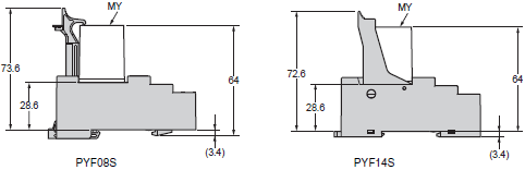
Screw terminal (PYF[]A(-E), PYF14T, PYF08M)
Back-connecting Sockets
Solder terminals/wrapping terminals (PY[])

PCB terminals (PY[]-02)
Front-connecting Sockets
Push-In Plus Terminal
PYF-08-PU(-L)
* The PYF-08-PU-L Sockets do not have release levers.
PYF-14-PU(-L)
* The PYF-14-PU-L Sockets do not have release levers.
Screwless terminal
PYF08S
PYF14S
Front-connecting Sockets
Screw terminal
PYF08A
PYF08A-E (Finger-protection structure)
PYF08M
PYF11A
PYF14A
PYF14A-E (Finger-protection structure)
PYF14T
Back-connecting Socket
Solder terminals
PY08
PY11
PY11-Y1
PY14
PY14-Y1
PY14-Y3
Wrapping terminals
PY08QN
PY08QN2
PY08QN2-Y1
PY08QN2-Y3
PY11QN
PY11QN2
PY11QN-Y1
PY11QN2-Y1
PY14QN/PY14QN2
PY14QN-Y1/PY14QN2-Y1
PY14QN-Y3 (L = 60 max.)
PY14QN2-Y3 (L = 60 max.)
PCB terminals
PY08-02
PY11-02
• This is not a flux-tight structure. We recommend manual soldering for this product.
PY14-02
Socket Accessories
Hold-down Clip
PYC-A1 1 set (2 pcs.)
PYC-E1 1 set (2 pcs.)
PYC-P
PYC-S 1 set (2 pcs.)
Y92H-3 1 set (2 pcs.)
PYC-1
Socket Mounting Plates
PYP-1
PYP-18
PYP-36

Accessories for DIN Track Mounting
DIN Tracks
PFP-100N
PFP-50N
End Plate
PFP-M
Spacer
PFP-S
last update: November 1, 2018
- NO. MY
- TYPE:General Purpose Relays For Control Panel
 Copyright Statement
 - DATE:2021-06-08
- Associated products:
G2RV-SR Slim I/O Relay/Features LY Bi-power Relays/Features