OMRON MMKRelays/ General Purpose Relays/For Control Panel
OMRON MMK Relays
OMRON MMK Dimensions
/Images/l_960-25-118984-198x198.jpglast update: December 19, 2013
• Low power consumption due to mechanical latch for economic operation.
• Relays with mixed coil specifications can be produced (e.g., AC set coil and DC reset coil).
• Operational response fast enough to enable pulse signal power applications.
• Ambient operating temperature: –10°C to 55°C.
last update: December 19, 2013
Purchase the OMRON For Control Panel Please fill in the following
If you have just landed here, this product OMRON MMK Relays,Relays is offered online by Tianin FLD Technical Co.,Ltd. This is an online store providing Relays at wholesale prices for consumers. You can call us or send enquiry, we would give you the prices, packing,deliverty and more detailed information on the MMK We cooperate with DHL,TNT,FEDEX,UPS,EMS,etc.They guarantee to meet your needs in terms of time and money,even if you need your OMRON MMKRelays tomorrow morning (aka overnight or next day air) on your desk, 2, 3 days or more.Note to international customers, YES, we ship worldwide.
G7SA Relays with Forcibly Guided Contacts/Features
TL-W Flat Inductive Proximity Sensor/Features
NX-SI / SO Safety I/O Unit/Features
E5CD-800 Digital Temperature Controller (Simple Type) (48 x 48 mm)/Features
NX-ILM400 NX-series IO-Link Master Unit/Features
OMRON MMK lineup
MMK Latching Relay/Lineuplast update: October 21, 2015
Available Models
When your order, specify the rated voltage.
Open Coils (with Solder Terminals)
| Type | Contact form | Relay model | Available rated voltage |
|---|---|---|---|
| Standard | DPDT | MM2K | 100/(110), 200/(220) VAC 12, 24, 48, 100/110, 200/220 VDC |
| 3PDT | MM3K | 100/(110), 200/(220) VAC 48, 100/110 VDC | |
| 4PDT | MM4K | 200/(220) VAC 12, 24, 48, 100/110, 200/220 VDC | |
| DC-switching | DPDT | MM2XK | 24, 100/110 VDC |
| 3PDT | MM3XK | 200/(220) VAC 100/110 VDC | |
| 4PDT | MM4XK | 100/(110) VAC 100/110 VDC |
Open Coils (with Screw Terminals)
| Type | Contact form | Relay model | Available rated voltage |
|---|---|---|---|
| Standard | DPDT | MM2KB | 100/(110), 200/(220) VAC 12, 24, 48, 100/110 VDC |
| 3PDT | MM3KB | 100/(110), 200/(220) VAC 12, 48, 100/110 VDC | |
| 4PDT | MM4KB | 24, 100/(110), 200/(220) VAC 100/110 VDC | |
| DC-switching | DPDT | MM2XKB | 100/(110), 200/(220) VAC 12, 24, 48, 100/110, 200/220 VDC |
| 3PDT | MM3XKB | 200/(220) VAC 24, 100/110 VDC | |
| 4PDT | MM4XKB | 24, 48, 100/110, 125, 200/220 VDC |
Cased Coils (Plug-in Terminals)
| Type | Contact form | Relay model | Available rated voltage |
|---|---|---|---|
| Standard | DP | MM2KP | 6, 12, 24, 100/(110), 200/(220) VAC 12, 24, 48, 100/110, 125, 200/220 VDC |
| 3P | MM3KP | 24, 100/(110), 200/(220) VAC 6, 12, 24, 48, 100/110, 125, 200/220 VDC | |
| 4P | MM4KP | 24, 100/(110), 200/(220) VAC 6, 12, 24, 48, 100/110, 125, 200/220 VDC | |
| DC-switching | DP | MM2XKP | 24, 100/(110), 200/(220) VAC 12, 24, 48, 100/110, 125, 200/220 VDC |
| 3P | MM3XKP | 100/(110), 200/(220) VAC 24, 48, 100/110, 125, 200/220 VDC | |
| 4P | MM4XKP | 100/(110), 200/(220) VAC 6, 12, 24, 48, 100/110, 125, 200/220 VDC | |
| Conforming to auxiliary power relay specifications | 4P | MM4KP-JD | 24, 100/(110), 115, 200/(220) VAC 24, 100/110, 125, 200/220 VDC |
| Conforming to auxiliary power relay specifications for DC-switching | 4P | MM4XKP-JD | 100/(110), 115, 200/(220) VAC 24, 48, 100/110, 125, 200/220 VDC |
Accessories (Order Separately)
Sockets
| Relay | DIN Track/Front-connecting Socket | Back-connecting Socket |
|---|---|---|
| Screw terminals | Solder terminals | |
| MM2(X)KP | 11PFA | PL11 |
| MM3(X)KP MM4(X)KP | 14PFA | PL15 |
| MM4(X)KP-JD | 14PFA | --- |
Mounting Brackets
| Contact form | Model |
|---|---|
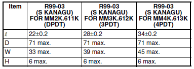
| DPDT | R99-03 (S KANAGU) FOR MM2K.611K |
| 3PDT | R99-03 (S KANAGU) FOR MM3K.612K |
| 4PDT | R99-03 (S KANAGU) FOR MM4K.613K |
last update: October 21, 2015
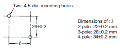
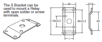
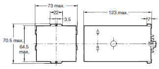
OMRON MMK dimension
MMK Latching Relay/Dimensionslast update: April 2, 2018
(Unit: mm)
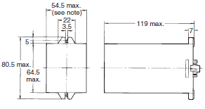
Open Relays with Solder Terminals
MM2(X)K, MM3(X)K, MM4(X)K
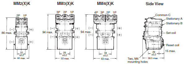
Note: Connect the common (C) of MM[]XK to positive (+).
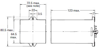
Open Relays with Screw Terminals
MM2(X)KB, MM3(X)KB, MM4(X)KB
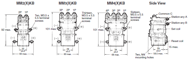
Note: Connect the common (C) of MM[]XKB to positive (+).
Mounting Holes (Direct Mounting)
Note: The tolerance is ±0.2.
Mounting Bracket (S Bracket)
R99-03 (S KANAGU) FOR MM[]
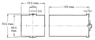
Cased Relays with Plug-in Terminal
MM2(X)KP
Note: It is recommended that 55 mm min. is allowed for this side because the MM2XKP has a curved protective plate on
the side.
MM3(X)KP, MM4(X)KP
Note: It is recommended that 73 mm min. is allowed for this side because the MM3XKP and MM4XKP have a curved
protective plate on the side.
MM4KP-JD
MM4XKP-JD
last update: April 2, 2018
OMRON MMK catalog
MMK Latching Relay/Catalog- Catalog
- Manual
- CAD
English
Global Edition
| Catalog Name | Catalog Number [size] | Last Update | |
|---|---|---|---|
| | - [2115KB] | Apr 02, 201820180402 | MMK Data Sheet |
OMRON MMK specification
MMK Latching Relay/Specificationslast update: September 07, 2016
Coil Ratings
Set Coil
| Rated voltage (V) | Rated current (mA) | Coil resistance (Ω) | Set volt. | Max volt. | Power con- sump- tion (VA or W) | |||||||||
|---|---|---|---|---|---|---|---|---|---|---|---|---|---|---|
| DP | 3P, 4P | DP | 3P, 4P | |||||||||||
| Open Relays | Cased | Open Relays | Cased | Open Relays | Cased | Open Relays | Cased | |||||||
| 50 Hz | 60 Hz | 50 Hz | 60 Hz | 50 Hz | 60 Hz | 50 Hz | 60 Hz | % of rated voltage | ||||||
| AC | 6 | 790 | 655 | 690 | 590 | 1,285 | 1,100 | 1,165 | 1,000 | 1.1 | 0.46 | 80% max. | 110 % | Initial: DP: Approx. 6.2 3P, 4P: Approx. 12 Rated: DP: Approx. 3.5 (3.9) 3P, 4P: Approx. 6 (6.6) * |
| 12 | 395 | 325 | 345 | 295 | 640 | 550 | 580 | 500 | 4.7 | 1.9 | ||||
| 24 | 195 | 160 | 170 | 145 | 320 | 275 | 290 | 250 | 19 | 8.2 | ||||
| 100/ (110) | 47 | 39/45 | 41 | 35/40 | 77 | 66/76 | 70 | 60/68 | 340 | 141 | ||||
| 200/ (220) | 23.5 | 19.5/ 22.5 | 20.5 | 17.5/ 20 | 38.5 | 33/38 | 35 | 30/34 | 1,540 | 563 | ||||
| DC | 6 | 340 | 450 | 17.5 | 13.4 | DP: Approx. 2.1 3P, 4P: Approx. 2.7 | ||||||||
| 12 | 176 | 220 | 68 | 54 | ||||||||||
| 24 | 87 | 94 | 275 | 255 | ||||||||||
| 48 | 41 | 52 | 1,180 | 930 | ||||||||||
| 100/ 110 | 17/19 | 22/24.5 | 5,750 | 4,500 | ||||||||||
| 200/ 220 | 8.6/9.5 | 11/12 | 23,200 | 18,000 | ||||||||||
Note: 1. The rated current and coil resistance are measured at a coil temperature of 23°C with tolerances of +15%/-20%
for AC rated current and ±15% for DC coil resistance.
2. Performance characteristic data are measured at a coil temperature of 23°C.
3. The AC coil resistance values are reference values.
4. The maximum voltage is one that is applicable instantaneously to the Relay coil at an ambient temperature of
23°C and not continuously.
* Values in parentheses are for open relays.
Reset Coil
| Rated voltage (V) | Rated current (mA) | Coil resistance (Ω) | Reset voltage | Maximum voltage | Power consumption (VA or W) | ||
|---|---|---|---|---|---|---|---|
| 50 Hz | 60 Hz | % of rated voltage | |||||
| AC | 6 | 770 | 690 | 2.3 | 80% max. | 110% | Initial: Approx. 6.5 Rated: Approx. 4.1 |
| 12 | 385 | 345 | 9.2 | ||||
| 24 | 191 | 170 | 35 | ||||
| 100/(110) | 46 | 41/46 | 739 | ||||
| 200/(220) | 23 | 20/23 | 3,030 | ||||
| DC | 6 | 422 | 14.2 | Approx. 2.8 | |||
| 12 | 215 | 56 | |||||
| 24 | 109 | 220 | |||||
| 48 | 58 | 832 | |||||
| 100/110 | 25/27 | 4,040 | |||||
| 200/220 | 12.2/13.5 | 16,330 | |||||
Note: 1. The rated current and coil resistance are measured at a coil temperature of 23°C with tolerances of +15%/-20%
for AC rated current and ±15% for DC coil resistance.
2. Performance characteristic data are measured at a coil temperature of 23°C.
3. The AC coil resistance values are reference values.
4. The maximum voltage is one that is applicable instantaneously to the Relay coil at an ambient temperature of
23°C and not continuously.
Coils (Conforming to Auxiliary Power Relay Specifications)
| Rated voltage (V) | Rated current (mA) | Coil resistance (Ω) | Set volt- age | Reset volt- age | Max. volt- age | Op- era- tion level (JEC- 174D) | Power consumption (VA or W) | ||||||||
|---|---|---|---|---|---|---|---|---|---|---|---|---|---|---|---|
| Set coil | Reset coil | Set coil | Reset coil | Set coil | Reset coil | ||||||||||
| 50 Hz | 60 Hz | 50 Hz | 60 Hz | % of rated voltage | Initial | Rated | Initial | Rated | |||||||
| AC | 24 | 245 | 210 | 191 | 170 | 8.5 | 35 | 80% max. | 80% max. | 110% | A | Approx. 6.3 | Approx. 5.1 | Approx. 6.5 | Approx. 4.1 |
| 100/ (110) | 58.5 | 51/ 58 | 46 | 41/ 46 | 150 | 739 | |||||||||
| 110 | 53 | 46 | 42 | 37.3 | 182 | 835 | |||||||||
| 115 | 51 | 44 | 40 | 35.7 | 210 | 885 | |||||||||
| 200/ (220) | 29 | 25.5 /29 | 23 | 20.5 /23 | 620 | 3,030 | |||||||||
| 220 | 26.5 | 23 | 21 | 18.6 | 780 | 3,420 | |||||||||
| DC | 24 | 94 | 109 | 255 | 220 | Approx. 2.7 | Approx. 2.8 | ||||||||
| 48 | 52 | 58 | 930 | 832 | |||||||||||
| 100/ 110 | 22/24.5 | 25/27 | 4,500 | 4,040 | |||||||||||
| 125 | 22 | 23.5 | 5,800 | 5,330 | |||||||||||
| 200/ 220 | 11/12 | 12.2/13.5 | 18,000 | 16,330 | |||||||||||
Note: 1. The rated current and coil resistance are measured at a coil temperature of 23°C with tolerances of +15%/-20%
for AC rated current and ±15% for DC coil resistance.
2. The AC coil resistance and coil inductance values are for reference only.
3. Performance characteristic data are measured at a coil temperature of 23°C.
4. The maximum voltage is one that is applicable instantaneously to the Relay coil at an ambient temperature of
23°C and not continuously.
Contact Ratings
Standard Relays
| Item | Open Relays: MM2K(B), MM3K(B), MM4K(B) | Cased Relays: MM2KP, MM3KP, MM4KP | ||
|---|---|---|---|---|
| Resistive load (cosφ = 1) | Inductive load (cosφ=0.4, L/R=7 ms) | Resistive load (cosφ = 1) | Inductive load (cosφ=0.4, L/R=7 ms) | |
| Contact mechanism | Single | |||
| Contact material | Ag | |||
| Rated load | 10 A at 220 VAC 7 A at 24 VDC | 5 A at 220 VAC 4 A at 24 VDC | ||
| Rated carry current | 10 A | 5 A | ||
| Max. switching voltage | 250 VAC, 250 VDC | 250 VAC, 250 VDC | ||
| Max. switching current | 10 A | 5 A | ||
| Max. switching power (reference value) | 2,200 VA, 168 W | 1,100 VA, 96W | ||
DC-switching Relays
| Item | Open Relays: MM2XK(B), MM3XK(B), MM4XK(B) | Cased Relays: MM2XKP, MM3XKP, MM4XKP | ||
|---|---|---|---|---|
| Resistive load (cosφ = 1) | Inductive load (cosφ=0.4, L/R=7 ms) | Resistive load (cosφ = 1) | Inductive load (cosφ=0.4, L/R=7 ms) | |
| Contact mechanism | Single | |||
| Contact material | Ag | |||
| Rated load | 7 A at 110 VDC | 6 A at 110 VDC | 5 A at 110 VDC | |
| Rated current flow | 10 A | 5 A | ||
| Max. switching voltage | 250 VAC, 250 VDC | 250 VAC, 250 VDC | ||
| Max. switching current | 10 A | 5 A | ||
| Max. switching power (reference value) | 800 W, 20 VA *1 | 660 W, 20 VA *1 | 700 W, 20 VA *1 | 600 W, 20 VA *1 |
Note: 1. When switching DC inductive loads at 125 V or more, an unstable region exists for a switching current of between
0.5 and 2.5 A. The Relay will not turn OFF in this region. Use a switching current of 0.5 A or less when switching
125 VDC or more.
2. If L/R exceeds 7 ms when switching DC inductive loads, an arc-breaking time of up to 50 ms must be considered
in application and the circuit must be designed to ensure that an arc-breaking time of 50 ms is not exceeded.
*1. Refer to Switching an Switching an AC Load with a DC-switching Model ("X" Model) on Data Sheet.
Contacts (Conforming to Auxiliary Power Relay Specifications)
| Item | MM4KP-JD | MM4XKP-JD | ||
|---|---|---|---|---|
| Resistive load (cosφ = 1) | Inductive load (cosφ = 0.4, L/R= 7 ms) | Resistive load (cosφ = 1) | Inductive load (cosφ = 0.4, L/R= 7 ms) | |
| Contact mechanism | Single | |||
| Contact material | Ag | |||
| Rated load | 5 A at 220 VAC, 4 A at 24 VDC | 5 A at 110 VDC | ||
| Rated carry current | 5 A | |||
| Max. switching voltage | 250 VAC, 250 VDC | |||
| Max. switching current | 5 A | |||
Note: 1. When switching DC inductive loads at 125 V or more, an unstable region exists for a switching current of between
0.5 and 2.5 A. The Relay will not turn OFF in this region. Use a switching current of 0.5 A or less when switching
125 VDC or more.
2. If L/R exceeds 7 ms when switching DC inductive loads, an arc-breaking time of up to 50 ms must be considered
in application and the circuit must be designed to ensure that an arc-breaking time of 50 ms is not exceeded.
Characteristics
| Item | Open or bifurcated-contact Relays |
|---|---|
| Contact resistance *2 | 50 mΩ max. |
| Set time *3 | AC: 30 ms max.; DC: 60 ms max. (minimum pulse width for AC and DC: 100 ms) |
| Reset time *3 | 30 ms max. (minimum pulse width for AC and DC: 100 ms) |
| Max. operating frequency | Mechanical: 1,800 operations/hr Electrical: 1,800 operations/hr (under rated load) |
| Insulation resistance *4 | 100 MΩ min. (at 500 VDC) |
| Dielectric strength | 1,500 VAC, 50/60 Hz for 1 min between contacts of same polarity 2,000 VAC, 50/60 Hz for 1 min between contacts of different polarity, between contacts and coil, and between set and reset coils |
| Vibration resistance | Destruction: 10 to 55 to 10 Hz, 0.375 mm single amplitude (0.75 mm double amplitude) Malfunction: 10 to 35 to 10 Hz, 0.5 mm single amplitude (1.0 mm double amplitude) |
| Shock resistance | Destruction: 500 m/s2 Malfunction: 50 m/s2 |
| Endurance | Mechanical: 2,500,000 operations min. (at 1,800 operations/hr) Electrical: 500,000 operations min. (at 1,800 operations/hr under rated load) *5 |
| Error rate (level P) (Reference value) *6 | 10 mA at 5 VDC |
| Ambient temperature | Operating: -10°C to 55°C (with no icing or condensation) |
| Ambient humidity | Operating: 5% to 85% |
| Weight | Standard Relays MM2K: Approx. 255 g MM3K: Approx. 390 g MM4K: Approx. 420 g MM2KP: Approx. 375 g MM3KP: Approx. 550 g MM4KP: Approx. 570 g DC-switching Relays MM2XK: Approx. 260 g MM2XK: Approx. 395 g MM4XK: Approx. 430 g MM2XKP: Approx. 380 g MM3XKP: Approx. 555 g MM4XKP: Approx. 580 g |
*1. The data shown above are initial values.
*2. The contact resistance was measured with 1 A at 5 VDC using the voltage drop method.
*3. The set or reset time was measured with the rated voltage imposed with any contact bounce ignored at an ambient
temperature of 23°C.
*4. The insulation resistance was measured with a 500-VDC megger applied to the same places as those used for
checking the dielectric strength.
*5. The electrical endurance was measured at an ambient temperature of 23°C.
*6. This value was measured at a switching frequency of 60 operations per minute.
Characteristics (Conforming to Auxiliary Power Relay Specifications)
| Vibration resistance | Destruction: 10 to 55 to 10 Hz, 0.375 mm single amplitude (0.75 mm double amplitude) Malfunction: 10 to 22 to 10 Hz, 0.5 mm single amplitude (1.0 mm double amplitude) |
|---|---|
| Shock resistance | Destruction: 300 m/s2 Malfunction: 30 m/s2 |
| Endurance | Mechanical: 2,500,000 operations min. (at 1,800 operations/hr) Electrical: 500,000 operations min. (at 1,800 operations/hr under rated load) *2 |
| Error rate (level P) (Reference value) *3 | 10 mA at 5 VDC |
| Ambient temperature | Operating: -10°C to 40°C (with no icing or condensation) |
| Ambient humidity | Operating: 5% to 85% |
| Weight | MM4KP-JD: Approx. 570 g MM4XKP-JD: Approx. 580 g |
*1. The data shown above are initial values.
*2. The electrical endurance was measured at an ambient temperature of 23°C.
*3. This value was measured at a switching frequency of 60 operations per minute.
last update: September 07, 2016
- NO. MMK
- TYPE:General Purpose Relays For Control Panel
 Copyright Statement
 - DATE:2021-06-16
- Associated products:
MM Power Relay/Features G4Q Ratchet Relay/Features