OMRON G7JRelays/ General Purpose Relays/For Built-in
OMRON G7J Relays
OMRON G7J Dimensions
/Images/l_962-25-118875-198x198.jpglast update: December 19, 2013
• Miniature hinge for maximum switching power for motor loads as well as resistive and inductive loads.
• No contact chattering for momentary voltage drops up to 50% of rated voltage.
• Withstanding more than 4 kV between contacts that are different in polarity and between the coil and contacts.
• Flame-resistant materials (UL94V-0-qualifying) used for all insulation material.
• Standard models approved by UL and CSA.
last update: December 19, 2013
Purchase the OMRON For Built-in Please fill in the following
If you have just landed here, this product OMRON G7J Relays,Relays is offered online by Tianin FLD Technical Co.,Ltd. This is an online store providing Relays at wholesale prices for consumers. You can call us or send enquiry, we would give you the prices, packing,deliverty and more detailed information on the G7J We cooperate with DHL,TNT,FEDEX,UPS,EMS,etc.They guarantee to meet your needs in terms of time and money,even if you need your OMRON G7JRelays tomorrow morning (aka overnight or next day air) on your desk, 2, 3 days or more.Note to international customers, YES, we ship worldwide.
E3NW Sensor Communications Unit/Features
E2F Resin-case Proximity Sensor/Features
EE-SPW311 / 411 Long-distance Through-beam Photomicrosensor/Features
H3DT-N / -L Multi-range, Multi-mode Timer/Features
K3HB-V Weighing Indicator/Features
OMRON G7J lineup
G7J Power Relay/Lineuplast update: October 20, 2015
When your order, specify the rated voltage.
| Mounting type | Contact form | PCB terminals | Screw terminals | Quick-connect terminals |
|---|---|---|---|---|
| PCB mounting | 4PST-NO | G7J-4A-P, G7J-4A-PZ | --- | --- |
| 3PST-NO/SPST-NC | G7J-3A1B-P, G7J-3A1B-PZ | --- | --- | |
| DPST-NO/DPST-NC | G7J-2A2B-P | --- | --- | |
| W-bracket (see note) | 4PST-NO | --- | G7J-4A-B | G7J-4A-T, G7J-4A-TZ |
| 3PST-NO/SPST-NC | --- | G7J-3A1B-B, G7J-3A1B-BZ | G7J-3A1B-T, G7J-3A1B-TZ | |
| DPST-NO/DPST-NC | --- | G7J-2A2B-B | G7J-2A2B-T |
Note: These Relays need a W-bracket (sold separately) for mounting.
When ordering specify the voltage.

PCB Terminals
| Contact form | Model | Rated voltage |
|---|---|---|
| 4PST-NO | G7J-4A-P | 24, 50, 100/120, 200/240 VAC |
| 12, 24, 48, 100 VDC | ||
| 3PST-NO/SPST-NC | G7J-3A1B-P | 24, 50, 100/120, 200/240 VAC |
| 12, 24, 48, 100 VDC | ||
| DPST-NO/DPST-NC | G7J-2A2B-P | 24, 50, 100/120, 200/240 VAC |
| 12, 24, 48, 100 VDC |
PCB Terminals (Bifurcated Contact)
| Contact form | Model | Rated voltage |
|---|---|---|
| 4PST-NO | G7J-4A-PZ | 200/240 VAC |
| 24 VDC | ||
| 3PST-NO/SPST-NC | G7J-3A1B-PZ | 200/240 VAC |
| 12, 24 VDC |
W-bracket Screw Terminals
| Contact form | Model | Rated voltage |
|---|---|---|
| 4PST-NO | G7J-4A-B | 24, 50, 100/120, 200/240 VAC |
| 12, 24, 48, 100 VDC | ||
| 3PST-NO/SPST-NC | G7J-3A1B-B | 24, 50, 100/120, 200/240 VAC |
| 12, 24, 48, 100 VDC | ||
| DPST-NO/DPST-NC | G7J-2A2B-B | 24, 50, 100/120, 200/240 VAC |
| 12, 24, 48, 100 VDC |
Screw Terminals (Bifurcated Contact)
| Contact form | Model | Rated voltage |
|---|---|---|
| 3PST-NO/SPST-NC | G7J-3A1B-BZ | 200/240 VAC |
| 12, 24 VDC |
W-bracket Tab Terminals
| Contact form | Model | Rated voltage |
|---|---|---|
| 4PST-NO | G7J-4A-T | 24, 50, 100/120, 200/240 VAC |
| 12, 24, 48, 100 VDC | ||
| 3PST-NO/SPST-NC | G7J-3A1B-T | 24, 50, 100/120, 200/240 VAC |
| 12, 24, 48, 100 VDC | ||
| DPST-NO/DPST-NC | G7J-2A2B-T | 24, 50, 100/120, 200/240 VAC |
| 12, 24, 48, 100 VDC |
W-bracket Tab Terminals (Bifurcated Contact)
| Contact form | Model | Rated voltage |
|---|---|---|
| 4PST-NO | G7J-4A-TZ | 200/240 VAC |
Consult your OMRON representative for details on models not mentioned in this document.
Accessories (Order Separately)
| Name | Model | Applicable Relay |
|---|---|---|
| W-bracket | R99-04 for G5F | G7J-4A-B G7J-3A1B-B(Z) G7J-2A2B-B G7J-4A-T(Z) G7J-3A1B-T G7J-2A2B-T |
last update: October 20, 2015
OMRON G7J catalog
G7J Power Relay/Catalog- Catalog
- Manual
- CAD
English
Global Edition
| Catalog Name | Catalog Number [size] | Last Update | |
|---|---|---|---|
| | - [854KB] | Oct 20, 201520151020 | G7J Data Sheet |
OMRON G7J specification
G7J Power Relay/Specificationslast update: September 24, 2012
Coil Ratings
| Rated voltage | Rated current | Coil resistance | Must-operate voltage | Must-release voltage | Max. voltage | Power consumption | |
|---|---|---|---|---|---|---|---|
| AC | 24 VAC | 75 mA | --- | 75% max. of rated voltage | 15% min. of rated voltage | 110% of rated voltage | Approx. 1.8 to 2.6 VA |
| 50 VAC | 36 mA | --- | |||||
| 100 to 120 VAC | 18 to 21.6 mA | --- | |||||
| 200 to 240 VDC | 9 to 10.8 mA | --- | |||||
| DC | 12 VDC | 167 mA | 72 Ω | 10% min. of rated voltage | Approx. 2.0 W | ||
| 24 VDC | 83 mA | 288 Ω | |||||
| 48 VDC | 42 mA | 1,150 Ω | |||||
| 100 VDC | 20 mA | 5,000 Ω | |||||
Note: 1. The rated current and coil resistance are measured at a coil temperature of 23°C with tolerances of +15%/-20%
for AC rated current and ±15% for DC coil resistance. (The values given for AC rated current apply at 50 Hz or
60 Hz.)
2. Performance characteristic data are measured at a coil temperature of 23°C.
3. The maximum voltage is one that is applicable to the Relay coil at 23°C.
Contact Ratings
| Item | Resistive load (cosΦ = 1) | Inductive load (cosΦ = 0.4) | Resistive load |
|---|---|---|---|
| Contact mechanism | Double break | ||
| Contact material | Ag alloy | ||
| Rated load | NO: 25 A at 220 VAC (24 A at 230 VAC) NC: 8 A at 220 VAC (7.5 A at 230 VAC) | NO: 25 A at 30 VDC NC: 8 A at 30 VDC | |
| Rated carry current | NO: 25 A (1 A) NC: 8 A (1 A) | ||
| Max. switching voltage | 250 VAC | 125 VDC | |
| Max. switching current | NO: 25 A (1 A) NC: 8 A (1 A) | ||
Note: The values in parentheses indicate values for a bifurcated contact.
Characteristics
| Contact resistance *2 | 100 mΩ max. |
|---|---|
| Operate time *3 | 50 ms max. |
| Release time *3 | 50 ms max. |
| Max. operating frequency | Mechanical: 1,800 operations/hr Electrical: 1,800 operations/hr |
| Insulation resistance *4 | 1,000 MΩ min. (at 500 VDC) |
| Dielectric strength | 4,000 VAC, 50/60 Hz for 1 min between coil and contacts 4,000 VAC, 50/60 Hz for 1 min between contacts of different polarity 2,000 VAC, 50/60 Hz for 1 min between contacts of same polarity |
| Impulse withstand voltage | 10,000 V between coil and contact (with 1.2 x 50 μs impulse wave) |
| Vibration resistance | Destruction: 10 to 55 to 10 Hz, 0.75-mm single amplitude (1.5-mm double amplitude) Malfunction: NO: 10 to 55 to 10 Hz, 0.75-mm single amplitude (1.5-mm double amplitude) NC: 10 to 26 to 10 Hz, 0.75-mm single amplitude (1.5-mm double amplitude) |
| Shock resistance | Destruction: 1,000 m/s2 Malfunction: NO: 100 m/s2, NC: 20 m/s2 |
| Endurance | Mechanical: 1,000,000 operations min. (at 1,800 operations/hr) Electrical: 100,000 operations min. (at 1,800 operations/hr) *5 |
| Error rate *6 | 100 mA at 24 VDC (bifurcated contact: 24 VDC 10 mA) |
| Ambient temperature | Operating: -25°C to 60°C (with no icing or condensation) |
| Ambient humidity | Operating: 5% to 85% |
| Weight | PCB terminal: approx. 140 g Screw terminal: approx. 165 g Quick-connect terminal:approx. 140 g |
*1. The above values are all initial values.
*2. The contact resistance was measured with 1 A at 5 VDC using the voltage drop method.
*3. The operate and the release times were measured with the rated voltage imposed with any contact bounce ignored
at an ambient temperature of 23°C.
*4. The insulation resistance was measured with a 500-VDC megger applied to the same places as those used for
checking the dielectric strength.
*5. The electrical endurance was measured at an ambient temperature of 23°C.
*6. This value was measured at a switching frequency of 60 operations per minute.
last update: September 24, 2012
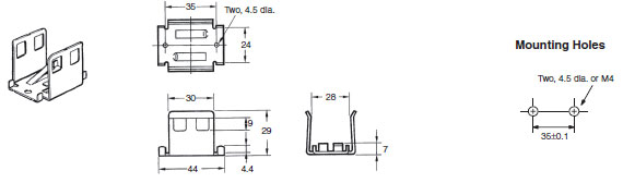
OMRON G7J dimension
G7J Power Relay/Dimensionslast update: November 12, 2012
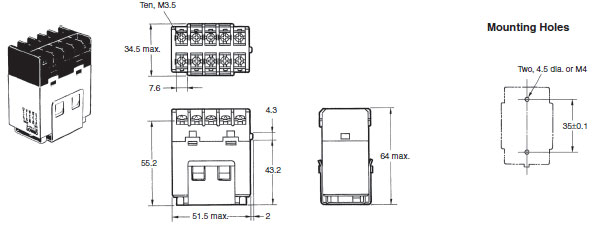
Screw Terminals with W-bracket
G7J-4A-B, G7J-3A1B-B, G7J-3A1B-BZ, G7J-2A2B-B
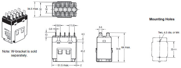
Quick-connect Terminals with W-bracket
G7J-4A-T, G7J-4A-TZ, G7J-3A1B-T, G7J-2A2B-T
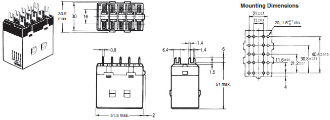
PCB Terminals with PCB Mounting
G7J-4A-P, G7J-4A-PZ, G7J-3A1B-P, G7J-3A1B-PZ, G7J-2A2B-P
Terminal Arrangement/Internal Connections
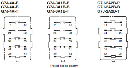
Note: Terminals 43 and 44 of the G7J-4A-P(T) and contacts 41 and 42 of the G7J-3A1B-P(B) are bifurcated contacts.
Accessories (Order Separately)
R99-04 W-bracket (for G5F)
last update: November 12, 2012
- NO. G7J
- TYPE:General Purpose Relays For Built-in Power Relay
- DATE:2021-06-18
- Associated products:
G3S / G3SD Solid State Relays/Features E5CD / E5CD-B Digital Temperature Controller (48 x 48 mm)/Features