OMRON G3TARelays/ Solid-state Relays/Socket / Plug-in Type
OMRON G3TA Relays
OMRON G3TA Dimensions
/Images/l_999-25-118871-198x198.jpglast update: December 19, 2013
• Input and output modules are available in wide variety.
• Snaps easily into P7TF I/O Terminals and can be used together with G7T I/O relays.
• Operation of each SSR can be monitored easily through an LED indicator.
• Models certified for UL and CSA added to the series ("-US" models).
last update: December 19, 2013
Purchase the OMRON Socket / Plug-in Type Please fill in the following
If you have just landed here, this product OMRON G3TA Relays,Relays is offered online by Tianin FLD Technical Co.,Ltd. This is an online store providing Relays at wholesale prices for consumers. You can call us or send enquiry, we would give you the prices, packing,deliverty and more detailed information on the G3TA We cooperate with DHL,TNT,FEDEX,UPS,EMS,etc.They guarantee to meet your needs in terms of time and money,even if you need your OMRON G3TARelays tomorrow morning (aka overnight or next day air) on your desk, 2, 3 days or more.Note to international customers, YES, we ship worldwide.
E2F Resin-case Proximity Sensor/Features
ZAP Pushbutton Switch (Cylindrical 30-dia.)/Features
G3F / G3FD Solid State Relays G3[]-VD/Features
CJ2H-CPU6[]-EIP CJ-series CJ2H (Built-in EtherNet/IP) CPU Units/Features
CPM1A-SRT21 I/O Link Unit/Features
OMRON G3TA specification
G3TA Solid State Relays/Specificationslast update: September 24, 2012
Ratings (at an Ambient Temperature of 25°C)
Input Module
Input
| Model | Rated voltage | Operating voltage | Input current | Voltage level | |
|---|---|---|---|---|---|
| Must operate voltage | Must release voltage | ||||
| G3TA-IAZR02S-US | 100 to 240 VAC | 80 to 264 VAC | 5 mA max. | 80 VAC max. | 10 VAC min. |
| G3TA-IDZR02S-US | 5 to 24 VDC | 4 to 32 VDC | 4 VDC max. | 1 VDC min. | |
| G3TA-IDZR02SM-US | 4 to 24 VDC | 3 to 32 VDC | 3 VDC max. | ||
Output
| Model | Logic level supply voltage | Output breakdown voltage | Output current | Output current (load current) | VCEO (reference value) |
|---|---|---|---|---|---|
| G3TA-IAZR02S-US | 4 to 32 VDC | 32 VDC max. | 25 mA max. | 0.1 to 25 mA | 80 V |
| G3TA-IDZR02S-US | |||||
| G3TA-IDZR02SM-US |
Output Module
Input
| Model | Rated voltage | Operating voltage | Input impedance | Voltage level | |
|---|---|---|---|---|---|
| Must operate voltage | Must release voltage | ||||
| G3TA-OA202SZ-US | 12 VDC | 9.6 to 13.2 VDC | 0.9 kΩ±20% | 9.6 VDC max. | 2 VDC min. |
| 24 VDC | 19.2 to 26.4 VDC | 1.7 kΩ±20% | 19.2 VDC max. | ||
| G3TA-OA202SL-US | 12 VDC | 9.6 to 13.2 VDC | 0.9 kΩ±20% | 9.6 VDC max. | |
| 24 VDC | 19.2 to 26.4 VDC | 1.7 kΩ±20% | 19.2 VDC max. | ||
| G3TA-ODX02S-US | 12 VDC | 9.6 to 13.2 VDC | 3.5 kΩ±20% | 9.6 VDC max. | |
| 24 VDC | 19.2 to 26.4 VDC | 6.5 kΩ±20% | 19.2 VDC max. | ||
| G3TA-OD201S-US | 12 VDC | 9.6 to 13.2 VDC | 3.6 kΩ±20% | 9.6 VDC max. | |
| 24 VDC | 19.2 to 26.4 VDC | 6.4 kΩ±20% | 19.2 VDC max. | ||
Output
| Model | Rated load voltage | Load voltage range | Load current (See note.) | Inrush current | VDRM, VCEO (reference value) |
|---|---|---|---|---|---|
| G3TA-OA202SZ-US | 100 to 240 VAC | 75 to 264 VAC | 0.05 to 2 A | 30 A (60 Hz, 1 cycle) | 600 (VDRM) |
| G3TA-OA202SL-US | 100 to 240 VAC | 75 to 264 VAC | |||
| G3TA-ODX02S-US | 5 to 48 VDC | 4 to 60 VDC | 0.01 to 2 A | 12 A (10 ms) | 80 (VCEO) |
| G3TA-OD201S-US | 48 to 200 VDC | 40 to 200 VDC | 0.01 to 1 A | 6 A (10 ms) | 400 (VCEO) |
Note: The minimum current value is measured at 10°C min.
Characteristics
Input Module
| Item | G3TA-IAZR02S-US | G3TA-IDZR02S-US | G3TA-IDZR02SM-US |
|---|---|---|---|
| Operate time | 20 ms max. | 0.5 ms max. | |
| Release time | 20 ms max. | 0.5 ms max. | |
| Output ON voltage drop | 1.6 V max. | 1.6 V max. | |
| Leakage current | 5 μA max. | ||
| Insulation resistance | 100 MΩ min. (at 500 VDC) | ||
| Dielectric strength | 4,000 VAC, 50/60 Hz for 1 min between input and output | ||
| Vibration resistance | Malfunction: 10 to 55 to 10 Hz, 0.75-mm single amplitude | ||
| Shock resistance | Malfunction: 1,000 m/s2 | ||
| Ambient temperature | Operating: -30°C to 80°C (with no icing or condensation) Storage: -30°C to 100°C (with no icing or condensation) | ||
| Ambient humidity | Operating: 45% to 85% | ||
| Certified standards | UL508 file No. E64562/CSA C22.2 (No. 0, No. 14) file No. LR35535 | ||
| Weight | Approx. 16 g | ||
Output Module
| Certified standards | G3TA-OA202SZ-US | G3TA-OA202SL-US | G3TA-ODX02S-US | G3TA-OD201S-US |
|---|---|---|---|---|
| Operate time | 1/2 of load power source cycle + 1 ms max. | 1 ms max. | 0.5 ms max. | 2 ms max. |
| Release time | 1/2 of load power source cycle + 1 ms max. | 2 ms max. | 2 ms max. | |
| Output ON voltage drop | 1.6 V rms max. | 1.6 V max. | 2.5 V max. | |
| Leakage current | 5 mA max. (at 200 VAC) | 1 mA max. | ||
| Insulation resistance | 100 MΩ min. (at 500 VDC) | |||
| Dielectric strength | 4,000 VAC, 50/60 Hz for 1 min between input and output | |||
| Vibration resistance | Malfunction: 10 to 55 to 10 Hz, 0.75-mm single amplitude | |||
| Shock resistance | Malfunction: 1,000 m/s2 | |||
| Ambient temperature | Operating: -30°C to 80°C (with no icing or condensation) Storage: -30°C to 100°C (with no icing or condensation) | |||
| Ambient humidity | Operating: 45% to 85% | |||
| Certified standards | UL508 file No. E64562, CSA C22.2 (No. 14) file No. LR3553 | |||
| Weight | Approx. 23 g | |||
With up to four G3TA SSRs mounted before G7T Relays, switching is possible at the rated load current for each Relay.
With G3TA SSRs mounted before every other G7T Relays, switching is possible at the rated load current for each Relay.
last update: September 24, 2012
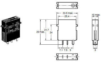
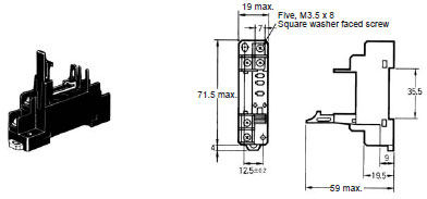
OMRON G3TA dimension
G3TA Solid State Relays/Dimensionslast update: September 24, 2012
G3TA
Connecting Sockets
For Input (NPN, - Common)P7TF-IS16
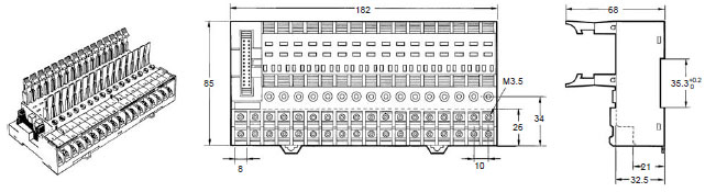
For Output (NPN, + Common)P7TF-OS16
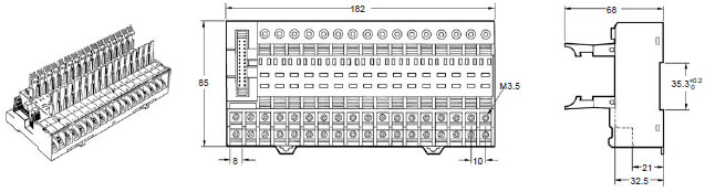
For Output (PNP, + Common)P7TF-OS08
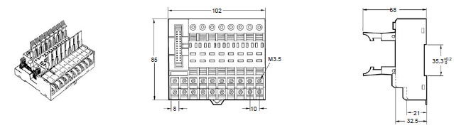
P7TF-O5
last update: September 24, 2012
OMRON G3TA catalog
G3TA Solid State Relays/Catalog- Catalog
- Manual
- CAD
English
Global Edition
| Catalog Name | Catalog Number [size] | Last Update | |
|---|---|---|---|
| | - [865KB] | Jan 15, 201820180115 | G3TA Data Sheet |
OMRON G3TA lineup
G3TA Solid State Relays/Lineuplast update: September 24, 2012
Input Modules
| Isolation | Indicator | Logic level | Rated input voltage | Model | |
|---|---|---|---|---|---|
| Supply voltage | Supply current | ||||
| Photocoupler | Yes | 4 to 32 VDC | 25 mA | 100 to 240 VAC | G3TA-IAZR02S-US |
| 5 to 24 VDC | G3TA-IDZR02S-US | ||||
| No | 4 to 24 VDC | G3TA-IDZR02SM-US | |||
Note: When ordering, specify the rated input voltage.
Output Modules
| Isolation | Zero cross function | Indicator | Rated output load | Rated input voltage | Model |
|---|---|---|---|---|---|
| Phototriac | Yes | Yes | 2 A at 100 to 240 VAC at 60 ° C | 12 VDC | G3TA-OA202SZ-US |
| 24 VDC | |||||
| No | 12 VDC | G3TA-OA202SL-US | |||
| 24 VDC | |||||
| Photocoupler | --- | 2 A at 5 to 48 VDC at 60 ° C | 12 VDC | G3TA-ODX02S-US | |
| 24 VDC | |||||
| 1 A at 48 to 200 VDC at 40 ° C | 12 VDC | G3TA-OD201S-US | |||
| 24 VDC |
Note: 1. For information on products that are certified for international standards, consult your OMRON sales
representatives.
(Models certified for UL and CSA standards have "-US" at the end of the model number.)
2. Input Modules are mainly suitable for signal input to PLCs. For load switching, consider using an Output Module.
I/O Indication
The modules are classified as Input Modules and Output Modules according to the main application of the Module.
I/O module classification and AC/DC use are indicated on the mark affixed to the top of the product.
| Mark indication | Specification |
|---|---|
| AC IN | Input module, AC input |
| DC IN | Input module, DC input |
| AC OUT | Output module, AC output |
| DC OUT | Output module, DC output |
Accessories (Order Separately)
Connecting Socket
| I/O classification | Rated voltage | Model |
|---|---|---|
| Input (NPN, - common) | 12 VDC | P7TF-IS16 |
| 24 VDC | ||
| 100/110 VDC | ||
| 100/110 VAC | ||
| 200/220 VAC | ||
| Output (NPN, + common) | 12 VDC | P7TF-OS16 |
| 24 VDC | ||
| Output (PNP, - common) | 12 VDC | P7TF-OS16-1 |
| 24 VDC | ||
| Output (NPN, + common) | 12 VDC | P7TF-OS08 |
| 24 VDC | ||
| --- | --- | P7TF-05 |
last update: September 24, 2012
- NO. G3TA
- TYPE:Solid-state Relays Socket / Plug-in Type
 Copyright Statement
 - DATE:2021-06-18
- Associated products:
G3H / G3HD Solid State Relays G3[]-VD/Features G3FM Solid State Relays/Features