
OMRON E3C-LDASensors/ Photoelectric Sensors/Separate Amplifier
OMRON E3C-LDA Sensors
- E3C-LDA Photoelectric Sensor with Separate Digital Amplifier (Laser-type)/Catalog
- E3C-LDA Photoelectric Sensor with Separate Digital Amplifier (Laser-type)/Dimensions
- E3C-LDA Photoelectric Sensor with Separate Digital Amplifier (Laser-type)/Lineup
- E3C-LDA Photoelectric Sensor with Separate Digital Amplifier (Laser-type)/Specifications
- Purchase the OMRON E3C-LDA Separate Amplifier
OMRON E3C-LDA Dimensions
/Images/l_1325-25-118723-198x198.jpglast update: May 30, 2013
[Diffuse Reflective Model]
All three beam types provide ample long-distance detection of 1,000 mm.
Three beam types means a wider variety of applications.

[Coaxial Retroreflective Model]
Easy Sensor Installation and Sensing Characteristics Equivalent to Through-beam Sensors.

last update: May 30, 2013
Purchase the OMRON Separate Amplifier Please fill in the following
If you have just landed here, this product OMRON E3C-LDA Sensors,Sensors is offered online by Tianin FLD Technical Co.,Ltd. This is an online store providing Sensors at wholesale prices for consumers. You can call us or send enquiry, we would give you the prices, packing,deliverty and more detailed information on the E3C-LDA We cooperate with DHL,TNT,FEDEX,UPS,EMS,etc.They guarantee to meet your needs in terms of time and money,even if you need your OMRON E3C-LDASensors tomorrow morning (aka overnight or next day air) on your desk, 2, 3 days or more.Note to international customers, YES, we ship worldwide.
G70D-SOC08 Relay Terminal/Features
E2E (Small-diameter) Small-diameter Proximity Sensor/Features
H3YN Solid-state Timer/Features
XS5, XS6 Industrial Ethernet Cables/Features
ZN-CTX / CTM Portable Power Monitor/Features
OMRON E3C-LDA catalog
E3C-LDA Photoelectric Sensor with Separate Digital Amplifier (Laser-type)/Catalog- Catalog
- Manual
- CAD
English
Global Edition
| Catalog Name | Catalog Number [size] | Last Update | |
|---|---|---|---|
| | - [4260KB] | Sep 02, 201520150902 | E3C-LDA Data Sheet |
| | - [465KB] | Jun 01, 201720170601 | E3C-LDA Operating Procedures |
OMRON E3C-LDA dimension
E3C-LDA Photoelectric Sensor with Separate Digital Amplifier (Laser-type)/Dimensionslast update: September 02, 2015
Tolerance class IT16 applies to dimensions in this data sheet unless otherwise specified.
Sensor Head
E3C-LD11
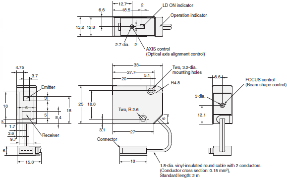
E3C-LD21
E3C-LD31
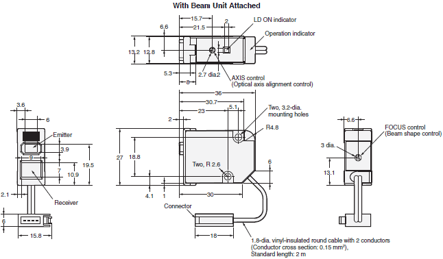
E3C-LR11/-LR12
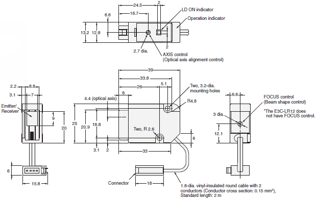
Amplifier Units
Pre-wired Amplifier Units
E3C-LDA11
E3C-LDA21
E3C-LDA41
E3C-LDA51
E3C-LDA11AT
E3C-LDA41AT
E3C-LDA11AN
E3C-LDA41AN
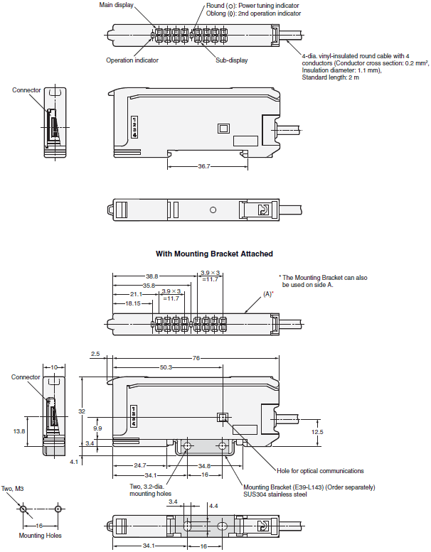
Amplifier Units with Wire-saving Connectors
E3C-LDA6
E3C-LDA7
E3C-LDA8
E3C-LDA9
E3C-LDA6AT
E3C-LDA8AT
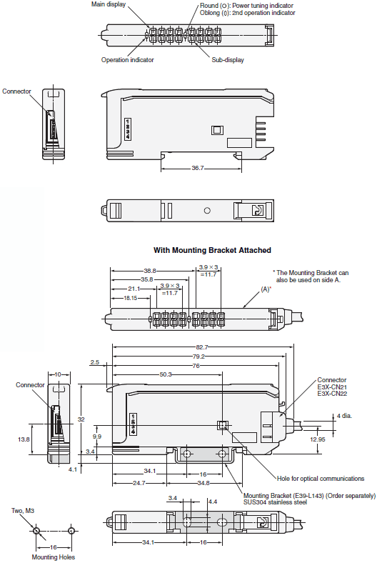
Amplifier Units with Wire-saving Connectors
E3C-LDA6
E3C-LDA7
E3C-LDA8
E3C-LDA9
E3C-LDA6AT
E3C-LDA8AT
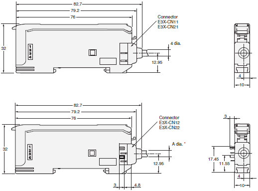
* Cable diameters are as follows:
E3X-CN12 2.6 dia.
E3X-CN22 4.0 dia.
Amplifier Unit with Connector for Sensor Communications Unit
E3C-LDA0
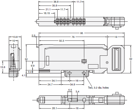
last update: September 02, 2015
OMRON E3C-LDA lineup
E3C-LDA Photoelectric Sensor with Separate Digital Amplifier (Laser-type)/Lineuplast update: May 30, 2013
Sensor Heads
| Sensing method | Appearance | Beam shape | Model | Remarks |
|---|---|---|---|---|
| Diffuse- reflective |  | SpotSpot (variable) | E3C-LD11 2M | Mounting a Beam Unit (sold separately) allows the use of line and area beams. |
 | Line (variable) | E3C-LD21 2M | This model number is for the set consisting of the E39-P11 mounted to the E3C-LD11. | |
| Area (variable) | E3C-LD31 2M | This model number is for the set consisting of the E39-P21 mounted to the E3C-LD11. | ||
| Coaxial Retro-reflective |  | Spot (variable) | E3C-LR11* 2M | Mounting a Beam Unit (order separately) enables the use of line and area beams. |
| Spot (2.0-mm fixed dia.) | E3C-LR12* 2M | --- |
* Select a Reflector (order separately) according to the application.
Amplifier Units
Pre-wired Amplifier Units
| Item | Appearance | Functions | Model | ||
|---|---|---|---|---|---|
| NPN output | PNP output | ||||
| Advanced models | External-input models |  | Remote setting Counter Differential operation | E3C-LDA21 2M | E3C-LDA51 2M |
| Twin-output models | Area output Self-diagnosis Differential operation | E3C-LDA11 2M | E3C-LDA41 2M | ||
| ATC function | ATC (Active Threshold Control) | E3C-LDA11AT 2M | E3C-LDA41AT 2M | ||
| Analog output | Analog output | E3C-LDA11AN 2M | E3C-LDA41AN 2M | ||
Amplifier Units with Wire-saving Connectors
(A Wire-saving Connector (sold separately) is required.)
| Item | Appearance | Functions | Model | ||
|---|---|---|---|---|---|
| NPN output | PNP output | ||||
| Advanced models | External-input models |  | Remote setting Counter Differential operation | E3C-LDA7 * | E3C-LDA9 * |
| Twin-output models | Area output Self-diagnosis Differential operation | E3C-LDA6 * | E3C-LDA8 * | ||
| ATC function | ATC (Active Threshold Control) | E3C-LDA6AT | E3C-LDA8AT | ||
* These models allow you to use an E3X-DRT21-S VER.3 Sensor Communications Unit. When using the E3X-DRT21-S
VER.3, use an E3X-CN02 Connector without a Cable for the Wire-saving Connector.
Amplifier Unit with Connector for Sensor Communications Unit (for EtherCAT and CompoNet)
| Item | Appearance | Functions | Model | Applicable Sensor Communications Unit | |
|---|---|---|---|---|---|
| Advanced models | Twin-output models |  | Area output Self-diagnosis Differential operation | E3C-LDA0 | E3X-ECT |
| E3X-CRT | |||||
Accessories (Order Separately)
Wire-saving connectors (Required for models for Wire-saving Connectors.)
*Protective stickers: provided.
| Item | Appearance | Cable length | No. of conductors | Model |
|---|---|---|---|---|
| Master Connector |  | 2 m | 4 | E3X-CN21 |
| Slave Connector |  | 2 | E3X-CN22 |
Ordering Precaution for Amplifier Units with Wire-saving Connectors
Amplifier Units and Connectors are sold separately. Refer to the following tables when placing an order.
| Amplifier Unit | Applicable Connector (order separately) | |||
|---|---|---|---|---|
| Model | NPN output | PNP output | Master Connector | Slave Connector |
| Advanced models | E3C-LDA6 | E3C-LDA8 | E3X-CN21 | E3X-CN22 |
| E3C-LDA7 | E3C-LDA9 | |||
| E3C-LDA6AT | E3C-LDA8AT | |||
When Using 5 Amplifier Units
| 5 Amplifier Units | + | 1 Master Connector | 4 Slave Connectors |
Mobile Console
| Appearance | Model | Remarks |
|---|---|---|
 | E3X-MC11-SV2 (model number of set) | Mobile Console with Head, Cable, and AC adapter provided as accessories |
 | E3X-MC11-C1-SV2 | Mobile Console |
 | E3X-MC11-H1 | Head |
 | E39-Z12-1 | Cable (1.5 m) |
Note: Use the E3X-MC11-S Mobile Console for the E3X-LDA Series Amplifier Units.
The E3X-MC11-SV2 is an upgraded version of the E3X-MC11-S that is fully interchangeable with the older model.
Refer to E3X-DA-S/MDA for details.
Beam Unit (for E3C-LD11/LR11)
A Beam Unit is not provided with the Sensor and must be ordered separately as required.
| Applicable Sensor Head | Appearance | Focus | Model |
|---|---|---|---|
| E3C-LD11 |  | Line | E39-P11 |
| Area | E39-P21 | ||
| E3C-LR11 |  | Line | E39-P31 |
| Area | E39-P41 |
Reflectors (Required when using retro-reflective models)
A Reflector is not provided with the Sensor head. Be sure to order a Reflector separately.
| Type | Appearance | Model |
|---|---|---|
| Standard Effective area: 23 × 23 mm * |  | E39-R12 |
| Standard Effective area: 7 × 7 mm * |  | E39-R13 |
| Transparent object detection Effective area: 23 × 23 mm * |  | E39-R14 |
| Sheet (cuttable) Effective area: 195 × 22 mm |  | E39-RS4 |
| Sheet (cuttable) Effective area: 108 × 46 mm |  | E39-RS5 |
Note: For details, refer to Reflectors → E39-L/E39-S/E39-R
* Use a standard model (E39-R12/R13) if the distance from the Sensor is 400 mm or more. Use the short-distance
model (E39-R14) if the distance is less than 400 mm.
Mounting Bracket
A Mounting Bracket is not provided with the Amplifier Unit and must be ordered separately as required.
| Appearance | Model | Quantity |
|---|---|---|
 | E39-L143 | 1 |
End Plate
A End Plate is not provided with the Amplifier Unit and must be ordered separately as required.
| Appearance | Model | Quantity |
|---|---|---|
 | PFP-M | 1 |
last update: May 30, 2013
OMRON E3C-LDA specification
E3C-LDA Photoelectric Sensor with Separate Digital Amplifier (Laser-type)/Specificationslast update: September 02, 2015
Sensor Heads
| Item | Diffuse-reflective | Coaxial Retro-reflective (with M.S.R. function) | |||||
|---|---|---|---|---|---|---|---|
| E3C-LD11 | E3C-LD21 | E3C-LD31 | E3C-LR11 | E3C-LR11 + E39-P31 | E3C-LR11 + E39-P41 | E3C-LR12 | |
| Light source (wavelength) | Red semiconductor laser diode (650 nm), 3 mW max. (JIS Class 2, IEC/EN Class 2, and FDA Class 2) | Red semiconductor laser diode (650 nm), 3 mW max. (JIS Class 2, IEC/EN Class 2, and FDA Class 2) | 1 mW max. (JIS Class 1, IEC/EN Class 1, and FDA Class 2) | ||||
| Sensing distance | High-resolution mode: 30 to 1,000 mm Standard mode: 30 to 700 mm Super-high-speed mode: 30 to 250 mm *1 | 7 m 5 m 2 m *2 | 1,700 mm 1,300 mm 700 mm *2 | 900 mm 700 mm 400 mm *2 | 7 m 5 m 2 m *2 | ||
| Focus *3 | 0.8 mm max. (at distances up to 300 mm) | 33 mm (at 150 mm) | 33 × 15 mm (at 150 mm) | 0.8 mm max. (at distances up to 1,000 mm) | 28 mm (at 150 mm) | 28 × 16 mm (at 150 mm) | 2.0-mm dia. (at distance up to 1,000 mm) |
| Functions | Variable focal point mechanism (focus adjustment) *4, optical axis adjustment mechanism (axis adjustment) | ||||||
| Indicators | LDON indicator: Green; Operation indicator: Orange | ||||||
| Ambient illumination (Receiver side) | Incandescent lamp: 3,000 lx | ||||||
| Ambient temperature | Operating: -10 to 55°C, Storage: -25 to 70°C (with no icing or condensation) | ||||||
| Ambient humidity | Operating/storage: 35% to 85% (with no condensation) | ||||||
| Insulation resistance | 20 MΩ min. at 500 VDC | ||||||
| Dielectric strength | 1,000 VAC at 50/60 Hz for 1 minute | ||||||
| Shock resistance | Destruction: 300 m/s2 6 directions 3 times each (up/down, right/left, forward/backward) | ||||||
| Vibration resistance | Destruction: 10 to 150 Hz with double amplitude of 0.7 mm, in X, Y, and Z directions for 80 min each | ||||||
| Degree of protection | IP40 (IEC) | IP40 (IEC 60529) | |||||
| Connection method | Connector (standard cable length: 2 m) | ||||||
| Materials | Case and cover: ABS Front surface filter: Methacrylic resin | Case and cover: ABS Front surface filter: Glass | |||||
| Weight (packed state) | Approx. 85 g | Approx. 100 g | |||||
| Accessories | Instruction manual, Laser warning labels (English) | ||||||
*1. Sensing distance values are for white paper.
*2. These sensing distance values apply when a E39-R12 Reflector is used. The MSR function is built-in. The reflected
light from the object being measured may affect the sensing accuracy, so adjust the threshold value before use.
*3. The beam radius is the value for the middle measurement distance and indicates a typical value for the middle
sensing distance. The radius is defined by light intensity of 1/e2 (13.5%) of the central light intensity.
Light will extend beyond the main beam and may be affected by conditions surrounding the object being measured.
*4. The E3C-LR12 has a fixed beam size (the focal point cannot be changed).
Amplifier Units
| Type | External-input models | Twin-output models | ATC-output models | Analog-output models | |||||
|---|---|---|---|---|---|---|---|---|---|
| Standard models | Standard models | Model for Sensor Commu- nications Unit | Standard models | Standard models | |||||
| Pre- wired | Wire- saving con- nector | Pre- wired | Wire- saving con- nector | Pre- wired | Wire- saving con- nector | Pre-wired | |||
| Model | NPN output | E3C- LDA21 | E3C- LDA7 | E3C- LDA11 | E3C- LDA6 | E3C- LDA0 *1 | E3C- LDA11AT | E3C- LDA6AT | E3C-LDA11AN |
| PNP output | E3C- LDA51 | E3C- LDA9 | E3C- LDA41 | E3C- LDA8 | E3C- LDA41AT | E3C- LDA8AT | E3C-LDA41AN | ||
| Supply voltage | 12 to 24 VDC ±10%, ripple (p-p) 10% max. | ||||||||
| Power consumption | 1,080 mW max. (current consumption: 45 mA max. at power supply voltage of 24 VDC) | ||||||||
| Control output | ON/OFF output | Load power supply voltage: 26.4 VDC max.; NPN/PNP (depends on model) open collector Load current: 50 mA max.; residual voltage: 1 V max. | |||||||
| Analog output | --- | Control output Voltage output: 1 to 5 VDC (connected load 10 kΩ min.) Temperature characteristics 0.3% F.S./°C Response time/ Repeat accuracy Super-high-speed mode: 100 μs/4.0% F.S. High-speed mode: 250 μs/4.0% F.S. Standard mode: 1 ms/2.0% F.S. High-resolution mode: 4 ms/ 2.0% F.S. | |||||||
| Re- sponse time | Super-high- speed mode *2 | 80 μs for operation and reset | 100 μs for operation and reset | --- | 100 μs for operation and reset | ||||
| High-speed mode | 250 μs for operation and reset | ||||||||
| Standard mode | 1 ms for operation and reset | ||||||||
| High- resolution mode | 4 ms for operation and reset | ||||||||
| Func- tions | Differential detection | Switchable between single edge and double edge detection mode. Single edge: Can be set to 250 μs, 500 μs, 1 ms, 10 ms, or 100 ms. Double edge: Can be set to 500 μs, 1 ms, 2 ms, 20 ms, or 200 ms. | --- | ||||||
| Timer function | Select from OFF-delay, ON-delay, or one-shot timer. 1 ms to 5 s (1 to 20 ms set in 1-ms increments, 20 to 200 ms set in 10-ms increments, 200 ms to 1 s set in 100-ms increments, and 1 to 5 s set in 1-s increments) | ||||||||
| Zero-reset | Negative values can be displayed. | ||||||||
| Initial reset | Settings can be returned to defaults as required. | ||||||||
| Mutual interference prevention | Possible for up to 10 Units. *2 | ||||||||
| Counter | Switchable between up counter and down counter. Set count: 0 to 9,999,999 | --- | |||||||
| I/O settings | External input setting (Select from teaching, power tuning, zero reset, light OFF, or counter reset.) | Output setting (Select from channel 2 output, area output, or self-diagnosis.) | Output setting (Select from channel 2 output, area output, self-diagnosis, or ATC error output.) | Analog output setting (Offset voltage can be adjusted.) | |||||
| Digital display | Select from digital incident level + threshold or six other patterns. | ||||||||
| Display orientation | Switching between normal/reversed display is possible. | ||||||||
| Ambient temperature range *3 | Operating: Groups of 1 to 2 Amplifiers: -25°C to 55°C, Groups of 3 to 10 Amplifiers: -25°C to 50°C, Groups of 11 to 16 Amplifiers: -25°C to 45°C Storage: -30°C to 70°C (with no icing) | ||||||||
| Ambient humidity range | Operating and storage: 35% to 85% (with no condensation) | ||||||||
| Insulation resistance | 20 MΩ at 500 VDC | ||||||||
| Dielectric strength | 1,000 VAC at 50/60 Hz for 1 min. | ||||||||
| Vibration resistance *4 | Destruction: 10 to 55 Hz with a 1.5-mm double amplitude for 2 hours each in X, Y, and Z directions | ||||||||
| Shock resistance *5 | Destruction: 500 m/s2, 3 times each in X, Y, and Z directions | ||||||||
| Degree of protection | IP50 (IEC 60529) | ||||||||
| Connection method | Pre-wired or wire-saving connector *6 | ||||||||
| Weight (packed state) | Pre-wired Models: Approx. 100 g Wire-saving Connector Models: Approx. 55 g Sensor Communications Unit Connector Models: Approx. 55 g | ||||||||
| Materi- als | Case | Polybutylene terephthalate (PBT) | |||||||
| Cover | Polycarbonate | ||||||||
*1. This model allows you to use an E3X-ECT EtherCAT Sensor Communications Unit or E3X-CRT CompoNet Sensor
Communications Unit.
*2. Communications are disabled if super-high-speed mode is selected, and the mutual interference prevention function
and the communications function for the Mobile Console will not function.
*3. The following temperature ranges apply when an E3X-ECT EtherCAT or E3X-CRT CompoNet Sensor
Communications Unit is used with the E3C-LDA0: Groups of 1 or 2 Amplifier Units: 0 to 55°C, Groups of 3 to 10
Amplifier Units: 0 to 50°C, Groups of 11 to 16 Amplifier Units: 0 to 45°C, Groups of 17 to 30 Amplifier Units (with the
E3X-ECT): 0 to 40°C.
*4. The vibration resistance of the E3C-LDA0 is as follows: Destruction: 10 to 150 Hz with a 0.7-mm double amplitude for
80 min each in X, Y, and Z directions.
*5. The shock resistance of the E3C-LDA0 is as follows: Destruction: 150 m/s2, 3 times each in X, Y, and Z directions.
*6. A connector for a Sensor Communications Unit is used to connect the E3C-LDA0.
last update: September 02, 2015
- NO. E3C-LDA
- TYPE:Photoelectric Sensors Separate Amplifier
 Copyright Statement
 - DATE:2021-06-07
- Associated products:
E3X-DRT21 / SRT21 / CIF11 Communications Units for E3X-DA-N-series Fiber Amplifiers/Features E3C Compact Head Amplifier-separated Photoelectric Sensor/Features