OMRON E5ARControl Components/ Temperature Controllers/General-purpose
OMRON E5AR Control Components
OMRON E5AR Dimensions
/Images/l_1413-25-118766-198x198.jpglast update: December 19, 2013
• A short sampling period of 50 ms enables use in applications requiring high-speed response.
• PV, SP, and MV data is displayed simultaneously in a 3-row, negative LCD display with a backlight.
• Multiloop control, cascade control, and proportional control are possible with a single Controller.
• When using models with CompoWay/F communications, initial settings can be downloaded and settings can be masked using Support Software (CX-Thermo version 4.0 or higher).
• Equipped with calculation functions as a standard (e.g., square root calculation and broken-line approximation).
• DeviceNet Communications:
Data setting and monitoring can be performed without special programming.
last update: December 19, 2013
Purchase the OMRON General-purpose Please fill in the following
If you have just landed here, this product OMRON E5AR Control Components,Control Components is offered online by Tianin FLD Technical Co.,Ltd. This is an online store providing Control Components at wholesale prices for consumers. You can call us or send enquiry, we would give you the prices, packing,deliverty and more detailed information on the E5AR We cooperate with DHL,TNT,FEDEX,UPS,EMS,etc.They guarantee to meet your needs in terms of time and money,even if you need your OMRON E5ARControl Components tomorrow morning (aka overnight or next day air) on your desk, 2, 3 days or more.Note to international customers, YES, we ship worldwide.
E3S-A Built-in Amplifier Photoelectric Sensor (Medium Size)/Features
D5C Touch Switch/Features
NX-SI / SO Safety I/O Unit/Features
CS1W-CRM21 CS-series CompoNet Master Units/Features
S8M Digital Multicircuit Protector/Features
OMRON E5AR specification
E5AR Digital Controller/Specificationslast update: September 1, 2017
Ratings
| Supply voltage (See note 1.) | 100 to 240 VAC, 50/60 Hz | 24 VAC, 50/60 Hz; 24 VDC | |
|---|---|---|---|
| Operating voltage range | 85% to 110% of rated supply voltage | ||
| Power consumption | 22 VA max. (with maximum load) | 15 VA/10 W max. (with maximum load) | |
| Sensor input (See note 2.) | Thermocouple: K, J, T, E, L, U, N, R, S, B, W Platinum resistance thermometer: Pt100 Current input: 4 to 20 mA DC, 0 to 20 mA DC (including remote SP input) Voltage input: 1 to 5 VDC, 0 to 5 VDC, 0 to 10 VDC (including remote SP input) (Input impedance: 150 Ω for current input, approx. 1 MΩ for voltage input) | ||
| Control output | Voltage (pulse) output | 12 VDC, 40 mA max. with short-circuit protection circuit (E5AR-QQ[]WW-[]: 21 mA max.) | |
| Current output | to 20 mA DC, 4 to 20 mA DC; load: 500 Ω max. (including transfer output) (Resolution: Approx. 54,000 for 0 to 20 mA DC; Approx. 43,000 for 4 to 20 mA DC) | ||
| Relay output | Position-proportional control type (open, closed) N.O., 250 VAC, 1 A (including inrush current) | ||
| Auxiliary output | Relay Output N.O., 250 VAC, 1 A (resistive load) | ||
| Potentiometer input | 100 Ω to 2.5 kΩ | ||
| Event input | Contact | Input ON: 1 kΩ max.; OFF: 100 kΩ min. | |
| No-contact | Input ON: Residual voltage of 1.5 V max.; OFF: Leakage current of 0.1 mA max. | ||
| Short circuit current: Approx. 4 mA | |||
| Remote SP input | Refer to the information on sensor input. | ||
| Transfer output | Refer to the information on control output. | ||
| Control method | 2-PID or ON/OFF control | ||
| Setting method | Digital setting using front panel keys or setting using serial communications | ||
| Indication method | 7-segment digital display and single-lighting indicator Character Height PV: 12.8 mm; SV: 7.7 mm; MV: 7.7 mm | ||
| Other functions | Depends on model. | ||
| Ambient operating temperature | -10 to 55°C (with no icing or condensation) For 3 years of assured use: -10 to 50°C (with no icing or condensation) | ||
| Ambient operating humidity | 25% to 85% | ||
| Storage temperature | -25 to 65°C (with no icing or condensation) | ||
Note 1: The supply voltage (i.e., 100 to 240 VAC or 24 VAC/VDC) depends on the model. Be sure to specify the required
type when ordering.
2: The Controller is equipped with multiple sensor input. Temperature input or analog input can be selected with the
input type setting switch. There is basic insulation between power supply and input terminals, power supply and
output terminals, and input and output terminals.
3: Do not use an inverter output as the power supply. (Refer to Safety Precautions for All E5[]R Models.)
Input Ranges
Platinum Resistance Thermometer, Thermocouple, Current, or Voltage Input
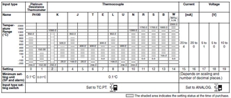
Characteristics
| Indication accuracy | Thermocouple input with cold junction compensation: (±0.1% of PV or ±1°C, whichever is greater) ±1 digit max. (See note 1.) Thermocouple input without cold junction compensation: (±0.1% FS or ±1°C, whichever is smaller) ±1 digit (See note 2.) Analog input: ±0.1% FS ±1 digit max. Platinum resistance thermometer input: (±0.1% of PV or ±0.5°C, whichever is greater) ±1 digit max. Position-proportional potentiometer input: ±5% FS ±1 digit max. |
|---|---|
| Control mode | Standard control (heating or cooling control), heating/cooling control, standard control with remote SP (2-input models only), heating/cooling control with remote SP (2-input models only), cascade standard control (2-input models only), cascade heating/cooling control (2-input models only), proportional control (2-input models only), position-proportional control (control-valve control models only) |
| Influence of temperature | Thermocouple input (R, S, B, W): (±1% of PV or ±10°C, whichever is greater) ±1 digit max. Other thermocouple input: (±1% of PV or ±4°C, whichever is greater) ±1 digit max. *K thermocouple at -100°C max.: ±10°C max. Platinum resistance thermometer: (±1% of PV or ±2°C, whichever is greater) ±1 digit max. Analog input: (±1%FS) ±1 digit max. |
| Influence of voltage | |
| Influence of EMS. (at EN61326-1) | |
| Control period | 0.2 to 99.0 s (in units of 0.1 s) for time-proportioning control output |
| Proportional band (P) | 0.00% to 999.99% FS (in units of 0.01% FS) |
| Integral time (I) | 0.0 to 3,999.9 s (in units of 0.1 s) |
| Derivative time (D) | 0.0 to 3,999.9 s (in units of 0.1 s) |
| Hysteresis | 0.01% to 99.99% FS (in units of 0.01% FS) |
| Manual reset value | 0.0% to 100.0% (in units of 0.1% FS) |
| Alarm setting range | -19,999 to 99,999 EU (See note 3.) (The decimal point position depends on the input type and the decimal point position setting.) |
| Input sampling period | 50 ms |
| Insulation resistance | 20 MΩ min. (at 500 VDC) |
| Dielectric strength | 2,000 VAC, 50/60 Hz for 1 min (between charged terminals of different polarities) |
| Vibration resistance | 10 to 55 Hz, 20 m/s2 for 10 min each in X, Y, and Z directions |
| Shock resistance | 100 m/s2, 3 times each in X, Y, and Z directions |
| Inrush current | 100 to 240-VAC models: 50 A max. 24 VAC/VDC models: 30 A max. |
| Weight | Controller only: Approx. 450 g; Mounting bracket: Approx. 60 g; Terminal cover: Approx. 30 g |
| Degree of protection | Front panel: NEMA4X for indoor use (equivalent to IP66); Rear case: IP20; Terminals: IP00 |
| Memory protection | Non-volatile memory (number of writes: 100,000) |
| Applicable standards | UL61010C-1, CSA C22.2 No. 1010-1 EN61010-1 (IEC61010-1): Pollution degree 2/overvoltage category 2 |
| EMC | EMI: EN61326-1 (See note 5.) Radiated Interference Electromagnetic Field Strength: EN55011 Group 1 Class A Noise Terminal Voltage: EN55011 Group 1 Class A EMS: EN61326-1 (See note 5.) ESD Immunity: EN61000-4-2: 4 kV contact discharge (level 2) 8 kV air discharge (level 3) Electromagnetic Immunity: EN61000-4-3: 10 V/m (amplitude-modulated, 80 MHz to 1 GHz, 1.4 GHz to 2 GHz) (level 3) Burst Noise Immunity: EN61000-4-4: 2 kV power line (level 3) 2 kV output line (relay output) (level 4) 1 kV measurement line, I/O signal line (level 4) 1 kV communications line (level 3) Conducted Disturbance Immunity: EN61000-4-6: 3 V (0.15 to 80 MHz) (level 3) Surge Immunity: EN61000-4-5: 1 kV line to line (power line, output line (relay output)) (level 2) 2 kV line to ground (power line, output line (relay output)) (level 3) Power Frequency Magnetic Field Immunity: EN61000-4-8: 30 A/m (50 Hz) continuous field Voltage Dip/Interrupting Immunity: EN61000-4-11: 0.5 cycle, 100% (rated voltage) |
Note 1: K-, T-, or N-type thermocouple at −100°C max.: ±2°C ±1 digit max.
U- or L-type thermocouple: ±2°C ±1 digit max.
B-type thermocouple at 400°C max.: No accuracy specification.
R- or S-type thermocouple at 200°C max.: ±3°C ±1 digit max.
W-type thermocouple: (±0.3% of PV or ±3°C, whichever is greater) ±1 digit max.
2: U- or L-type thermocouple: ±1°C ±1 digit
R- or S-type thermocouple at 200°C max.: ±1.5°C ±1 digit
3: "EU" (Engineering Unit) represents the unit after scaling. If a temperature sensor is used it is either °C or °F.
4: Conditions: Ambient temperature from −10 to 23 to 55°C and voltage of −15% to 10% of rated voltage.
5: Industrial electromagnetic environment (EN/IEC 61326-1 Table 2)
Communications Specifications
| Transmission path connection | Multiple points |
|---|---|
| Communications method | RS-485 (two-wire, half duplex) |
| Synchronization method | Start-stop synchronization |
| Baud rate | 9,600, 19,200, or 384,000 bps |
| Transmission code | ASCII |
| Data bit length | 7 or 8 bits |
| Stop bit length | 1 or 2 bits |
| Error detection | Vertical parity (none, even, odd) Block check character (BCC): CompoWay/F CRC-16: Modbus |
| Flow control | None |
| Interface | RS-485 |
| Retry function | None |
| Communications buffer | 217 bytes |
| Communications response send wait time | 0 to 99 ms, Default: 20 ms |
DeviceNet
| Item | Specifications | ||||
|---|---|---|---|---|---|
| Communications protocol | Conforms to DeviceNet | ||||
| Communications functions | Remote I/O communications | • Master-slave connections (polling, bit-strobe, COS, or cyclic) • Conform to DeviceNet specifications. | |||
| I/O allocations | • Can allocate any I/O data from the Configurator. • Can allocate any data, such as parameters specific to the DeviceNet and the Digital Controller variable area. • Up to 2 blocks for the IN Area, up to a total of 100 words. • One block for the OUT Area, up to 100 words (first word is always allocated to Output Enable Bits). | ||||
| Message communications | • Explicit message communications • CompoWay/F communications commands can be sent (commands are sent in explicit message format). | ||||
| Connection format | Combination of multidrop and T-branch connections (for trunk and drop lines) | ||||
| Baud rate | DeviceNet: 500, 250, or 125 kbps, or automatic detection of master baud rate | ||||
| Communications media | Special 5-wire cable (2 signal lines, 2 power lines, and 1 shield line) | ||||
| Communications distance | Baud rate | Network length | Drop line length | Total drop line length | |
| 500 kbps | 100 m max. (100 m max.) | 6 m max. | 39 m max. | ||
| 250 kbps | 250 m max. (100 m max.) | 6 m max. | 78 m max. | ||
| 125 kbps | 500 m max. (100 m max.) | 6 m max. | 156 m max. | ||
| The values in parentheses apply when Thin Cables are used. | |||||
| Supply voltage | DeviceNet power supply: 24 VDC | ||||
| Allowable voltage range | DeviceNet power supply: 11 to 25 VDC | ||||
| Current consumption | 50 mA max. (24 VDC) | ||||
| Maximum number of nodes that can be connected | 64 (includes Configurator when used) | ||||
| Maximum number of slaves that can be connected | 63 | ||||
| Error control | CRC error detection | ||||
| Power supply | Power supplied from DeviceNet communications connector. | ||||
last update: September 1, 2017
OMRON E5AR lineup
E5AR Digital Controller/Lineuplast update: September 15, 2016
Digital Controllers (When your order, specify the power supply voltage.)
Standard Controllers (100 to 240 VAC)
| Size | Control type | Control mode | Outputs (control/ transfer) | Optional functions | Model | ||
|---|---|---|---|---|---|---|---|
| Auxiliary outputs (SUB) | Event inputs | Serial com- muni- cations | |||||
| 96 × 96 mm | Basic control (1 loop) | Single-loop standard control Single-loop heating and cooling control | 2 points: Pulse voltage and Pulse voltage/current | 4 | 2 | No | E5AR-Q4B |
| 2 points: Current and Current | E5AR-C4B | ||||||
| 2 points: Pulse voltage and Pulse voltage/current | RS-485 | E5AR-Q43B-FLK | |||||
| 2 points: Current and Current | E5AR-C43B-FLK | ||||||
| 2 points: Pulse voltage and Pulse voltage/current | 6 | E5AR-Q43DB-FLK | |||||
| 2 points: Current and Current | E5AR-C43DB-FLK | ||||||
| 4 points: Pulse voltage and Pulse voltage/current and Current (2 points) | E5AR-QC43DB-FLK | ||||||
| 2-loop control | 2-loop standard control Single-loop heating and cooling control Single-loop cascade control Single-loop control with remote SP Single-loop proportional control | 2 points: Pulse voltage and Pulse voltage/current | 4 | 4 | RS-485 | E5AR-Q43DW-FLK | |
| 2 points: Current and Current | E5AR-C43DW-FLK | ||||||
| 2-loop standard control 2-loop heating and cooling control Single-loop cascade control Single-loop control with remote SP Single-loop proportional control | 4 points: Pulse voltage (2 points) and Pulse voltage/ current (2 points) | E5AR-QQ43DW-FLK | |||||
| 4-loop control | 4-loop standard control 2-loop heating and cooling control | 4 points: Current output (4 points) | 4 | 4 | RS-485 | E5AR-CC43DWW-FLK | |
| 4 points: Pulse voltage (2 points) and Pulse voltage/ current (2 points) | E5AR-QQ43DWW-FLK | ||||||
| Position- pro- portional control (1 loop) | 4-loop standard control 2-loop heating and cooling control | Relay output (1 open, 1 close) | 4 | 4 | No | E5AR-PR4DF | |
| Relay output (1 open, 1 close) and 1 current (transfer) output | RS-485 | E5AR-PRQ43DF-FLK | |||||
Note: Can be switched between close control and floating control.
Standard Controllers (24 VAC/DC)
| Size | Control type | Control mode | Outputs (control/ transfer) | Optional functions | Model | ||
|---|---|---|---|---|---|---|---|
| Auxiliary outputs (SUB) | Event inputs | Serial com- muni- cations | |||||
| 96 × 96 mm | Basic control (1 loop) | Single-loop standard control Single-loop heating and cooling control | 2 points: Pulse voltage and Pulse voltage/ current | 4 | 2 | No | E5AR-Q4B |
| 2 points: Current and Current | E5AR-C4B | ||||||
| 4 points: Pulse voltage and Pulse voltage/ current and Current (2 points) | 6 | RS-485 | E5AR-QC43DB-FLK | ||||
| 2-loop control | 2-loop standard control 2-loop heating and cooling control Single-loop cascade control Single-loop control with remote SP Single-loop proportional control | 4 points: Pulse voltage (2 points) and Pulse voltage/current (2 points) | 4 | 4 | RS-485 | E5AR-QQ43DW-FLK | |
| 4-loop control | 4-loop standard control 2-loop heating and cooling control | 4 points: Current output (4 points) | 4 | 4 | RS-485 | E5AR-CC43DWW-FLK | |
| Position- pro- portional control (1 loop) | Single-loop position- proportional control (See note.) | Relay output (1 open, 1 close) | 4 | 4 | No | E5AR-PR4DF | |
| Relay output (1 open, 1 close) and 1 current (transfer) output | RS-485 | E5AR-PRQ43DF-FLK | |||||
Note: Can be switched between close control and floating control.
DeviceNet-compatible Controllers (100 to 240 VAC)
| Size | Control type | Control mode | Outputs (control/ transfer) | Optional functions | Model | ||
|---|---|---|---|---|---|---|---|
| Auxiliary outputs (SUB) | Event inputs | DeviceNet communi- cations | |||||
| 96 × 96 mm | Basic control (1 loop) | 1 loop for standard control Single-loop heating and cooling control | 2 points: Pulse voltage and Pulse voltage/current | 4 | 2 | Yes | E5AR-Q4B-DRT |
| 2 points: Current and Current | E5AR-C4B-DRT | ||||||
| 4 points: Pulse voltage and Pulse voltage/current and Current (2 points) | E5AR-QC4B-DRT | ||||||
| 2-loop control | 2-loop standard control 2-loop heating and cooling control Single-loop cascade control Single-loop control with remote SP Single-loop proportional control | 4 points: Pulse voltage (2 points) and Pulse voltage/ current (2 points) | 4 | None | Yes | E5AR-QQ4W-DRT | |
| 4-loop control | 4-loop standard control 2-loop heating and cooling control | 4 points: Current (4 points) | 4 | None | Yes | E5AR-CC4WW-DRT | |
| Position- pro- portional control (1 loop) | Single-loop position- proportional control (See note.) | Relay output (1 open, 1 close) | 4 | None | Yes | E5AR-PR4F-DRT | |
| Relay output (1 open, 1 close) and 1 current (transfer) output | E5AR-PRQ4F-DRT | ||||||
Note: Can be switched between close control and floating control.
DeviceNet-compatible Controllers (24 VAC/DC)
| Size | Control type | Control mode | Outputs (control/ transfer) | Optional functions | Model | ||
|---|---|---|---|---|---|---|---|
| Auxiliary outputs (SUB) | Event inputs | DeviceNet communi- cations | |||||
| 96 × 96 mm | Basic control (1 loop) | 1 loop for standard control Single-loop heating and cooling control | 2 points: Pulse voltage and Pulse voltage/current | 4 | 2 | Yes | E5AR-Q4B-DRT |
| 2 points: Current and Current | E5AR-C4B-DRT | ||||||
| 4 points: Pulse voltage and Pulse voltage/current and Current (2 points) | E5AR-QC4B-DRT | ||||||
| 2-loop control | 2-loop standard control 2-loop heating and cooling control Single-loop cascade control Single-loop control with remote SP Single-loop proportional control | 4 points: Pulse voltage (2 points) and Pulse voltage/ current (2 points) | 4 | None | Yes | E5AR-QQ4W-DRT | |
| 4-loop control | 4-loop standard control 2-loop heating and cooling control | 4 points: Current (4 points) | 4 | None | Yes | E5AR-CC4WW-DRT | |
| Position- pro- portional control (1 loop) | Single-loop position- proportional control (See note.) | Relay output (1 open, 1 close) | 4 | None | Yes | E5AR-PR4F-DRT | |
| Relay output (1 open, 1 close) and 1 current (transfer) output | E5AR-PRQ4F-DRT | ||||||
Note: Can be switched between close control and floating control.
Inspection Results
The Inspection Report can be ordered at the same time as the Digital Controller using the following model number.
Inspection Report (Sold Separately)
| Descriptions | Model |
|---|---|
| Inspection Report for E5AR | E5AR-K |
Accessories (Order Separately)
Terminal Cover (Sold Separately)
| Descriptions | Model |
|---|---|
| Terminal Cover for E5AR | E53-COV14 |
Unit Label Sheet
| Model |
|---|
| Y92S-L1 |
Rubber Packing
| Model |
|---|
| Y92S-P4 |
Note: The Rubber Packing is provided with the Digital Controller.
Mounting Adapters
| Model |
|---|
| Y92H-9 |
Note: These Mounting Adapters are provided with the Digital Controller.
last update: September 15, 2016
OMRON E5AR catalog
E5AR Digital Controller/Catalog- Catalog
- Manual
- CAD
English
Global Edition
| Catalog Name | Catalog Number [size] | Last Update | |
|---|---|---|---|
| | - [2047KB] | Sep 01, 201720170901 | E5AR Data Sheet |
OMRON E5AR dimension
E5AR Digital Controller/Dimensionslast update: September 15, 2016
E5AR
• Recommended panel thickness is 1 to 8 mm.
• Group mounting is not possible. (Maintain the specified mounting space between Controllers.)
• When two or more Controllers are mounted, make sure that the surrounding temperature does not exceed the allowable
operating temperature specified in the specifications.
Accessories (Order Separately)
Terminal Cover
E53-COV14 (for E5AR)
Unit Label Sheet
Y92S-L1
Rubber Packing
Y92S-P4 (for DIN96 × 96)
Order the Rubber Packing separately if it becomes lost or damaged. (Refer to Data Sheet.)
The Rubber Packing can be used to achieve an IP66 degree of protection.
(Deterioration, shrinking, or hardening of the rubber packing may occur depending on the operating environment. Therefore, periodic replacement is recommended to ensure the level of waterproofing specified in NEMA4. The time for periodic replacement depends on the operating environment. Be sure to confirm this point at your site. Consider one year a rough standard. OMRON shall not be liable for the level of water resistance if the customer does not perform periodic replacement.)
The Rubber Packing does not need to be attached if a waterproof structure is not required.
Mounting Adapters
Y92H-9 (2pcs)
One set is packaged with the product.
Order Mounting Adapters separately if yours are lost or damaged.
last update: September 15, 2016
- NO. E5AR
- TYPE:Temperature Controllers General-purpose
 Copyright Statement
 - DATE:2021-06-07
- Associated products:
E5AN-H, E5EN-H Advanced Digital Temperature Controller (96 x 96 mm and 48 x 96 mm)/Features E5ER Digital Controllers/Features