OMRON E3S-ASensors/ Photoelectric Sensors/Built-in Amplifier
OMRON E3S-A Sensors
- E3S-A Built-in Amplifier Photoelectric Sensor (Medium Size)/Catalog
- E3S-A Built-in Amplifier Photoelectric Sensor (Medium Size)/Lineup
- E3S-A Built-in Amplifier Photoelectric Sensor (Medium Size)/Dimensions
- E3S-A Built-in Amplifier Photoelectric Sensor (Medium Size)/Specifications
- Purchase the OMRON E3S-A Built-in Amplifier
OMRON E3S-A Dimensions
/Images/l_410-25-118729-198x198.jpglast update: December 19, 2013
No information is provided on the features of this product.
last update: December 19, 2013
Purchase the OMRON Built-in Amplifier Please fill in the following
If you have just landed here, this product OMRON E3S-A Sensors,Sensors is offered online by Tianin FLD Technical Co.,Ltd. This is an online store providing Sensors at wholesale prices for consumers. You can call us or send enquiry, we would give you the prices, packing,deliverty and more detailed information on the E3S-A We cooperate with DHL,TNT,FEDEX,UPS,EMS,etc.They guarantee to meet your needs in terms of time and money,even if you need your OMRON E3S-ASensors tomorrow morning (aka overnight or next day air) on your desk, 2, 3 days or more.Note to international customers, YES, we ship worldwide.
R88M-K, R88D-KN[]-ML2 G5-series AC Servomotors/Servo Drives with Built-in MECHATROLINK-II Communi...
G70D-SOC08 Relay Terminal/Features
E3S-DB Transparent Object Detection Photoelectric Sensor/Features
E2FM Proximity Sensor with All-stainless Housing/Features
H3DK-G Star-delta Timer/Features
OMRON E3S-A catalog
E3S-A Built-in Amplifier Photoelectric Sensor (Medium Size)/Catalog- Catalog
- Manual
- CAD
English
Global Edition
| Catalog Name | Catalog Number [size] | Last Update | |
|---|---|---|---|
| | - [4435KB] | Jul 12, 201720170712 | E3S-A Data Sheet |
OMRON E3S-A lineup
E3S-A Built-in Amplifier Photoelectric Sensor (Medium Size)/Lineuplast update: July 12, 2017
Built-in Amplifier Photoelectric Sensors
| Sensing method | Appearance | Connection method | Sensing distance | Functions | Model | |
|---|---|---|---|---|---|---|
| NPN output | PNP output | |||||
| Through- beam Sensors *1 | Horizontal | Pre-wired | 7 m (Red light) | --- | E3S-AT11 2M Emitter E3S-AT11-L Receiver E3S-AT11-D | E3S-AT31 2M Emitter E3S-AT31-L Receiver E3S-AT31-D |
 | E3S-AT21 2M Emitter E3S-AT21-L Receiver E3S-AT21-D | E3S-AT41 2M Emitter E3S-AT41-L Receiver E3S-AT41-D | ||||
| Connector (M12) | --- | E3S-AT16 Emitter E3S-AT16-L Receiver E3S-AT16-D | E3S-AT36 Emitter E3S-AT36-L Receiver E3S-AT36-D | |||
Vertical | Pre-wired | --- | E3S-AT61 2M Emitter E3S-AT61-L Receiver E3S-AT61-D | E3S-AT81 2M Emitter E3S-AT81-L Receiver E3S-AT81-D | ||
| E3S-AT71 2M Emitter E3S-AT71-L Receiver E3S-AT71-D | E3S-AT91 2M Emitter E3S-AT91-L Receiver E3S-AT91-D | ||||
| Connector (M12) | --- | E3S-AT66 Emitter E3S-AT66-L Receiver E3S-AT66-D | E3S-AT86 Emitter E3S-AT86-L Receiver E3S-AT86-D | |||
| Retro- reflective Sensors | Horizontal | Pre-wired | 2 m (100 mm) *2 (Red light) | --- | E3S-AR11 2M | E3S-AR31 2M |
| E3S-AR21 2M | E3S-AR41 2M | ||||
| Connector (M12) | --- | E3S-AR16 | E3S-AR36 | |||
Vertical | Pre-wired | --- | E3S-AR61 2M | E3S-AR81 2M | ||
| E3S-AR71 2M | E3S-AR91 2M | ||||
| Connector (M12) | --- | E3S-AR66 | E3S-AR86 | |||
| Diffuse- reflective Sensors | Horizontal | Pre-wired | 100 mm (wide view) (Infrared light) | --- | E3S-AD13 2M | E3S-AD33 2M |
 | E3S-AD23 2M | E3S-AD43 2M | ||||
| 200 mm (Red light) | --- | E3S-AD11 2M | E3S-AD31 2M | |||
 | E3S-AD21 2M | E3S-AD41 2M | ||||
| 700 mm (Infrared light) | --- | E3S-AD12 2M | E3S-AD32 2M | |||
| E3S-AD22 2M | E3S-AD42 2M | ||||
| Connector (M12) | 100 mm (wide view) (Infrared light) | --- | E3S-AD18 | E3S-AD38 | ||
| 200 mm (Red light) | E3S-AD16 | E3S-AD36 | ||||
| 700 mm (Infrared light) | E3S-AD17 | E3S-AD37 | ||||
Vertical | Pre-wired | 100 mm (wide view) (Infrared light) | --- | E3S-AD63 2M | E3S-AD83 2M | |
| E3S-AD73 2M | E3S-AD93 2M | ||||
| 200 mm (Red light) | --- | E3S-AD61 2M | E3S-AD81 2M | |||
| E3S-AD71 2M | E3S-AD91 2M | ||||
| 700 mm (Infrared light) | --- | E3S-AD62 2M | E3S-AD82 2M | |||
| E3S-AD72 2M | E3S-AD92 2M | ||||
| Connector (M12) | 100 mm (wide view) (Infrared light) | --- | E3S-AD68 | E3S-AD88 | ||
| 200 mm (Red light) | E3S-AD66 | E3S-AD86 | ||||
| 700 mm (Infrared light) | E3S-AD67 | E3S-AD87 | ||||
*1. Through-beam Sensors are normally sold in sets that include both the Emitter and Receiver. Orders for individual Emitters and Receivers are accepted.
*2. Values in brackets are the minimum required distance between the Sensor and Reflector.
Accessories (Order Separately)
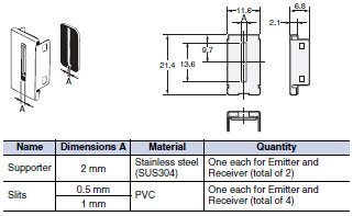
Insert-type Long Slit
| Name | Slit width | Sensing distance | Minimum sensing object (typical) | Model | Quantity | Remarks |
|---|---|---|---|---|---|---|
| Slits | 0.5 mm × 11.1 mm | 500 mm | 0.2-mm dia. | E39-S46 | 1 of each for Emitter/ Receiver (4 Slits total) | Slits can be used with the E3S-AT[][] Through-beam Sensor. |
| 1 mm × 11.1 mm | 1.1 m | 0.4-mm dia. | ||||
| Supporter | 2 mm × 13.6 mm | 2.5 m | 0.8-mm dia. | 1 of each for Emitter/ Receiver (2 Slits total) |
Mutual Interference Prevention Filters
| Sensing distance | Model | Quantity | Remarks |
|---|---|---|---|
| 2.4 m | E39-E6 | 2 of each for Emitter/Receiver (4 Filters total) | Can be used with the E3S-AT[][] Through-beam Sensor. |
Reflectors/Other Accessories
| Name | Sensing distance (typical) | Model | Quantity | Remarks |
|---|---|---|---|---|
| Reflectors | 2 m (100 mm) * (rated value) | E39-R1 | 1 | Provided with E3S-AR[][] Retro-reflective Sensor. |
| Small Reflectors | 1.3 m (100 mm) * | E39-R3 | 1 | --- |
| 600 mm (70 mm) * | E39-R4 | 1 | --- | |
| Tape Reflectors | 450 mm (100 mm) * | E39-RS1 | 1 | Enables MSR function. |
| 700 mm (100 mm) * | E39-RS2 | 1 | ||
| 900 mm (100 mm) * | E39-RS3 | 1 | ||
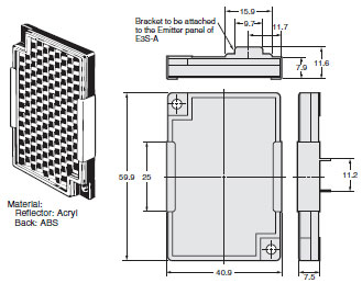
| Optical Axis Confirmation Reflector | --- | E39-R5 | 1 | Used to check optical axis for the E3S-AT[][] Through-beam Sensor. |
Note: When using any Reflector other than the provided one, use a sensing distance of approximately 0.7 times the typical value as a guide.
*Values in brackets are the minimum required distance between the Sensor and Reflector.
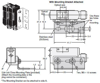
Mounting Brackets/Other
Some Mounting Brackets are provided with the Sensor. Order other Mounting Brackets separately if required.
| Appearance | Model | Quantity | Remarks |
|---|---|---|---|
 | E39-L69 | 1 | Provided with E3S-A Horizontal Sensors. Two Brackets are provided with a Through-beam Sensor. |
 | E39-L70 | 1 | Provided with E3S-A Vertical Sensors. Two Brackets are provided with a Through-beam Sensor. |
 | E39-L59 | 1 | Provided with E3S-A Vertical Pre-wired Sensors. |
 | E39-L81 | 1 | Provided with E3S-A Vertical Connector Sensors. |
 | E39-L97 *1 | 1 | Protective Cover for Horizontal Sensors |
 | E39-L98 *2 | 1 | Protective Cover for Vertical Sensors |
 | E39-L60 | 1 | Close Mounting Plate: Provided with E3S-A Connector Sensors. Two Plates are provided with a Through-beam Sensor. |
Note: If a Through-beam Model is used, order two Mounting Brackets, one for the Emitter and one for the Receiver.
*1. Mount a Sensor with a Connector carefully because the Sensor I/O Connector will come into contact with the Mounting Bracket or Mounting Plate.
*2. Usage is not possible with Sensors with Connectors.
Sensors I/O Connectors
| Model | Quantity | Remarks |
|---|---|---|
| E39-G2 | 1 | Provided with product. |
Sensors I/O Connectors
| Cable | Appearance | Cable type | Model | ||
|---|---|---|---|---|---|
| Standard | Straight |  | 2 m | 3-wire | XS2F-D421-DC0-F |
| 5 m | XS2F-D421-GC0-F | ||||
| L-shaped |  | 2 m | XS2F-D422-DC0-F | ||
| 5 m | XS2F-D422-GC0-F | ||||
Note: When using Through-beam models, order one connector for the Receiver and one for the Emitter.
last update: July 12, 2017
OMRON E3S-A dimension
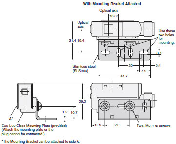
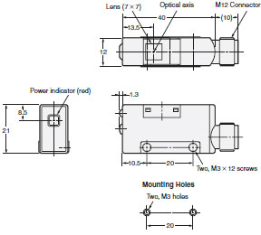
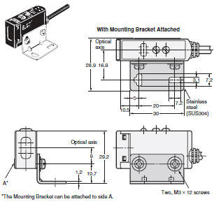
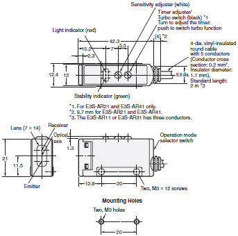
E3S-A Built-in Amplifier Photoelectric Sensor (Medium Size)/Dimensionslast update: February 3, 2016
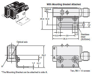
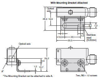
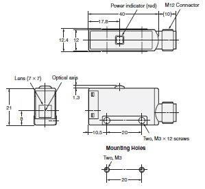
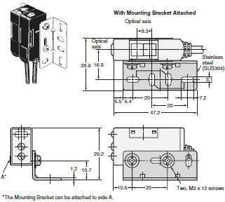
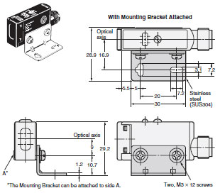
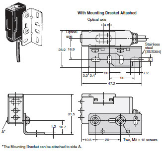
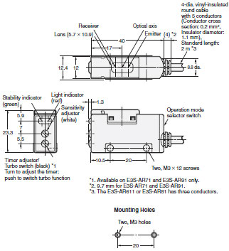
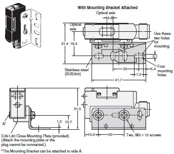
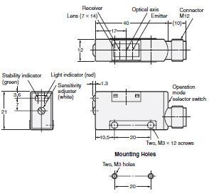
(Unit: mm)
E3S-A Built-in Amplifier Photoelectric Sensor
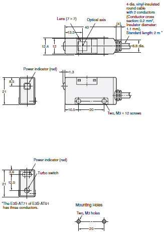
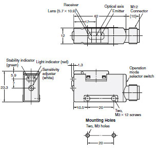
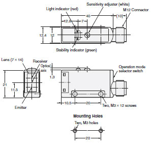
Through-beam Sensors (Horizontal)
Pre-wired Sensors
E3S-AT11/21/31/41 (Receiver)
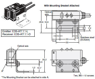
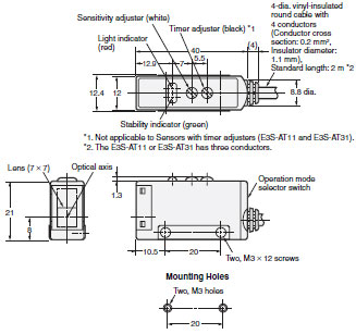
E3S-AT11/31 (Emitter)
E3S-AT21/41(Emitter)
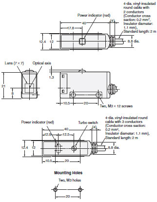
Note:Models numbers for Through-beam Sensors (E3S-AT[]1) are for sets that include both the Emitter and Receiver.
The model number of the Emitter is expressed by adding "-L" to the set model number (example: E3S-AT11-L 2M), the model number of the Receiver, by adding "-D" (example: E3S-AT11-D 2M). Refer to Lineup to confirm model numbers for Emitter and Receivers.
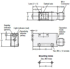
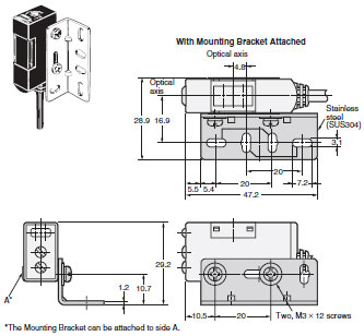
Sensors with Standard Connectors
E3S-AT16/36 (Receiver)
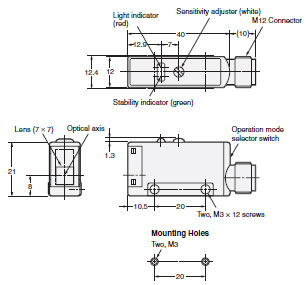
E3S-AT16/36 (Emitter)
Note: Models numbers for Through-beam Sensors (E3S-AT[]6) are for sets that include both the Emitter and Receiver.
The model number of the Emitter is expressed by adding "-L" to the set model number (example: E3S-AT16-L),
the model number of the Receiver, by adding "-D" (example: E3S-AT16-D). Refer to Ordering Information to
confirm model numbers for Emitter and Receivers.
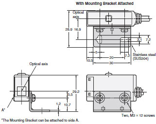
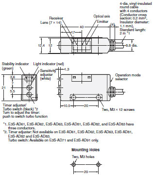
Through-beam Sensors (Vertical)
Pre-wired Sensors
E3S-AT61/71/81/91 (Receiver)
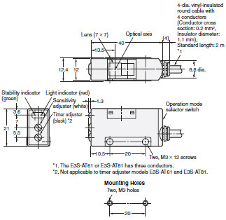
E3S-AT61/81 (Emitter)
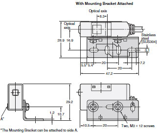
E3S-AT71/91 (Emitter)
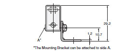
Note:Models numbers for Through-beam Sensors (E3S-AT[]1) are for sets that include both the Emitter and Receiver.
The model number of the Emitter is expressed by adding "-L" to the set model number (example: E3S-AT61-L 2M), the model number of the Receiver, by adding "-D" (example: E3S-AT61-D 2M). Refer to Lineup to confirm model numbers for Emitter and Receivers.
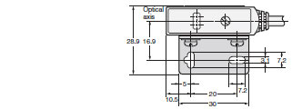
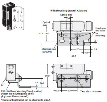
Connector Sensors
E3S-AT66/86 (Receiver)
E3S-AT66/86 (Emitter)
Note: Models numbers for Through-beam Sensors (E3S-AT[]6) are for sets that include both the Emitter and Receiver.
The model number of the Emitter is expressed by adding "-L" to the set model number (example: E3S-AT66-L),
the model number of the Receiver, by adding "-D" (example: E3S-AT66-D). Refer to Ordering Information to
confirm model numbers for Emitter and Receivers.
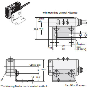
Retro-reflective Sensors (Horizontal)
Pre-wired Sensors
E3S-AR11/21/31/41
Sensors with Connectors
E3S-AR16/36

Retro-reflective Sensors (Vertical)
Pre-wired Sensors
E3S-AR61/71/81/91
Sensors with Connectors
E3S-AR66/86
Diffuse-reflective Sensors (Horizontal)
Pre-wired Sensors
E3S-AD11/12/13/21/22/23/31/32/33/41/42/43
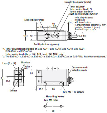
Sensors with Connectors
E3S-AD16/17/18/36/37/38
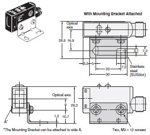
Diffuse-reflective Sensors (Vertical)
Pre-wired Sensors
E3S-AD61/62/63/71/72/73/81/82/83/91/92/93
Sensors with Connectors
E3S-AD66/67/68/86/87/88
Accessories (Order Separately)
Insert-type Long Slit (For Through-beam Model)
E39-S46
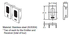
Filters for Mutual Interference Prevention (For Through-beam Model)
E39-E6
Optical Axis Confirmation Reflector (For Through-beam Model)
E39-R5
last update: February 3, 2016
OMRON E3S-A specification
E3S-A Built-in Amplifier Photoelectric Sensor (Medium Size)/Specificationslast update: April 15, 2013
| Sensing method | Through-beam Sensors | Retro-reflective Sensors (with MSR function) | Diffuse-reflective Sensors | |||
|---|---|---|---|---|---|---|
| Model | E3S-AT11, 16, 21, 31, 36, 41, 61, 66, 71, 81, 86, 91 | E3S-AR11, 16, 21, 31, 36, 41, 61, 66, 71, 81, 86, 91 | E3S-AD13, 18, 23, 33, 38, 43, 63, 68, 73, 83, 88, 93 | E3S-AD11, 16, 21, 31, 36, 41, 61, 66, 71, 81, 86, 91 | E3S-AD12, 17, 22, 32, 37, 42, 62, 67, 72, 82, 87, 92 | |
| Sensing distance | 7 m | 2 m (100 mm) *1 (When using E39-R1) | 100 m m ( wide view) (white paper 100 × 100 mm) | 10 to 200 mm (white paper 100 × 100 mm) | 700 mm (white paper 100 × 100 mm) | |
| Standard sensing object | Opaque: 10-mm dia. min. | Opaque: 75-mm dia. min. | --- | |||
| Differential travel | --- | 20% max. of sensing distance | 10% max. of sensing distance | 20% max. of sensing distance | ||
| Directional angle | Both Emitter and Receiver: 3 ° to 15 ° | 3 to 10 ° | --- | |||
| Light source (wavelength) | Red LED (700 nm) | Infrared LED (880 nm) | Red LED (700 nm) | Infrared LED (880 nm) | ||
| Power supply voltage | 10 to 30 VDC, including ripple (p-p) 10% | |||||
| Current consumption | Both Emitter and Receiver: 20 mA max. (plus approx. 15 mA with turbo function) | 30 mA max. (plus approx. 15 mA with turbo function) | 35 mA max. | 30 mA max. (plus approx. 15 mA with turbo function) | 35 mA max. | |
| Control output | Load power supply voltage: 30 VDC max., Load current: 100 mA max. (residual voltage: 1 V max.) Open-collector output (NPN or PNP depending on model), Light-ON/Dark-ON selectable | |||||
| Self-diagnostic output (Only on Sensors with self-diagnostic outputs) | (Only Sensors with self-diagnostic function) Load power supply voltage: 30 VDC max., Load current: 50 mA max. (residual voltage: 1 V max.), Open-collector output (NPN or PNP depending on model) | |||||
| External diagnostic input (Only on Sensors with external diagnostic outputs) | Input voltage | NPN with Emitter OFF: 0 V short-circuit or 1.5 V max. (source current: 1 mA max.) with Emitter ON: Open (leakage current: 0.1 mA max.) PNP with Emitter OFF: + DC short-circuit or - 1.5 VDC max. (sink current: 3 mA max.) with Emitter ON: Open (leakage current: 0.1 mA max.) | --- | |||
| Response time | 0.5 ms max. | |||||
| Protection circuits | Power supply reverse polarity protection, Output short- circuit protection | Power supply reverse polarity protection, Output short-circuit protection, Mutual interference prevention | ||||
| Response time | Operation or reset: 0.5 ms max. | |||||
| Sensitivity adjustment | Two-turn endless adjuster with an indicator | |||||
| Timer function (Only on Sensors with the timer function) | 0 to 100 ms OFF-delay variable adjuster | |||||
| Turbo function (Only on Sensors with the turbo function) | Yes (with turbo switch) | --- | ||||
| Ambient illumination (Receiver side) | Incandescent lamp: 5,000 lx max. Sunlight: 10,000 lx max. | |||||
| Ambient temperature | Operating: - 25°C to 55°C (with no icing or condensation) Storage: - 40°C to 70°C (with no icing or condensation) | |||||
| Ambient humidity | Operating: 35% to 85% (with no condensation) Storage: 35% to 95% (with no condensation) | |||||
| Insulation resistance | 20 MΩ min. at 500 VDC between current-carrying parts and case | |||||
| Dielectric strength | 1,000 VAC, 50/60 Hz for 1 min. between current-carrying parts and case | |||||
| Vibration resistance (destruction) | 10 to 55 Hz, 1.5-mm double amplitude for 2 hours each in X, Y, and Z directions | |||||
| Shock resistance (destruction) | Destruction: 500m/s2, 3 times each in X, Y, and Z directions | |||||
| Degree of protection | IEC IP67; NEMA: 4X (indoors only) *2 | |||||
| Connection method | Pre-wired (standard length: 2 m) or M12 connector | |||||
| Weight (packed state) | Pre-wired cable: Approx. 150 g Connector: Approx. 70 g | Pre-wired cable: Approx. 110 g Connector: Approx. 60 g | Pre-wired cable: Approx. 90 g Connector: Approx. 50 g | |||
| Material | Case | PBT | ||||
| Lens | Denatured polyallylate | |||||
| Mounting Bracket | Stainless steel (SUS304) | |||||
| Accessories | Mounting bracket (with screws), Sensitivity adjustment driver, Sensitivity adjusting knob, Instruction sheet, Close mounting plate (only for Sensors with connectors), and Reflector (only for Retro-reflective Sensors) | |||||
*1. Values in brackets are the minimum required distance between the Sensor and Reflector.
*2. National Electrical Manufacturers Association
last update: April 15, 2013
- NO. E3S-A
- TYPE:Photoelectric Sensors Built-in Amplifier
 Copyright Statement
 - DATE:2021-06-09
- Associated products:
E3S-CL Distance-settable Photoelectric Sensor with Metal Case/Features E3S-LS3[] PCB Sensors/Features