
OMRON E2C-EDASensors/ Proximity Sensors/Separate Amplifier
OMRON E2C-EDA Sensors
- E2C-EDA High Precision Positioning Inductive Proximity Sensor/Specifications
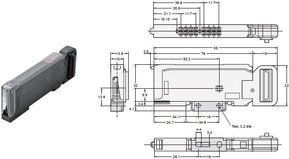
- E2C-EDA High Precision Positioning Inductive Proximity Sensor/Dimensions
- E2C-EDA High Precision Positioning Inductive Proximity Sensor/Catalog
- E2C-EDA High Precision Positioning Inductive Proximity Sensor/Lineup
- Purchase the OMRON E2C-EDA Separate Amplifier
OMRON E2C-EDA Dimensions
/Images/l_1518-25-118690-198x198.jpglast update: March 7, 2013
• Wide variety of Sensor Heads to select according to the application. Flexible cables are used between Preamplifiers and Amplifier Units of the Sensor Heads.
• High resistance to changes in ambient temperature.
Temperature characteristics of 0.08%/°C (for 5.4-dia. models).
• Make simple and reliable detection settings with micron-level precision using the teaching function.
• Check the sensing excess gain level on the digital display.
• Support for high-precision positioning and screening with fine positioning to maximize variations.
• The E2C-EDA0 supports an EtherCAT Sensor Communications Unit or CompoNet Sensor Communications Unit.
last update: March 7, 2013
Purchase the OMRON Separate Amplifier Please fill in the following
If you have just landed here, this product OMRON E2C-EDA Sensors,Sensors is offered online by Tianin FLD Technical Co.,Ltd. This is an online store providing Sensors at wholesale prices for consumers. You can call us or send enquiry, we would give you the prices, packing,deliverty and more detailed information on the E2C-EDA We cooperate with DHL,TNT,FEDEX,UPS,EMS,etc.They guarantee to meet your needs in terms of time and money,even if you need your OMRON E2C-EDASensors tomorrow morning (aka overnight or next day air) on your desk, 2, 3 days or more.Note to international customers, YES, we ship worldwide.
ZJ-FW Fan Ionizer (Area fan type)/Features
CP1W-MODTCP61 CP1 Modbus/TCP Adapter/Features
DCA2 / DCN3 / XS4 DeviceNet Connectors with Thick Cables/Features
Automation Control Environment (ACE) Software/Features
S8TS Switch Mode Power Supply/Features
OMRON E2C-EDA specification
E2C-EDA High Precision Positioning Inductive Proximity Sensor/Specificationslast update: June 01, 2016
Sensor Heads
| Model | E2C- EDR6-F | E2C- ED01(-[]) | E2C- ED02(-[]) | E2C- EM02(-[]) | E2C- EM07(-[]) | E2C- EV05(-[]) | E2C- EM02H | ||
|---|---|---|---|---|---|---|---|---|---|
| 3 dia. × 18 mm | 5.4 dia. × 18 mm | 8 dia. × 22 mm | M10 × 22 mm | M18 × 46.3 mm | 30 × 14 × 4.8 mm | M12 × 22 mm | |||
| Sensing distance | 0.6 mm | 1 mm | 2 mm | 7 mm | 5 mm | 2 mm | |||
| Sensing object | Magnetic metal (The sensing distance will decrease when sensing non-magnetic metal. Refer to Engineering Data (Reference Value) on Catalog.) | ||||||||
| Standard sensing object | 5 × 5 × 3 mm | 10 × 10 × 3 mm | 22 × 22 × 3 mm | 15 × 15 × 3 mm | 20 × 20 × 3 mm | ||||
| Material: iron (S50C) | |||||||||
| Repeat accuracy *1 | 1 μm | 2 μm | 5 μm | 2 μm | |||||
| Hysteresis distance | Variable | ||||||||
| Temper- ature charac- teristic *1 | Sensor Head | 0.3%/°C | 0.08%/°C | 0.04%/°C | 0.2%/°C | ||||
| Preamplifier and Amplifier | 0.08%/°C | ||||||||
| Ambient temper- ature *2 | Operating | -10°C to 60°C (with no icing or condensation) | -10°C to 200°C *3 | ||||||
| Storage | -10°C to 60°C (with no icing or con- densation) | -20°C to 70°C (with no icing or condensation) | |||||||
| Ambient humidity | Operating/storage: 35% to 85% (with no condensation) | ||||||||
| Insulation resistance | 50 MΩ min. (at 500 VDC) | ||||||||
| Dielectric strength | 1,000 VAC at 50/60 Hz for 1 min between current carry parts and case | ||||||||
| Vibration resistance | Destruction: 10 to 55 Hz, 1.5-mm double amplitude for 2 hours each in X, Y, and Z directions | ||||||||
| Shock resistance | Destruction: 500 m/s2 for 3 times each in X, Y, and Z directions | ||||||||
| Degree of protection | IEC60529 IP67 | IEC60529 IP60 *4 | |||||||
| Connection method | Connector (standard cable length: 2.5 m (2 m between Head and Preamplifier) "-F" model cable length: 3.5 m (0.5 m between Head and Preamplifier) | ||||||||
| Weight (packed state) | Approx. 120 g (Models with protective spiral tube ("-S" models) are approx. 90 g heavier.) | ||||||||
| Material | Sensor Head | Case | Brass | Stainless steel | Brass | Zinc | Brass | ||
| Sensing surface | Heat-resistant ABS | PEEK | |||||||
| Clamping nut | --- | Nickel-plated brass | --- | Nickel- plated brass | |||||
| Toothed washer | --- | Zinc-plated iron | --- | Zinc-plated iron | |||||
| Preamplifier | PES | ||||||||
| Accessories | Preamplifier Mounting Brackets, Instruction Manual | ||||||||
*1 The repeat accuracy and temperature characteristic are for a standard sensing object positioned midway through the
rated sensing distance.
*2 A sudden temperature rise even within the rated temperature range may degrade characteristics.
*3 For the Sensor Head only without the preamplifier (−10 to 60°C). With no icing or condensation.
*4 Do not operate in areas exposed to water vapor because the enclosure is not waterproof.
Amplifier Units
| Type | Advanced Models with Twin Outputs | Advanced Models with External Inputs | ||||
|---|---|---|---|---|---|---|
| Pre-wired Model | Model with Wiresaving Connector | Model for Sensor Communications Unit | Pre-wired Model | Model with Wiresaving Connector | ||
| Model | NPN output | E2C-EDA11 | E2C-EDA6 | E2C-EDA0 *1 | E2C-EDA21 | E2C-EDA7 |
| PNP output | E2C-EDA41 | E2C-EDA8 | E2C-EDA51 | E2C-EDA9 | ||
| Supply voltage | 12 to 24 VDC ±10%, ripple (p-p): 10% max. | |||||
| Power consumption | 1,080 mW max. (current consumption: 45 mA at power supply voltage of 24 VDC) | |||||
| Control output | Load power supply voltage: 26.4 VDC max.; NPN/PNP open collector output; load current: 50 mA max. (residual voltage: 1 V max.) | |||||
| Response time | Super-high- speed mode *2 | 150 μs for operation and reset respectively | -- | 150 μs for operation and reset respectively | ||
| High-speed mode | 300 μs for operation and reset respectively | |||||
| Standard mode | 1 ms for operation and reset respectively | |||||
| High- resolution mode | 4 ms for operation and reset respectively | |||||
| Functions | Differential detection | Switchable between single edge and double edge detection mode Single edge: Can be set to 300 μs, 500 μs, 1 ms, 10 ms, or 100 ms Double edge: Can be set to 500 μs, 1 ms, 2 ms, 20 ms, or 200 ms. | ||||
| Timer function | Select from OFF-delay, ON-delay, or one-shot timer. 1 ms to 5 s (1 to 20 ms set in 1-ms increments, 20 to 200 ms set in 10-ms increments, 200 ms to 1 s set in 100-ms increments, and 1 to 5 s set in 1 s-increments) | |||||
| Zero-reset | Negative values can be displayed. Zero-reset is accompanied by a change of detection distance. After zero-reset, some threshold level may also cause a change of the indication by influence of other settings. | |||||
| Initial reset | Settings can be returned to defaults as required. | |||||
| Mutual interference prevention | Possible for up to 5 Units. *2 Intermittent oscillation method (Response time = (number of Units connected + 1) × 15 ms) | |||||
| Hysteresis settings | Setting range: 10 to 2,000 | |||||
| I/O settings | Output setting (Select from channel 2 output, area output, self-diagnosis, or open circuit detection.) | Input setting (Select from teaching, fine positioning, zero- reset, synchronous detection.) | ||||
| Digital display | Select from the following: Incident level + threshold, incident level percentage +threshold, incident light peak level + incident light bottom level (updated with output), long bar display, incident level + peak hold, incident level + channel | |||||
| Display orientation | Switching between normal/reversed display is possible. | |||||
| Ambient temperature *3 | Operating: When connecting 1 to 2 Units: -10°C to 55°C, When connecting 3 to 5 Units: -10°C to 50°C, When connecting 6 to 16 Units: -10°C to 45°C When used in combination with an EDR6-F When connecting 3 to 4 Units: -10°C to 50°C, When connecting 5 to 8 Units: -10°C to 45°C, When connecting 9 to 16 Units: -10°C to 40°C Storage: -20°C to 70°C (with no icing) | |||||
| Ambient humidity | Operating/storage: 35% to 85% (with no condensation) | |||||
| Insulation resistance | 20 MΩ min. (at 500 VDC) | |||||
| Dielectric strength | 1,000 VAC at 50/60 Hz for 1 min | |||||
| Vibration resistance (Destruction) | 10 to 55 Hz with a 1.5-mm double amplitude for 2 hours each in X, Y, and Z directions | 10 to 150 Hz with a 0.7-mm double amplitude for 80 min each in X, Y, and Z directions | 10 to 55 Hz with a 1.5-mm double amplitude for 2 hours each in X, Y, and Z directions | |||
| Shock resistance (Destruction) | 500 m/s2 for 3 times each in X, Y, and Z directions | 150 m/s2 for 3 times each in X, Y, and Z directions | 500 m/s2 for 3 times each in X, Y, and Z directions | |||
| Degree of protection | IEC60529 IP50 | |||||
| Connection method | Pre-wired | Wire-saving connector | Connector for Sensor Communications Unit | Pre-wired | Wire-saving connector | |
| Weight (packed state) | Approx. 100 g | Approx. 55 g | Approx. 55 g | Approx. 100 g | Approx. 55 g | |
| Material | Case | PBT (polybutylene terephthalate) | ||||
| Cover | Polycarbonate | |||||
*1 This model allow you to use an E3X-ECT EtherCAT Sensor Communications Unit or E3X-CRT CompoNet Sensor
Communications Unit.
*2 Communications functions, mutual interference prevention, and communications with the Mobile Console are all disabled
if the detection mode is set to the super-high-speed mode.
*3 The following temperature ranges apply for operation when an E3X-ECT or E3X-CRT Sensor Communications Unit is
used with the E2C-EDA0: Groups of 1 or 2 Amplifier Units: 0 to 55°C, Groups of 3 to 5 Amplifier Units: 0 to 50°C,
Groups of 6 to 16 Amplifier Units: 0 to 45°C, Groups of 17 to 30 Amplifier Units (with the E3X-ECT): 0 to 40°C.
The following temperature ranges apply when an E3X-ECT or E3X-CRT Sensor Communications Unit is used with the
E2C-EDR6-F: Groups of 3 or 4 Amplifier Units: 0 to 50°C, Groups of 5 to 8 Amplifier Units: 0 to 45°C, Groups of 9 to 16
Amplifier Units: 0 to 40°C, Groups of 17 to 30 Amplifier Units (with the E3X-ECT): 0 to 35°C.
last update: June 01, 2016
OMRON E2C-EDA dimension
E2C-EDA High Precision Positioning Inductive Proximity Sensor/Dimensionslast update: July 6, 2018
(Unit: mm)
Tolerance class IT16 applies to dimensions in this data sheet unless otherwise specified.
Sensor Heads
E2C-EDR6-F

E2C-ED01(-F)

E2C-ED02(-F)

E2C-EM02(-F)
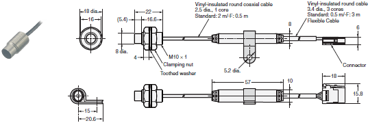
E2C-EM07M(-F)

E2C-EV05(-F)
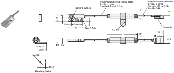
E2C-EM02H

Extension Cables for Sensors Head
E22-XC2R
E22-XC7R

Amplifier Units
Amplifier Units with Cables
E2C-EDA11
E2C-EDA21
E2C-EDA41
E2C-EDA51
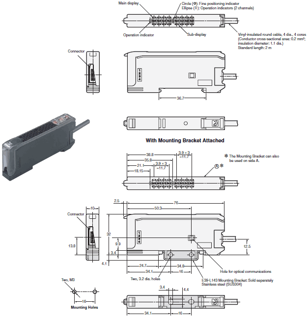
Amplifier Units with Wire-saving Connectors
E2C-EDA6
E2C-EDA7
E2C-EDA8
E2C-EDA9
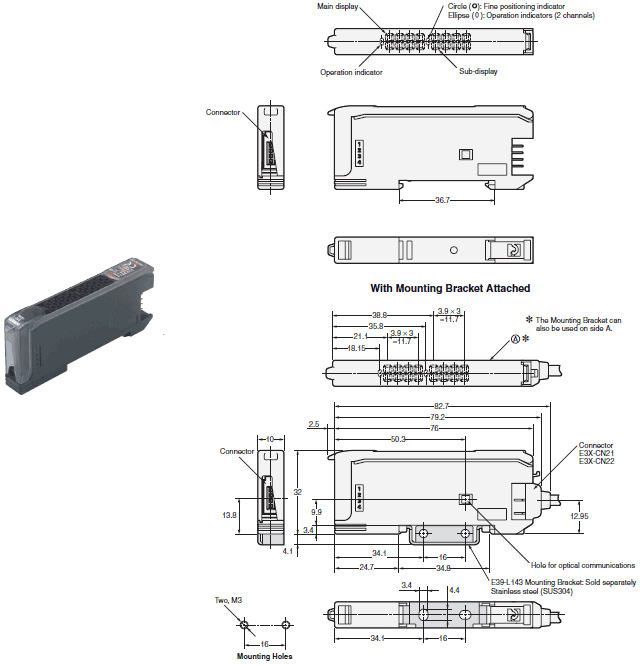
Amplifier Unit with Connector for Sensor Communications Unit
E2C-EDA0
last update: July 6, 2018
OMRON E2C-EDA catalog
E2C-EDA High Precision Positioning Inductive Proximity Sensor/Catalog- Catalog
- Manual
- CAD
English
Global Edition
| Catalog Name | Catalog Number [size] | Last Update | |
|---|---|---|---|
| | - [3413KB] | Jul 06, 201820180706 | E2C-EDA Data Sheet |
OMRON E2C-EDA lineup
E2C-EDA High Precision Positioning Inductive Proximity Sensor/Lineuplast update: April 01, 2015
Sensors
Sensor Heads
| Type | Appearance | Sensing distance | Repeat accuracy | Cable specification | Model | |
|---|---|---|---|---|---|---|
| Shielded | Cylindrical | 3 dia. × 18 mm | 0.6 mm | 1 μm | Free cutting *2 | E2C-EDR6-F |
| 5.4 dia. × 18 mm | 1 mm | 1 μm | Standard *2 | E2C-ED01 | ||
| Free cutting *2 | E2C-ED01-F | |||||
| With Protective Spiral Tube *1 *2 | E2C-ED01-S | |||||
| 8 dia. × 22 mm | 2 mm | 2 μm | Standard *2 | E2C-ED02 | ||
| Free cutting *2 | E2C-ED02-F | |||||
| With Protective Spiral Tube *1 *2 | E2C-ED02-S | |||||
Screw | M10 × 22 mm | 2 mm | 2 μm | Standard *2 | E2C-EM02 | |
| Free cutting *2 | E2C-EM02-F | |||||
| With Protective Spiral Tube *1 *2 | E2C-EM02-S | |||||
Flat | 30 × 14 × 4.8 mm | 5 mm | 2 μm | Standard *2 | E2C-EV05 | |
| Free cutting *2 | E2C-EV05-F | |||||
| With Protective Spiral Tube *1 *2 | E2C-EV05-S | |||||
| Unshielded | Screw | M18 × 46.3 mm | 7 mm | 5 μm | Standard *2 | E2C-EM07M |
| Free cutting *2 | E2C-EM07M-F | |||||
| With Protective Spiral Tube *1 *2 | E2C-EM07M-S | |||||
| Heat- resistant | Screw | M12 × 22 mm | 2 mm | 2 μm | Standard *2 | E2C-EM02H |
*2 Overall length of free-cut cable: 3.5 m, Length from the Sensor Head to the Preamplifier: 0.5 m (Overall length of the
standard cable with Protective Spiral Tube: 2.5 m, Length from the Sensor Head to the Preamplifier: 2 m)
Amplifier Units
Amplifier Units with Cables
| Item | Appearance | Functions | Model | ||
|---|---|---|---|---|---|
| NPN output | PNP output | ||||
| Advanced models | Twin-output models |  | Area output, open circuit detection, differential operation | E2C-EDA11 2M | E2C-EDA41 2M |
| External-input models | Remote setting, differential operation | E2C-EDA21 2M | E2C-EDA51 2M | ||
Amplifier Units with Wire-saving Connectors
(An Amplifier Unit Connector (sold separately) is required.)
| Item | Appearance | Functions | Model | ||
|---|---|---|---|---|---|
| NPN output | PNP output | ||||
| Advanced models | Twin-output models |  | Area output, open circuit detection, differential operation | E2C-EDA6 | E2C-EDA8 |
| External-input models | Remote setting, differential operation | E2C-EDA7 | E2C-EDA9 | ||
E3X-DRT21-S VER.3, use an E3XCN02 Connector without a Cable for the Wire-saving Connector.
Amplifier Unit with Connector for EtherCAT or CompoNet Sensor Communications Units
| Item | Appearance | Functions | Model | Applicable Sensor Communications Unit | |
|---|---|---|---|---|---|
| Advanced model | Twin-output model |  | Area output, open circuit detection, differential operation | E2C-EDA0 | E3X-ECT |
| E3X-CRT | |||||
Wire-saving Connectors (Order Separately)
Note: Protector seals provided.
| Item | Appearance | Cable length | No. of conductors | Model |
|---|---|---|---|---|
| Master Connector |  | 2 m | 4 | E3X-CN21 |
| Slave Connector |  | 2 | E3X-CN22 |
Ordering Precaution for Amplifier Units with Wire-saving Connectors
A Connector is not provided with the Amplifier Unit.
Refer to the following tables when ordering.
| Amplifier Unit | Applicable Connector (Order Separately) | |||
|---|---|---|---|---|
| Model | NPN output | PNP output | Master Connector | Slave Connector |
| Advanced models | E2C-EDA6 | E2C-EDA8 | E3X-CN21 | E3X-CN22 |
| E2C-EDA7 | E2C-EDA9 | |||
When Using 5 Amplifier Units
| Amplifier Units (5 Units) | 1 Master Connector | 4 Slave Connectors |
Mobile Console (Order Separately)
| Appearance | Model | Remarks |
|---|---|---|
 | E3X-MC11-SV2 (model number of set) | Mobile Console with Head, Cable, and AC adapter provided as accessories |
 | E3X-MC11-C1-SV2 | Mobile Console |
 | E3X-MC11-H1 | Head |
 | E39-Z12-1 | Cable (1.5 m) |
E3X-MC11-S, some functions may not operate. For details, refer to Ratings and Specifications for E3X-DA-S/MDA.
Accessories (Order Separately)
Mounting Bracket
A Mounting Bracket is not provided with the Amplifier Unit. Order a Mounting Bracket separately if required.
| Appearance | Model | Quantity |
|---|---|---|
 | E39-L143 | 1 |
End Plate
An End Plate is not provided with the Amplifier Unit. Order an End Plate separately if required.
| Appearance | Model | Quantity |
|---|---|---|
 | PFP-M | 1 |
Extension Cables for Sensor Head
An Extension Cable is not provided with the Amplifier Unit. Order an Extension Cable separately if required.
| Cable length | Model | Quantity |
|---|---|---|
| 2 m | E22-XC2R | 1 |
| 7 m | E22-XC7R |
last update: April 01, 2015
- NO. E2C-EDA
- TYPE:Proximity Sensors Separate Amplifier
 Copyright Statement
 - DATE:2021-06-13
- Associated products:
E2EC Cable Amplifier Proximity Sensor/Features E2C / E2C-H Separate Amplifier Proximity Sensor with Adjustment Potentiometer/Features