OMRON S8TSPower Supplies / In Addition/ Power Supplies/Switch mode power supplies
OMRON S8TS Power Supplies / In Addition
OMRON S8TS Dimensions
/Images/l_805-25-119018-198x198.jpglast update: April 21, 2017
• One model covers 30 to 120 W (12-V models).
• One model covers 60 to 240 W (24-V models).
• Easy creation of multi-power supply configurations with different output power supplies connected together (5-V, 12-V, and 24-V models).
• Improve power supply system reliability by creating N+1 redundant systems (12-V and 24-V models).
• RoHS-compliant
• Input conditions: 80 to 370 VDC supported for DC input too (EC Directives and safety standards are not applicable.)
• Operating temperatures to –20°C (24-V models).
last update: April 21, 2017
Purchase the OMRON Switch mode power supplies Please fill in the following
If you have just landed here, this product OMRON S8TS Power Supplies / In Addition,Power Supplies / In Addition is offered online by Tianin FLD Technical Co.,Ltd. This is an online store providing Power Supplies / In Addition at wholesale prices for consumers. You can call us or send enquiry, we would give you the prices, packing,deliverty and more detailed information on the S8TS We cooperate with DHL,TNT,FEDEX,UPS,EMS,etc.They guarantee to meet your needs in terms of time and money,even if you need your OMRON S8TSPower Supplies / In Addition tomorrow morning (aka overnight or next day air) on your desk, 2, 3 days or more.Note to international customers, YES, we ship worldwide.
NY51[]-A Industrial PC Platform NY-series IPC Programmable Multi-Axis Controller/Features
3Z4S-LT Series Lighting System/Features
H3RN-[]-B Solid-state timer/Features
H3CA Solid-state Timer/Features
CK3W-PD048 CK3W Power Supply Unit/Features
OMRON S8TS lineup
S8TS Switch Mode Power Supply/Lineuplast update: September 24, 2012
Note: For details on normal stock models, contact your nearest OMRON representative.
Basic Block
| Output voltage | Output current | Screw terminal Model | Connector terminal Model *3 | ||
|---|---|---|---|---|---|
| With Bus Line Connectors *1 | Without Bus Line Connectors *2 | With Bus Line Connectors *1 | Without Bus Line Connectors *2 | ||
| 5 V | 5 A | --- | S8TS-02505 | --- | S8TS-02505F |
| 12 V | 2.5 A | S8TS-03012-E1 | S8TS-03012 | S8TS-03012F-E1 | S8TS-03012F |
| 24 V | 2.5 A | S8TS-06024-E1 | S8TS-06024 | S8TS-06024F-E1 | S8TS-06024F |
Bus Line Connector
| Specifications | Number of Connectors | Model number |
|---|---|---|
| Connector with DC line connected (For parallel operation) | 1 Connector | S8T-BUS01 |
| 10 Connectors *4 | S8T-BUS11 | |
| Connector with DC line not connected (Not for parallel operation) | 1 Connector | S8T-BUS02 |
| 10 Connectors *5 | S8T-BUS12 |
*1. One S8T-BUS01 Connector and one S8T-BUS02 Connector are included as accessories.
*2. Bus Line Connectors are ordered separately. When connecting Power Supplies with Bus Line Connectors, order the
Bus Line Connectors separately.
*3. Attached connectors: 2ESDPLM-05P (for output terminal) and 3ESDPLM-03P (for input terminal) made by DINKLE
ENTERPRISE.
*4. One package contains 10 S8T-BUS01 Connectors.
*5. One package contains 10 S8T-BUS02 Connectors.
last update: September 24, 2012
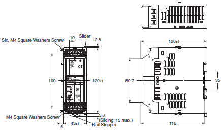
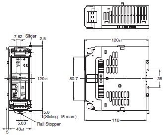
OMRON S8TS dimension
S8TS Switch Mode Power Supply/Dimensionslast update: July 01, 2016
S8TS-[][][][][]

S8TS-[][][][][]F

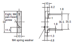
DIN Rails (Order Separately)
Mounting Rails (Material: Aluminum)
PFP-100N
PFP-50N

PFP-100N2

End Plate
PFP-M

last update: July 01, 2016
OMRON S8TS specification
S8TS Switch Mode Power Supply/Specificationslast update: September 24, 2012
12/24-V Models (Basic Block: S8TS-06024[]/S8TS-03012[])
| Item | Single operation | Parallel operation | ||
|---|---|---|---|---|
| Efficiency (TYP.) | 24-V models: 80% TYP. ; 12-V models: 73% TYP. (with rated input, 100% load) | |||
| Input | Voltage *1 | Ratings: 100 to 240 VAC (Allowable range: 85 to 264 VAC, 80 to 370 VDC *8) | ||
| Frequency *1 | 50/60 Hz (47 to 63 Hz) | |||
| Current | 100 V input | 24-V models: 1.0 A max. 12-V models: 0.7 A max. | 24-V models: 1.0 A × (No. of Blocks) max. 12-V models: 0.7 A × (No. of Blocks) max. | |
| 200 V input | 24-V models: 0.5 A max. 12-V models: 0.4 A max. | 24-V models: 0.5 A × (No. of Blocks) max. 12-V models: 0.4 A × (No. of Blocks) max. | ||
| Power factor | 24-V models: 0.9 min.; 12-V models: 0.8 min. (with rated input, 100% load) | |||
| Harmonic current emissions | Conforms to EN61000-3-2 | |||
| Leakage current | 100 V input | 0.35 mA max. | 0.35 mA × (No. of Blocks) max. | |
| 240 V input | 0.7 mA max. | 0.7 mA × (No. of Blocks) max. | ||
| Inrush current *5 | 100 V input | 17.5 A max. (for a cold start at 25°C) | 17.5 A × (No. of Blocks) max. (for a cold start at 25°C) | |
| 200 V input | 35 A max. (for a cold start at 25°C) | 35 A × (No. of Blocks) max. (for a cold start at 25°C) | ||
| Output *4 | Voltage adjustment range | 24-V models: 22 to 28 V 12-V models: 12 V ±10% (with V.ADJ) *2 | ||
| Ripple | 2% (p-p) max. | |||
| Input variation influence | 0.5% max. (with 85 to 264 VAC input, 100% load) | |||
| Load variation influence | 2% max. (with rated input, 10% to 100% load) | 3% max. (with rated input, 10% to 100% load) | ||
| Temperature variation influence | 0.05%/°C max. (with rated input and output) | |||
| Startup time | 1,000 ms max. (with 100/200 VAC, rated input) | |||
| Hold time *5 | 20 ms min. (with 100/200 VAC, rated input) | |||
| Addi- tional func- tions | Overload protection *5 | 105% to 140% of rated load current, voltage drop, automatic reset | 100% to 140% of rated load current, voltage drop, automatic reset | |
| Overvoltage protection *5 *6 | Yes | |||
| Parallel operation | Yes (Up to 4 Blocks) | |||
| N+1 redundant system | Yes (Up to 5 Blocks) | |||
| Series operation | Yes | |||
| Undervoltage indicator *5 | Yes (color: red) | |||
| Undervoltage detection output *5 | Yes (open collector output), 30 VDC max., 50 mA max. | |||
| Other | Ambient operating temperature *5 | Refer to the derating curve in Engineering Data on Data Sheet (with no icing or condensation). | ||
| Storage temperature | -25 to 65°C | |||
| Ambient operating humidity | 25% to 85% (Storage humidity: 25% to 90%) | |||
| Dielectric strength | 3.0 kVAC for 1 minute (between all inputs and all outputs; detection current: 20 mA) | |||
| 2.0 kVAC for 1 minute (between all inputs and PE terminal; detection current: 20 mA) | ||||
| 1.0 kVAC for 1 minute (between all outputs and PE terminal; detection current: 20 mA) | ||||
| Insulation resistance | 100 MΩ min. (between all outputs, and all inputs/PE terminal) at 500 VDC | |||
| Vibration resistance *7 | 10 to 55 Hz, 0.375-mm single amplitude for 2 h each in X, Y, and Z directions | |||
| Shock resistance *7 | 150 m/s2, 3 times each in ±X, ±Y, and ±Z directions | |||
| Output indicator | Yes (color: green) | |||
| EMI *8 | Conducted Emission | Conforms to EN61204-3 EN55011 Class B and based on FCC Class A *9 | ||
| Radiated Emission | Conforms to EN61204-3 EN55011 Class B *9 | |||
| EMS *8 | Conforms to EN61204-3 High severity levels *9 | |||
| Approved standards *8 | 24 V model UL Listed: UL508 (Listing, Class2 Output: Per UL1310) *3 UL UR: UL60950-1 (Recognition) cUL Listed: CSA C22.2 No.107.1 (Class2 Output: Per CSA C22.2 No.223) *3 cUR: CSA C22.2 No.60950-1 EN/VDE: EN50178 (=VDE0160) , EN60950-1 (=VDE0805 Teil1) 12 V model UL Listed: UL508 (Listing) UL UR: UL60950-1 (Recognition) cUL Listed: CSA C22.2 No.107.1 cUR: CSA C22.2 No.60950-1 EN/VDE: EN50178 (=VDE0160) , EN60950-1 (=VDE0805 Teil1) | |||
| Weight | 450 g max. | 450 g × (No. of Blocks) max. | ||
*1. Do not use an inverter output for the Power Supply. Inverters with an output frequency of 50/60 Hz are available, but
the rise in the internal temperature of the Power Supply may result in ignition or burning.
*2. Refer to Data sheet for details on adjusting the output voltage for parallel operation. If set to less than −10%, the
undervoltage detection function may operate. Ensure that the output capacity and output current after adjustment do
not exceed the rated output capacity and rated output current respectively. Adjusting V.ADV may cause the output
voltage to exceed the voltage range. When adjusting the output voltage, confirm the actual output voltage from the
Power Supply and be sure that the load is not damaged.
*3. Class 2 approval does not apply to parallel operation.
*4. The output current is specified at power output terminals.
*5. Refer to the Engineering Data on Data sheet for details.
*6. To reset the protection, turn OFF the input power for one minute or longer and then turn it back again.
*7. Be sure to mount End Plates (PFP-M) on both ends of the Power Supply.
*8. The range for compliance with EC Directives and safety standards (UL, EN, etc.) is 100 to 240 VAC (85 to 264 VAC).
*9. The noise level depends on the wiring method and other factors. Insert one clamp filter (the ZCAT2436-1330A from
TDK) as a noise countermeasure on the input line and ground line combined.
5-V Models (Basic Block: S8TS-02505[])
| Item | Single operation | ||
|---|---|---|---|
| Efficiency (typical) | 73% TYP. (with rated input, 100% load) | ||
| Input | Voltage *1 | Ratings: 100 to 240 VAC (Allowable range: 85 to 264 VAC, 80 to 370 VDC *7) | |
| Frequency *1 | 50/60 Hz (47 to 63 Hz) | ||
| Current | 100 V input | 0.7 A max. | |
| 200 V input | 0.4 A max. | ||
| Power factor | 0.8 min. (with rated input, 100% load) | ||
| Harmonic current emissions | Conforms to EN61000-3-2 | ||
| Leakage current | 100 V input | 0.35 mA max. | |
| 240 V input | 0.7 mA max. | ||
| Inrush current *5 | 100 V input | 17.5 A max. (for a cold start at 25°C) | |
| 200 V input | 35 A max. (for a cold start at 25°C) | ||
| Output *3 | Voltage adjustment range | 5 V ± 10% (with V. ADJ) *2 | |
| Ripple | 2% (p-p) max. | ||
| Input variation influence | 0.5% max. (with 85 to 264 VAC input, 100% load) | ||
| Temperature variation influence | 0.05%/°C max. (with rated input and output) | ||
| Load variation influence | 1.5% max. (with rated input, 10% to 100% load) | ||
| Startup time *4 | 1,000 ms max. (with 100/200 VAC, rated input) | ||
| Hold time *4 | 20 ms min. (with 100/200 VAC, rated input) | ||
| Addi- tional func- tions | Overload protection *4 | 105% to 140% of rated load current, voltage drop, automatic reset | |
| Overvoltage protection *4 *5 | Yes | ||
| Parallel operation | No | ||
| N+1 redundant system | No | ||
| Series operation | Yes (with the external diode) | ||
| Undervoltage indicator *4 | Yes (color: red) | ||
| Undervoltage detection output *4 | Yes (open collector output), 30 VDC max., 50 mA max. | ||
| Other | Ambient operating temperature *4 | Refer to the derating curve in Engineering Data on Data Sheet. | |
| Storage temperature | -25 to 65°C (with no icing or condensation) | ||
| Ambient operating humidity | 25% to 85%, Storage: 25% to 90% | ||
| Dielectric strength | 3.0 kVAC, 50/60 Hz for 1 minute (between all inputs and all outputs; detection current: 20 mA) | ||
| 2.0 kVAC, 50/60 Hz for 1 minute (between all inputs and PE terminal; detection current: 20 mA) | |||
| 1.0 kVAC for 1 minute (between all outputs and PE terminal; detection current: 20 mA) | |||
| Insulation resistance | 100 MΩ min. (between all outputs and inputs/PE terminal) at 500 VDC | ||
| Vibration resistance *6 | 10 to 55 Hz, 0.375-mm single amplitude for 2 h each in X, Y, and Z directions | ||
| Shock resistance *6 | 150 m/s2, 3 times each in ±X, ±Y, and ±Z directions | ||
| Output indicator | Yes (color: green) | ||
| EMI *7 | Conducted Emission | Conforms to EN61204-3 EN55011 Class B and based on FCC Class A | |
| Radiated Emission | Conforms to EN61204-3 EN55011 Class B | ||
| EMS *7 | Conforms to EN61204-3 High severity levels | ||
| Approved standards *7 | UL Listed: UL508 (Listing) UL UR: UL60950-1 (Recognition) cUL Listed: CSA C22.2 No.107.1 cUR: CSA C22.2 No.60950-1 EN/VDE: EN50178 (=VDE0160), EN60950-1 (=VDE0805 Teil1) | ||
| Weight | 450 g max. | ||
*1. Do not use an inverter output for the Power Supply. Inverters with an output frequency of 50/60 Hz are available, but
the rise in the internal temperature of the Power Supply may result in ignition or burning.
*2. If set to less than −10%, the undervoltage detection function may operate. Ensure that the output capacity and output
current after adjustment do not exceed the rated output capacity and rated output current respectively. If the output
voltage adjuster (V. ADJ) is turned, the voltage will increase by more than 10% of the output voltage, confirm the actual
output voltage from the Power Supply and be sure that the load is not damaged.
*3. The output current is specified at power output terminals.
*4. Refer to the Engineering Data on Data sheet for details.
*5. To reset the protection, turn OFF the input power for one minute or longer and then turn it back again.
*6. Be sure to mount End Plates (PFP-M) on both ends of the Power Supply.
*7. The range for compliance with EC Directives and safety standards (UL, EN, etc.) is 100 to 240 VAC (85 to 264 VAC).
last update: September 24, 2012
OMRON S8TS catalog
S8TS Switch Mode Power Supply/Catalog- Catalog
- Manual
- CAD
English
Global Edition
| Catalog Name | Catalog Number [size] | Last Update | |
|---|---|---|---|
| | - [1977KB] | Jul 01, 201620160701 | S8TS Data Sheet |
- NO. S8TS
- TYPE:Power Supplies Switch mode power supplies
 Copyright Statement
 - DATE:2021-06-15
- Associated products:
S8AS Smart Power Supply/Features S82S Switch Mode Power Supply (3/7.5-W Models)/Features