OMRON CJ1W-PA / PDAutomation Systems/ Programmable Controllers/CJ1
OMRON CJ1W-PA / PD Automation Systems
OMRON CJ1W-PA / PD Dimensions
/Images/l_1639-25-118583-198x198.jpglast update: September 24, 2012
Please refer to the overview page for features of this product.
• The replacement notification function can prevent an overflow of the system due to the power lifetime. (CJ1W-PA205C only)
• Power Supply Unit provides wide variations according to the system scale up to maximum 25 W.
• Power Supply Unit provides wide variations according to the power supply (100 to 240 V AC/ 24 V DC) status.
• The output contact during operation enables you to check the CPU operation. (CJ1W-PA205R only)
• Conforming to the SEMI-F47 Standard. *
* AC input type, 200 V min. input.
last update: September 24, 2012
Purchase the OMRON CJ1 Please fill in the following
If you have just landed here, this product OMRON CJ1W-PA / PD Automation Systems,Automation Systems is offered online by Tianin FLD Technical Co.,Ltd. This is an online store providing Automation Systems at wholesale prices for consumers. You can call us or send enquiry, we would give you the prices, packing,deliverty and more detailed information on the CJ1W-PA / PD We cooperate with DHL,TNT,FEDEX,UPS,EMS,etc.They guarantee to meet your needs in terms of time and money,even if you need your OMRON CJ1W-PA / PDAutomation Systems tomorrow morning (aka overnight or next day air) on your desk, 2, 3 days or more.Note to international customers, YES, we ship worldwide.
E3ZS, E3FS Single-beam Safety Sensor/Features
E4PA-N Ultrasonic Displacement Sensor/Features
3Z4S-LE VS-MC Series (φ16 Straight lens-barrel Type) Non-telecentric Macro Lens for C-mount Came...
G3NE Solid State Relays/Features
K3HB-C Up/Down Counting Pulse Indicator/Features
OMRON CJ1W-PA / PD lineup
CJ1W-PA / PD CJ-series Power Supply Unit/Lineuplast update: September 24, 2012
International Standards
- The standards are abbreviated as follows: U: UL, U1: UL(Class I Division 2 Products for Hazardous Locations), C: CSA, UC: cULus, UC1: cULus (Class I Division 2 Products for Hazardous Locations), CU: cUL, N: NK, L: Lloyd, and CE: EC Directives.
- Contact your OMRON representative for further details and applicable conditions for these standards.
Power Supply Units
| Product name | Power supply voltage | Output capacity | Options | Model | Stand- ards | |||||
|---|---|---|---|---|---|---|---|---|---|---|
| 5-VDC output capacity | 24-VDC output capacity | Total power con- sumption | 24-VDC service power supply | RUN output | Mainte- nance forecast monitor | |||||
| AC Power Supply Unit |  | 100 to 240 VAC | 5 A | 0.8 A | 25 W | No | No | Yes | CJ1W-PA205C | UC1, N, L, CE |
 | Yes | No | CJ1W-PA205R | |||||||
 | 2.8 A | 0.4 A | 14 W | No | No | CJ1W-PA202 | ||||
| DC Power Supply Unit |  | 24 VDC | 5 A | 0.8 A | 25 W | No | No | CJ1W-PD025 | ||
 | 2 A | 0.4 A | 19.6 W | No | No | CJ1W-PD022 | UC1, CE | |||
Note: This unit cannot be used with the Machine Automation Controller NJ-series.
Accessories
There is no accessory for the CJ series Power Supply Unit.
last update: September 24, 2012
OMRON CJ1W-PA / PD catalog
CJ1W-PA / PD CJ-series Power Supply Unit/Catalog- Catalog
- Manual
- CAD
English
Global Edition
| Catalog Name | Catalog Number [size] | Last Update | |
|---|---|---|---|
| | - [1074KB] | Mar 28, 201220120328 | CJ1W-PA/PD Data Sheet |
OMRON CJ1W-PA / PD dimension
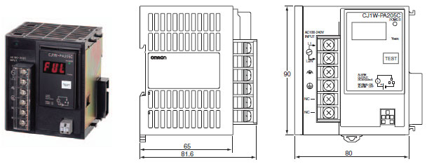
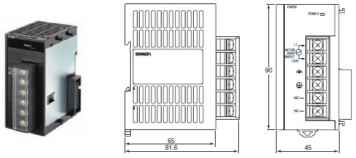
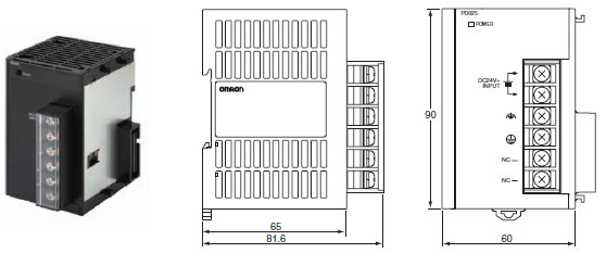
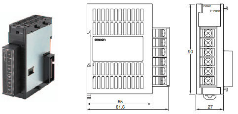
CJ1W-PA / PD CJ-series Power Supply Unit/Dimensionslast update: September 24, 2012
CJ1W-PA205R

CJ1W-PA205C
CJ1W-PA202
CJ1W-PD025
CJ1W-PD022
last update: September 24, 2012
OMRON CJ1W-PA / PD specification
CJ1W-PA / PD CJ-series Power Supply Unit/Specificationslast update: September 24, 2012
| Item | Specifications | ||
|---|---|---|---|
| Model | CJ1W-PA205R | CJ1W-PA205C | CJ1W-PA202 |
| Supply voltage | 100 to 240 V AC (wide-range), 50/60 Hz | ||
| Operating voltage and frequency ranges | 85 to 264 V AC, 47 to 63 Hz | ||
| Power consumption | 100 VA max. | 50 VA max. | |
| Inrush current *1 | At 100 to 120 V AC: 15 A/8 ms max. for cold start at room temperature At 200 to 240 V AC: 30 A/8 ms max. for cold start at room temperature | At 100 to 120 V AC: 20 A/8 ms max. for cold start at room temperature At 200 to 240 V AC: 40 A/8 ms max. for cold start at room temperature | |
| Output capacity *7 | 5.0 A, 5 V DC (including supply to CPU Unit) | 2.8 A, 5 V DC (including supply to CPU Unit) | |
| 0.8 A, 24 V DC | 0.4 A, 24 V DC | ||
| Total: 25 W max. | Total: 14 W max. | ||
| Output terminal (service supply) | Not provided. | ||
| RUN output *2 | Contact configuration: SPST-NO Switch capacity: 250 V AC, 2 A (resistive load) 120 V AC, 0.5 A (inductive load), 24 V DC, 2A (resistive load) 24 V DC, 2 A (inductive load) | Not provided. | |
| Replacement notification function | Not provided. | With Alarm output (open-collector output) 30 V DC max., 50 mA max. | Not provided. |
| Insulation resistance | 20 MΩ min. (at 500 V DC) between AC external and GR terminals *3 | 20 MΩ min. (at 500 V DC) between all external terminals and GR terminal *3, and between all alarm output terminals. 20 MΩ 1 min. (at 250 V DC) between all alarm output terminals and GR terminal *3. | 20 MΩ min. (at 500 V DC) between AC external and GR terminals *3 |
| Dielectric strength *4 | 2,300 V AC 50/60 Hz for 1 min between AC external and GR terminals *3 Leakage current: 10 mA max. | 2,300 VAC, 50/60 Hz for 1 min between all external terminals and GR terminal *3 and between all alarm output terminals with a leakage current of 10 mA max. 1,000 V AC, 50/60 Hz for 1 min between all alarm output terminals and GR terminal *3 with a leakage current of 10 mA max. | 2,300 V AC 50/60 Hz for 1 min between AC external and GR terminals *3 Leakage current: 10 mA max. |
| 1,000 V AC, 50/60 Hz for 1 minute between DC external and GR terminals *3 Leakage current: 10 mA max. | |||
| Noise immunity | 2 kV on power supply line (conforming to IEC61000-4-4) | ||
| Vibration resistance | Conforms to IEC60068-2-6 5 to 8.4 Hz with 3.5-mm amplitude, 8.4 to 150 Hz Acceleration of 9.8 m/s2 for 100 min in X, Y, and Z directions (10 sweeps of 10 min each = 100 min) | ||
| Shock resistance | Conforms to IEC60068-2-27 147 m/s2, 3 times in X, Y, and Z directions (100 m/s2 for Relay Output Units) | ||
| Ambient operating temperature | 0 to 55 ° C | ||
| Ambient operating humidity | 10% to 90% (with no condensation) | 10% to 90% (with no condensation) *5 | 10% to 90% (with no condensation) |
| Atmosphere | Must be free from corrosive gases. | ||
| Ambient storage temperature | - 20 to 70 ° C (excluding battery) | - 20 to 75 ° C *5 | - 20 to 75 ° C (excluding battery) |
| Grounding | Less than 100 Ω | ||
| Enclosure | Mounted in a panel. | ||
| Weight | All models are each 5 kg max. | ||
| CPU Rack dimensions | 90.7 to 466.7 × 90 × 65 mm (W × H × D) (not including cables) Note: W = a + b + 20 × n + 31 × m + 14.7 a: Power Supply Unit: PA205R and PA205C = 80; PA202 = 45; PD025 = 60; PD022=27 b: CPU Unit: CJ1-H or CJ1 = 62; CJ1M-CPU1[] = 31; CJ1M-CPU2[] = 49 The total width is given by the following: W = 156.7 + n × 20 + m × 31, where n is the number of 32-point I/O Units or I/O Control Units and m is the number of other Units. | ||
| Safety measures | Conforms to cULus and EC Directives. | ||
| Item Power Supply Unit | Specifications | |
|---|---|---|
| CJ1W-PD025 | CJ1W-PD022 | |
| Supply voltage | 24 VDC | |
| Operating voltage and frequency ranges | 19.2 to 28.8 V DC | 21.6 to 26.4 V DC |
| Power consumption | 50 W max. | 35 W max. |
| Inrush current *1 | At 24 V DC: 30 A/20 ms max. for cold start | |
| Output capacity *7 | 5.0 A, 5 V DC (including supply to CPU Unit) | 2.0 A, 5 V DC (including supply to CPU Unit) |
| 0.8 A, 24 V DC | 0.4 A, 24 V DC | |
| Total: 25 W max. | Total: 19.6 W max. | |
| Output terminal (service supply) | Not provided. | |
| RUN output *2 | Not provided. | |
| Replacement notification function | Not provided. | |
| Insulation resistance | 20 MΩ min. (at 500 V DC) between DC external and GR terminals *3 | --- *6 |
| Dielectric strength *4 | 1,000 V AC, 50/60 Hz for 1 min between DC external and GR terminals *3 Leakage current: 10 mA max. | --- *6 |
| Noise immunity | 2 kV on power supply line (conforming to IEC61000-4-4) | |
| Vibration resistance | Conforms to IEC60068-2-6 5 to 8.4 Hz with 3.5-mm amplitude, 8.4 to 150 Hz Acceleration of 9.8 m/s2 for 100 min in X, Y, and Z directions (10 sweeps of 10 min each = 100 min) | |
| Shock resistance | Conforms to IEC60068-2-27 147 m/s2, 3 times in X, Y, and Z directions (100 m/s2 for Relay Output Units) | |
| Ambient operating temperature | 0 to 55 ° C | |
| Ambient operating humidity | 10% to 90% (with no condensation) | |
| Atmosphere | Must be free from corrosive gases. | |
| Ambient storage temperature | - 20 to 75 ° C (excluding battery) | |
| Grounding | Less than 100 Ω | |
| Enclosure | Mounted in a panel. | |
| Weight | All models are each 5 kg max. | |
| CPU Rack dimensions | 90.7 to 466.7 × 90 × 65 mm (W × H × D) (not including cables) Note: W = a + b + 20 × n + 31 × m + 14.7 a: Power Supply Unit: PA205R and PA205C = 80; PA202 = 45; PD025 = 60; PD022=27 b: CPU Unit: CJ1-H or CJ1 = 62; CJ1M-CPU1[] = 31; CJ1M-CPU2[] = 49 The total width is given by the following: W = 156.7 + n × 20 + m × 31, where n is the number of 32-point I/O Units or I/O Control Units and m is the number of other Units. | |
| Safety measures | Conforms to cULus and EC Directives. | |
*1. Disconnect the Power Supply Units LG terminal from the GR terminal when testing insulation and dielectric strength.
Testing the insulation and dielectric strength with the LG terminal and the GR terminals connected will damage
internal circuits in the CPU Unit.
*2. Supported only when mounted to CPU Rack.
*3. The inrush current is given for a cold start at room temperature. The inrush control circuit uses a thermistor element
with a low-temperature current control characteristic. If the ambient temperature is high or the PLC is hot-started, the
thermistor will not be sufficiently cool, and the inrush currents given in the table may be exceeded by up to twice the
given values. When selecting fuses or breakers for external circuits, allow sufficient margin in shut-off performance.
*4. Maintain an ambient storage temperature of −25 to 30°C and relative humidity of 25% to 70% when storing the Unit for
longer than 3 months to keep the replacement notification function in optimum working condition.
*5. Change the applied voltage gradually using the adjuster on the Tester. If the full dielectric strength voltage is applied
or turned OFF using the switch on the Tester, the generated impulse voltage may damage the Power Supply Unit.
*6. CJ1W-PD022 is not insulated between the primary DC power and secondary DC power.
*7. Internal components in the Power Supply Unit will deteriorate or be damaged if the Power Supply Unit is used for an
extended period of time exceeding the power supply output capacity or if the outputs are shorted.
Checking Current Consumption and Power Consumption
After selecting a Power Supply Unit based on considerations such as the power supply voltage, calculate the current and power requirements for each Rack.
Condition 1: Current Requirements
There are two voltage groups for internal power consumption: 5 V and 24 V.
Current consumption at 5 V (internal logic power supply)
Current consumption at 24 V (relay driving power supply)
Condition 2: Power Requirements
For each Rack, the upper limits are determined for the current and power that can be provided to the mounted Units. Design the system so that the total current consumption for all the mounted Units does not exceed the maximum total power or the maximum current supplied for the voltage groups shown in the following tables.
The maximum current and total power supplied for CPU Racks and Expansion Racks according to the Power Supply Unit model are shown below.
Note: 1. For CPU Racks, include the CPU Unit current and power consumption in the calculations. When expanding, also
include the current and power consumption of the I/O Control Unit in the calculations.
2. For Expansion Racks, include the I/O Interface Unit current and power consumption in the calculations.
| Power Supply Units | Max. current supplied | Max. total power supplied | |
|---|---|---|---|
| 5 V | 24 V (relay driving current) | ||
| CJ1W-PA205R | 5.0 A | 0.8 A | 25 W |
| CJ1W-PA205C | 5.0 A | 0.8 A | 25 W |
| CJ1W-PA202 | 2.8 A | 0.4 A | 14 W |
| CJ1W-PD025 | 5.0 A | 0.8 A | 25 W |
| CJ1W-PD022 | 2.0 A | 0.4 A | 19.6 W |
Conditions 1 and 2 below must be satisfied.
Condition 1: Maximum Current
(1) Total Unit current consumption at 5 V ≤ (A) value
(2) Total Unit current consumption at 24 V ≤ (B) value
Condition 2: Maximum Power
(1) × 5 V + (2) × 24 V ≤ (C) value
Example: Calculating Total Current and Power Consumption
Example: When the Following Units are Mounted to a CJ-series CPU Rack Using a CJ1W-PA202 Power Supply Unit
| Unit type | Model | Quantity | Voltage group | |
|---|---|---|---|---|
| 5 V | 24 V | |||
| CPU Unit | CJ1G-CPU45H | 1 | 0.910 A | --- |
| I/O Control Unit | CJ1W-IC101 | 1 | 0.020 A | --- |
| Basic I/O Units (Input Units) | CJ1W-ID211 | 2 | 0.080 A | --- |
| CJ1W-ID231 | 2 | 0.090 A | --- | |
| Basic I/O Units (Output Units) | CJ1W-OC201 | 2 | 0.090 A | 0.048 A |
| Special I/O Unit | CJ1W-DA041 | 1 | 0.120 A | --- |
| CPU Bus Unit | CJ1W-CLK23 | 1 | 0.350 A | --- |
| Current consumption | Total | 0.910 + 0.020 + 0.080 × 2 + 0.090 × 2 + 0.090 × 2 + 0.120 + 0.350 | 0.048 A × 2 | |
| Result | 1.92 A ( ≤ 2.8 A) | 0.096 A ( ≤ 0.4 A) | ||
| Power consumption | Total | 1.92 × 5 V = 9.60 W | 0.096 A × 24 V = 2.304 W | |
| Result | 9.60 + 2.304 = 11.904 W ( ≤ 14 W) | |||
last update: September 24, 2012
- NO. CJ1W-PA / PD
- TYPE:Programmable Controllers CJ1 Power Supply Units
- DATE:2021-06-11
- Associated products:
CJ1M-CPU2[] CJ-series CJ1M CPU Units (with Built-in I/O)/Features CJ1W-SRM21 CJ-series CompoBus/S Master Unit/Features