
OMRON E3ZS, E3FSSafety Components/ Safety Sensors/ Copyright Statement
OMRON E3ZS, E3FS Safety Components
OMRON E3ZS, E3FS Dimensions
/Images/l_1519-25-118755-198x198.jpglast update: April 21, 2016
Connect to a G9SP to Create a Type 2 Safety Sensor

last update: April 21, 2016
Purchase the OMRON  Copyright Statement Please fill in the following
If you have just landed here, this product OMRON E3ZS, E3FS Safety Components,Safety Components is offered online by Tianin FLD Technical Co.,Ltd. This is an online store providing Safety Components at wholesale prices for consumers. You can call us or send enquiry, we would give you the prices, packing,deliverty and more detailed information on the E3ZS, E3FS We cooperate with DHL,TNT,FEDEX,UPS,EMS,etc.They guarantee to meet your needs in terms of time and money,even if you need your OMRON E3ZS, E3FSSafety Components tomorrow morning (aka overnight or next day air) on your desk, 2, 3 days or more.Note to international customers, YES, we ship worldwide.
TM Series Collaborative Robots/Features
EE-SX47 / SX67 Slot-type Photomicrosensor with connector or pre-wired models (Non-modulated)*1/Fe...
K7L-AT50[] / AT50D[][] Liquid Leakage Sensor Amplifier/Liquid Leakage Sensor Amplifier with Disco...
G9H Hybrid Power Relay/Features
Hornet 565 Parallel Robots/Features
OMRON E3ZS, E3FS specification
E3ZS, E3FS Single-beam Safety Sensor/Specificationslast update: December 09, 2015
E3ZS/E3FS
| Model | E3ZS-T81A | E3FS-10B4 2M | E3FS-10B4-M1-M | |
|---|---|---|---|---|
| Sensor type | Through-beam models | |||
| Safety category | See Applicable standards. | |||
| Standard sensing object | Opaque object: 18 mm in diameter or greater | Opaque object: 11 mm in diameter or greater | ||
| Lens diameter | Diameter 6.7 mm/diameter 9 mm | |||
| Sensing distance | 0.2 to 3 m | 0 to 10 m | ||
| Response time (under stable light incident condition) | 1.0 ms (E3ZS only) | 2.0 ms (E3FS only) | ||
| Startup waiting time | 100 ms | |||
| Power supply voltage (Vs) | 12 to 24 VDC±10% (ripple p-p 10% max.) *1 | 24 VDC±10% (ripple p-p 10% max.) *1 | ||
| Current consumption (no load) | Emitter: 15 mA max. Receiver: 20 mA max. | Emitter: 50 mA max. Receiver: 25 mA max. | ||
| Light source (emitted wavelength) | Red LED (660 nm) | Infrared LED (870 nm) | ||
| Effective aperture angle (EAA) | ±5° (at 3 m) | |||
| Control output (OSSD) | PNP transistor output, load current: 100 mA max., Residual voltage: 1 V max., (when load current is less than 10 mA), Residual voltage: 2 V max. (when load current is between 10 mA and 100 mA) (except for voltage drop due to cable extension) *1 | PNP transistor output, load current: 100 mA max., Residual voltage: 2 V max. (except for voltage drop due to cable extension) *1 | ||
| Output operation mode | Light-ON *2 | |||
| Input voltage | 22.5 to 24 VDC: Emitter OFF (source current: 3 mA max.) Open or 0 to 2.5 V: Emitter ON (leakage current: 0.1 mA max.) *1 | 21.5 to 24 VDC: Emitter OFF (source current: 3 mA max.) Open or 0 to 2.5 V: Emitter ON (leakage current: 0.1 mA max.) *1 | ||
| Indicators | Emitter: Emitting (orange); Receiver: Operation (orange), Stable (green) | Emitter: Emitting (orange); Receiver: Output OFF (red), Output ON (green) | ||
| Test functions | External test (light emission stop function by test input) | |||
| Connection method | Pre-wired cable (2 m) | M12 connector | ||
| Protective circuits | Power supply/output reverse connection protection, load short- circuit protection | Output reverse connection protection, load short-circuited protection | ||
| Ambient temperature | Operating: -10 to 55°C Storage: -10 to 70°C (with no icing or condensation) | Operating: -20 to 55°C Storage: -30 to 70°C (with no icing or condensation) | ||
| Ambient humidity | Operating: 35% to 85%, storage: 35% to 95% (with no icing or condensation) | |||
| Ambient operating light intensity | Incandescent lamp: 3000 lx max (light intensity on the receiver surface). Sunlight: 10,000 lx max (light intensity on the receiver surface). | |||
| Insulation resistance | 20 MΩ min. (at 500 VDC) | |||
| Dielectric strength | 1000 VAC 50/60 Hz 1 min | |||
| Degree of protection | IP67 (IEC standard) | |||
| Vibration resistance | Operating limit | 10 to 55 Hz, double amplitude: 0.7 mm, 50 min each in the X, Y, and Z directions | ||
| Malfunction | 10 to 55 Hz, double amplitude: 1.5 mm, 2 h each in the X, Y, and Z directions | |||
| Shock resistance | Operating limit | 100 m/s2, 1000 times in the X, Y, and Z directions | ||
| Malfunction | 500 m/s2, 3 times each in the X, Y, and Z directions | |||
| Material | Case: Polybutylene terephthalate | Case: ABS | Case: Brass | |
| Weight (packed state) | Approx. 120 g (for one set including 2-m cable) | Approx. 150 g (for one set including 2-m cable) | Approx. 125 g (for one set including only Sensor) | |
| Accessories | Operation manual | Operation manual, nuts for mounting Emitter/Receiver (2 each) | ||
| Applicable standards | Sensor only | IEC 60947-5-3 (PDDB) EN ISO13849-1 (PLc/Safety Category 1) | --- | |
| Sensor connected to G9SP | IEC(EN)61496-1 Type2 ESPE *3 IEC (EN)61496-2 Type2 AOPD *4 EN ISO13849-1 (PLc/Safety Category 2) | |||
| Switching element category (from IEC60947-5-3) | DC13 (control of electromagnetic load) | --- | ||
*1. Connect the Sensor to an G9SP to use it as a safety device or as part of a safety system.
*2. Depending on the wiring, this may turn ON when light is interrupted.
For your safety, be sure to connect the pink receiver wire (mode selection input) to 24 VDC to turn ON when light is
incident.
*3. Electro-Sensitive Protective Equipment
*4. Active Opto-electronic Protective Device
last update: December 09, 2015
OMRON E3ZS, E3FS dimension
E3ZS, E3FS Single-beam Safety Sensor/Dimensionslast update: April 21, 2016
Sensors
Pre-wired Cable with ABS Resin Case
E3ZS-T81A
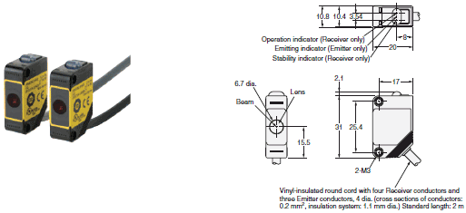
Pre-wired Cable with ABS Resin Case
E3FS-10B4 2M
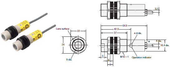
* Vinyl-insulated round cord with four Receiver conductors and three Emitter conductors, 4 dia. (cross sections of conductors: 0.2 mm2, insulation system: 1.1 mm dia.)
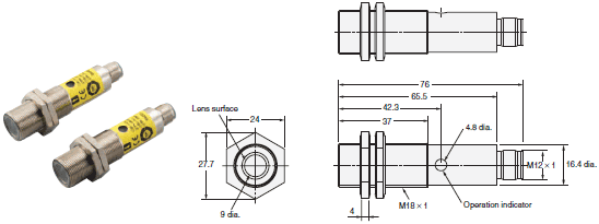
Connector with Metal Case
E3FS-10B4-M1-M
Accessories (Order Separately)
Branch Connector
F39-CN3

* The molded part B of the Connector is black.
Sensor Mounting Bracket (for E3FS)
Y92E-B18
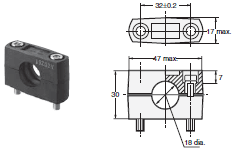
Material: Plastic
Hexagonal bolt: M5 x 32
Sensor Mounting Bracket (for E3ZS)
E39-L104
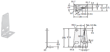
Material: Stainless steel (SUS304)
Cables with Connectors (Socket and Plug) on Both Ends (for extension)

XS2W-D421-C81-F (L=1m)
XS2W-D421-D81-F (L=2m)
XS2W-D421-G81-F (L=5m)
XS2W-D421-J81-F (L=10m)
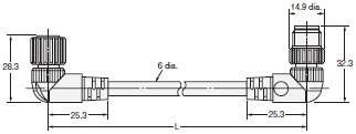
XS2W-D422-D81-F (L=2m)
XS2W-D422-G81-F (L=5m)
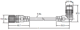
XS2W-D423-D81-F (L=2m)
XS2W-D423-G81-F (L=5m)

XS2W-D424-D81-F (L=2m)
XS2W-D424-G81-F (L=5m)
Sheath material: PVC
Cables with Connector (Socket) on One End (connecting to G9SP)

XS2F-D421-C80-F (L=1m)
XS2F-D421-D80-F (L=2m)
XS2F-D421-G80-F (L=5m)
XS2F-D421-J80-F (L=10m)
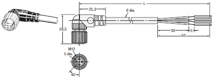
XS2F-D422-C80-F (L=1m)
XS2F-D422-D80-F (L=2m)
XS2F-D422-G80-F (L=5m)
XS2F-D422-J80-F (L=10m)
Sheath material: PVC
Connector Plug Assemblies, Solder Type
XS2G-D425

XS2G-D426

Connector Plug Assemblies, Screw-on Type
XS2G-D4S5

XS2G-D4S6

last update: April 21, 2016
OMRON E3ZS, E3FS lineup
E3ZS, E3FS Single-beam Safety Sensor/Lineuplast update: September 01, 2016
Sensors
| Sensor method | Appearance | Case material | Sheath material | Connection method | Sensing distance | Output | Model |
|---|---|---|---|---|---|---|---|
| Through- beam |  | Polybutylene terephthalate | PVC | Pre-wired cable (2 m) | 0.2 to 3 m (Red light) | PNP | E3ZS-T81A |
 | ABS | 10 m (Infrared light) | E3FS-10B4 2M * | ||||
 | Brass | --- | M12 connector | 10 m (Infrared light) | E3FS-10B4-M1-M * |
* Manufacturing has been discontinued.
Controller
Safety Controller G9SP Series
| Name | No. of I/O points | Unit version | Model | |||
|---|---|---|---|---|---|---|
| Safety inputs | Test outputs | Safety outputs | Standard outputs | |||
| Safety Controller | 10 | 4 | Semiconductor outputs: 4 | 4 | Ver.2.0 | G9SP-N10S |
| 10 | 6 | Semiconductor outputs: 16 | --- | G9SP-N10D | ||
| 20 | 6 | Semiconductor outputs: 8 | --- | G9SP-N20S | ||
Note: For details, refer to the G9SP Catalog (F090).
Accessories
Branch Connector
| Appearance | Model |
|---|---|
 | F39-CN3 |
Sensor Mounting Bracket (for E3FS)
| Appearance | Model |
|---|---|
 | Y92E-B18 |
Sensor Mounting Bracket (for E3ZS)
| Appearance | Model |
|---|---|
 | E39-L104 |
Mutual Interference Prevention Filter (for E3ZS)
| Dimensions | Model | Quantity | Remarks |
|---|---|---|---|
 | E39-E11 | 2 per Emitter and Receiver (4 total) | For use with E3ZS-T81A. This filter prevents mutual interference by changing the direction of polarized light of the 2 adjacent Emitter/ Receivers. However, when the filter is attached, the maximum sensing distance of the E3ZS is reduced to 1.5 m. |
Cables with Connectors (Socket and Plug) on Both Ends (for extension)
| Type | Cable connection direction | Cable length L (m) | DC | UL standard |
|---|---|---|---|---|
| Model | ||||
| Fire-retardant, robot cable | Straight/straight | 1 | XS2W-D421-C81-F | ● |
| 2 | XS2W-D421-D81-F | |||
| 5 | XS2W-D421-G81-F | |||
| 10 | XS2W-D421-J81-F | |||
| Right angle/right angle | 2 | XS2W-D422-D81-F | ||
| 5 | XS2W-D422-G81-F | |||
| Straight/right angle | 2 | XS2W-D423-D81-F | ||
| 5 | XS2W-D423-G81-F | |||
| Right angle/straight | 2 | XS2W-D424-D81-F | ||
| 5 | XS2W-D424-G81-F |
Note: Extend the cable under the following conditions.
• Overall cable length for both an E3FS Receiver connected to an G9SP and the Emitter connected to the G9SP
must be within 50 m.
• Overall cable length for both an E3ZS Receiver connected to an G9SP and the Emitter connected to the G9SP
must be within 100 m.
Cables with Connector (Socket) on One End (connecting to G9SP)
| Type | Cable connection direction | Cable length L (m) | DC | UL standard |
|---|---|---|---|---|
| Model | ||||
| Fire-retardant, robot cable | Straight | 1 | XS2F-D421-C80-F | ● |
| 2 | XS2F-D421-D80-F | |||
| 5 | XS2F-D421-G80-F | |||
| 10 | XS2F-D421-J80-F | |||
| Right angle | 1 | XS2F-D422-C80-F | ||
| 2 | XS2F-D422-D80-F | |||
| 5 | XS2F-D422-G80-F | |||
| 10 | XS2F-D422-J80-F |
Note: Extend the cable under the following conditions.
• Overall cable length for both an E3FS Receiver connected to an G9SP and the Emitter connected to the G9SP
must be within 50 m.
• Overall cable length for both an E3ZS Receiver connected to an G9SP and the Emitter connected to the G9SP
must be within 100 m.
Connector Plug Assemblies, Solder Type *
| Applicable cable diameter (mm) | Cable connection direction | Connection method | Model |
|---|---|---|---|
| 3 dia. (3 to 4 dia.) | Straight | Solder | XS2G-D425 |
| Right angle | XS2G-D426 |
* Use when connecting an E3ZS-T81A or E3FS-10B4 2M to an F39-CN3 Branch Connector.
Connector Plug Assemblies, Screw-on Type *
| Applicable cable diameter (mm) | Cable connection direction | Connection method | Model |
|---|---|---|---|
| 3 dia. (3 to 4 dia.) | Straight | Screw-on | XS2G-D4S5 |
| Right angle | XS2G-D4S6 |
* Use when connecting an E3ZS-T81A or E3FS-10B4 2M to an F39-CN3 Branch Connector.
last update: September 01, 2016
OMRON E3ZS, E3FS catalog
E3ZS, E3FS Single-beam Safety Sensor/Catalog- Catalog
- Manual
- CAD
English
Global Edition
| Catalog Name | Catalog Number [size] | Last Update | |
|---|---|---|---|
| | - [2105KB] | Sep 01, 201620160901 | E3ZS, E3FS Data Sheet |
- NO. E3ZS, E3FS
- TYPE:Safety Sensors
 Copyright Statement
  Copyright Statement
 - DATE:2021-06-12
- Associated products:
A7PS / A7PH Thumbwheel Switch/Features OS32C Safety Laser Scanner/Features