OMRON CJ1W-PTSAutomation Systems/ Programmable Controllers/CJ1
OMRON CJ1W-PTS Automation Systems
OMRON CJ1W-PTS Dimensions
/Images/l_1644-25-118586-198x198.jpglast update: December 19, 2013
• Supports a maximum of four inputs in one Unit: resistance thermometer, thermocouple, and DC current/voltage. (The input type is set separately for each input.)
• Isolation between input channels prevents unwanted current paths between input channels.
• Scaled values are transferred to the CPU Unit in four digits hexadecimal with voltage/current inputs.
• Process value alarm with two alarms for each input
• Alarm ON-delay timer and hysteresis for process value
• Zero/Span adjustment capability during operation
• Input error detection
• Maximum or minimum process value can be specified for when an input error is detected.
• A Unit with fully universal inputs, high-speed and high-resolution (256,000 resolution, 60 ms/ch is available.)
last update: December 19, 2013
Purchase the OMRON CJ1 Please fill in the following
If you have just landed here, this product OMRON CJ1W-PTS Automation Systems,Automation Systems is offered online by Tianin FLD Technical Co.,Ltd. This is an online store providing Automation Systems at wholesale prices for consumers. You can call us or send enquiry, we would give you the prices, packing,deliverty and more detailed information on the CJ1W-PTS We cooperate with DHL,TNT,FEDEX,UPS,EMS,etc.They guarantee to meet your needs in terms of time and money,even if you need your OMRON CJ1W-PTSAutomation Systems tomorrow morning (aka overnight or next day air) on your desk, 2, 3 days or more.Note to international customers, YES, we ship worldwide.
E3FA, E3RA, E3FB, E3RB Photoelectric Sensors/Features
E6C2-C Slim Incremental 50-mm-dia. Rotary Encoder/Features
61F-G[]N Floatless Level Switch (Compact Type)/Features
CJ1W-MD CJ-series Mixed I/O Units/Features
KM-N2-FLK Power Monitor/Features
OMRON CJ1W-PTS dimension
CJ1W-PTS CJ-series Process Analog I/O Unit/Dimensionslast update: April 01, 2014
CJ1W-PTS15
CJ1W-PTS51
CJ1W-PTS52
last update: April 01, 2014
OMRON CJ1W-PTS catalog
CJ1W-PTS CJ-series Process Analog I/O Unit/Catalog- Catalog
- Manual
- CAD
English
Global Edition
| Catalog Name | Catalog Number [size] | Last Update | |
|---|---|---|---|
| | - [2136KB] | Aug 18, 201520150818 | CJ1W-PTS/PDC/PH41U/AD04U Data Sheet |
OMRON CJ1W-PTS lineup
CJ1W-PTS CJ-series Process Analog I/O Unit/Lineuplast update: April 01, 2014
International Standards
- The standards are abbreviated as follows: U: UL, U1: UL (Class I Division 2 Products for Hazardous Locations), C: CSA, UC: cULus, UC1: cULus (Class I Division 2 Products for Hazardous Locations), CU: cUL, N: NK, L: Lloyd, and CE: EC Directives.
- Contact your OMRON representative for further details and applicable conditions for these standards.
Process I/O Units
Isolated-type Thermocouple Input Units
| Unit classi- fica- tion | Product name | Input points | Signal range selec- tion | Signal range | Conver- sion speed (resolu- tion) | Accuracy (at ambient tempera- ture of 25 °C) | Ex- ternal con- nec- tion | No. of unit num- bers allo- cated | Current consump- tion (A) | Model | Stand- ards | |
|---|---|---|---|---|---|---|---|---|---|---|---|---|
| 5 V | 24 V | |||||||||||
| CJ1 Special I/O Units | Process Input Units (Iso- lated- type Thermo- couple Input Units)  | 2 inputs | Set sepa- rately for each input | Thermo- couple: B, E, J, K, L, N, R, S, T, U, WRe5- 26, PLII DC voltage: ± 100 mV | Conver- sion speed: 10 ms/ 2 inputs, Resolu- tion: 1/64,000 | Standard accuracy: ±0.05% of F.S. *1 | Remov- able terminal block | 1 | 0.18 | 0.06 *2 | CJ1W-PTS15 | UC1, CE |
| 4 inputs | Com- mon inputs | Thermo- couple: R, S, K, J, T, L, B | Conver- sion speed: 250 ms/ 4 inputs | Accuracy: (±0.3% of PV or ±1°C, whichever is larger) ±1 digit max. *3 | 0.25 | --- | CJ1W-PTS51 | |||||
Note: This unit cannot be used, with the Machine Automation Controller NJ-series.
*1. The accuracy depends on the sensors used and the measurement temperatures. For details, refer to the user's
manual.
*2. This is for an external power supply, and not for internal current consumption.
*3. L and −100°C or less for K and T are ±2°C±1 digit max., and 200°C or less for R and S is ±3°C±1 digit max. No
accuracy is specified for 400°C or less for B.
Isolated-type Resistance Thermometer Input Units
| Unit classi- fica- tion | Product name | Input points | Signal range selec- tion | Signal range | Conver- sion speed (resolu- tion) | Accuracy (at ambient tempera- ture of 25 °C) | Ex- ternal con- nec- tion | No. of unit num- bers allo- cated | Current consump- tion (A) | Model | Stand- ards | |
|---|---|---|---|---|---|---|---|---|---|---|---|---|
| 5 V | 24 V | |||||||||||
| CJ1 Special I/O Units | Process Analog Input Units (Iso- lated- type Resist- ance Thermo- couple Input Units)  | 4 inputs | Com- mon inputs | Resist- ance ther- mom- eter: Pt100, JPt100 | Conver- sion speed: 250 ms/ 4 inputs | Accuracy: ±0.3% of PV or ±0.8°C, whichever is larger, ±1 digit max. | Remov- able terminal block | 1 | 0.25 | - | CJ1W-PTS52 | UC1, CE |
Note: This unit cannot be used, with the Machine Automation Controller NJ-series.
* This is for an external power supply, and not for internal current consumption.
last update: April 01, 2014
OMRON CJ1W-PTS specification
CJ1W-PTS CJ-series Process Analog I/O Unit/Specificationslast update: April 01, 2014
CJ1W-PTS15 Isolated-type Thermocouple Input Unit
| Item | Specifications | |
|---|---|---|
| Model | CJ1W-PTS15 | |
| Applicable Controller | CJ Series | |
| Unit classification | CJ-series Special I/O Unit | |
| Mounting position | CJ-series CPU Rack or CJ-series Expansion Rack | |
| Maximum number of Units | 40 (within the allowable current consumption and power consumption range) | |
| Unit numbers | 00 to 95 (Cannot duplicate Special I/O Unit numbers.) | |
| Areas for data exchange with CPU Unit | Special I/O Unit Area (Operation Data) | 10 words/Unit Thermocouple Input Unit to CPU Unit: All process values, process value alarms (LL, L, H, HH), conversion data enabled flags, sensor errors. |
| DM Area words allocated to Special I/O Units (Setting parameter) | 100 words/Unit CPU Unit to Thermocouple Input Unit: Temperature sensor type, input range (user set), process value alarm setting (L, H), zero/span adjustment value. | |
| Expansion Control/ Monitor Area words (Expansion Operation Data) | 35 words/Unit CPU Unit to Thermocouple Input Unit: Hold function selection start/reset, adjustment period control, control bits Thermocouple Input Unit to CPU Unit: Adjustment period warnings/notices (for each input), peak and bottom values, top and valley values | |
| Expansion Setting Area words (Expansion Setting parameter) | 46 words/Unit CPU Unit to Thermocouple Input Unit: Expansion Setting Area settings, adjustment period control, peak and bottom detection, top and valley detection | |
| Number of temperature sensor inputs | 2 | |
| Temperature sensor type | The sensor type, input range, and scaling can be set individually for each of 2 inputs, which are each selectable from B, E, J, K, L, N, R, S, T, U, WRe5-26, PL II, and mV. | |
| Scaling | Data to be stored in the allocated words in the CIO area must be scaled (with the minimum and maximum values set by user) (2 inputs set separately). For example, data can be stored at 0% to 100%. | |
| Data storage in the CIO Area | The value derived from carrying out the following processing in order of the actual process data in the input range is stored in four digits hexadecimal (binary values) in the allocated words in the CIO Area. 1) Mean value processing → 2) Scaling → 3) Zero/span adjustment → 4) Output limits | |
| Accuracy (25 ° C) | ±0.05% (Depends on the Sensor used and the measured temperature. Refer to Accuracy by Sensor Type and Measured Temperature Range on Data Sheet for details.) | |
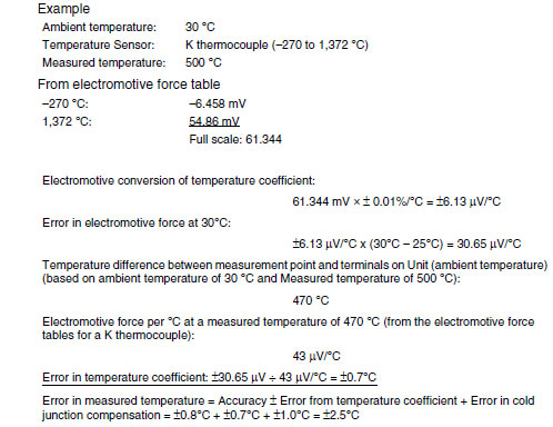
| Temperature coefficient | ±0.01%/°C (For full scale of electromotive force. *) | |
| Resolution | 1/64000 | |
| Cold junction compensation error | ±1°C, at 20 ±10°C | |
| Maximum signal input | ±120 mV | |
| Input impedance | 20 kΩ min. | |
| Input disconnection detection current | 0.1 μA (typical) | |
| Warmup time | 45 min | |
| Response time | 100 ms (travel time from input 0% to 90%, for ±100 mV step input and with moving average for 4 samples) | |
| Conversion period | 10 ms/2 inputs | |
| Maximum time to store data in CPU Unit | Conversion period + one CPU Unit cycle | |
| Disconnection detection | Detects disconnections at each input and turns ON the Disconnection Detection Flag. Hardware detection time: Approx. 0.5 s max. The process value overrange direction for when a disconnection occurs can be specified. (High: 115% of set input range; low: -15% of set input range) | |
| Function | Mean value processing (input filter) | Calculates the moving average for the specified number of process values (1 to 128), and stores that value in the CIO Area as the process value. |
| Process value alarm | Process value 4-point alarm (LL, L, H, HH), alarm hysteresis, and ON-delay timer (0 to 60 s) are available. | |
| Rate-of-change calculation | Calculates the amount of change per comparison time interval (1 to 16 s). | |
| Rate-of-change alarm | Rate-of-change 2-point alarm (L, H), alarm hysteresis (shared with process value alarm), and ON- delay timer (0 to 60 s, shared with process value alarm) are available. | |
| Adjustment period control | When zero/span adjustment is executed, the date is internally recorded at the Unit. When the preset zero/span adjustment period and number of days notice have elapsed (allocated in Expansion Setting Area), this function turns ON a warning flag to give notice that it is time for readjustment. | |
| Peak and bottom detection | This function detects the maximum (peak) and minimum (bottom) analog input values, from when the Hold Start Bit (output) allocated to the Expansion Control/Monitor Area turns ON until it turns OFF, and stores them in the Expansion Control/Monitor Area. | |
| Top and valley detection | This function detects the top and valley values for analog inputs, from when the Hold Start Bit (output) allocated to the Expansion Control/Monitor Area turns ON until it turns OFF, and stores them in the Expansion Control/Monitor Area. | |
| Isolation | Between inputs and Controller signals, and between inputs: Isolation by transformer for power supply, and by photocoupler for signals. Cold junction compensation circuit: No isolation from input 2 | |
| Insulation resistance | 20 MΩ (at 500 V DC) between inputs | |
| Dielectric strength | Between inputs: 1,000 V AC, at 50/60 Hz, for 1 min, leakage current 10 mA max. | |
| External connections | Terminal block (detachable) | |
| Unit number settings | Set by rotary switches on front panel, from 0 to 95. | |
| Indicators | Four LED indicators on front panel (for normal operation, errors detected at the Thermocouple Input Unit, errors related to the CPU Unit, and use of external power supply). | |
| Front panel connector | Sensor input connector terminal block (detachable) | |
| Effect on CPU Unit cycle time | 0.3 ms | |
| Current consumption | 5 V DC at 180 mA max. | |
| External power supply | 24 VDC +10%/-15% 60 mA max., inrush current: 20 A for 1 ms max. (The external 24-VDC power supply must be isolated.) | |
| Dimensions | 31 × 90 × 65 mm (W × H × D) | |
| Weight | 150 g max. | |
| Standard accessories | Two cold junction sensors (installed in terminal block) | |
* The method for calculating the error in temperature measurements, including the temperature coefficient, is given
below. The "full scale of electromotive force" is the difference between the high limit and low limit converted to
electromotive force for each thermocouple.
CJ1W-PTS51 Isolated-type Thermocouple Input Unit
| Item | Specifications | |
|---|---|---|
| Model | CJ1W-PTS51 | |
| Applicable Controller | CJ Series | |
| Unit classification | CJ-series Special I/O Unit | |
| Mounting position | CJ-series CPU Rack or CJ-series Expansion Rack | |
| Maximum number of Units | 40 (within the allowable current consumption and power consumption range) | |
| Unit numbers | 00 to 95 (Cannot duplicate Special I/O Unit numbers.) | |
| Areas for data exchange with CPU Unit | Special I/O Unit Area (Operation Data) | 10 words/Unit Thermocouple Input Unit to CPU Unit: All process values, process value alarms (L, H), conversion data enabled flag, sensor errors, cold junction sensor errors |
| DM Area words allocated to Special I/O Units (Setting parameter) | 100 words/Unit CPU Unit to Thermocouple Input Unit: Temperature sensor type, input range (same for all I/O), process value alarm setting (L, H), zero/span adjustment value. | |
| Number of temperature sensor inputs | 4 | |
| Temperature sensor types | Selectable from K, J, L, R, S, T, B. (Same setting for all inputs.) | |
| Data storage in the CIO Area | The actual process data in the input range is stored in four digits hexadecimal (binary or BCD values) in the allocated words in the CIO Area. | |
| Accuracy (25°C) | With Celsius selected: ±0.3% of PV or ±1°C, whichever is greater, ±1 digit max. With fahrenheit selected: ±0.3% of PV or ±2°F, whichever is greater, ±1 digit max. However, the accuracy of K and T at -100°C or lower and L is ±2°C ±1 digit max. The accuracy of R and S at 200°C or lower is ±3°C ± 1 digit max. The accuracy of B at 400°C or lower is not specified. PV: Process value data | |
| Temperature characteristics | Refer to Temperature Characteristics According to Thermocouple Type on Data Sheet. | |
| Warmup time | 30 min | |
| Conversion period | 250 ms/4 inputs | |
| Maximum time to store data in CPU Unit | Conversion period + one CPU Unit cycle | |
| Sensor error detection | Input Types Other Than B: A Sensor error is detected and the Sensor Error Flag is turned ON if the upper or lower limit of the set input range is exceeded by 20°C or 20°F. The process value overrange direction when a Sensor error occurs can be specified (high: set input range +20°C or +20°F, low: set input range -20°C or -20°F). B Input Type: A Sensor error is detected and the Sensor Error Flag is turned ON if the upper limit of 1,820°C or 3,220°F or the lower limit of 0°C or 0°F is exceeded. The process value overrange direction when a Sensor error occurs can be specified (high: set input range 1,820°C or 3,220°F, low: set input range 0°C or 0°F). | |
| Function | Process value alarm | Process value 2-point alarm (HH, H, LL, L), alarm hysteresis, and ON-delay timer (0 to 60 s) are available. External alarm outputs: One per input (H or L). |
| External alarm outputs | NPN outputs (with short-circuit protection) External power supply voltage: 20.4 to 26.4 V DC Max. switching capacity: 100 mA (for one output) Leakage current: 0.3 mA max. Residual voltage: 3 V max. | |
| Isolation | Between inputs and Controller signal: Transformer for power supply and photocoupler for signals Between each input: Transformer for power supply and photocoupler for signals. | |
| Insulation resistance | 20 MΩ max. (at 500 V DC). Between all output and NC terminals and external AC terminals (Power Supply Unit) Between all input terminals and external AC terminals (Power Supply Unit) Between all input terminals and all output terminals Between all external DC terminals (input, output, and NC terminals) and FG plate Between all input and output terminals and all NC terminals | |
| Dielectric strength | Between all output and NC terminals and external AC terminals (Power Supply Unit) 2,000 VAC, 50/60 Hz 1 min., detection current: 1 mA Between all input terminals and external AC terminals (Power Supply Unit) Between all input terminals and all output terminals Between all external DC terminals (input, output, and NC terminals) and FG plate 1,000 VAC, 50/60 Hz 1 min., detection current: 1 mA Between all channels 500 VAC, 50/60 Hz 1 min., detection current: 1mA | |
| External connections | Terminal block (detachable) | |
| Unit number settings | Set by rotary switches on front panel, from 0 to 95. | |
| Indicators | Seven LED indicators on front panel (for normal operation, errors detected at the Thermocouple Input Unit, errors related to the CPU Unit, and four indicators for external alarm outputs.) | |
| Current consumption (supplied from Power Supply Unit) | 5 V DC at 250 mA max. | |
| Dimensions | 31 × 90 × 65 mm (W × H × D) | |
| Weight | 150 g max. | |
CJ1W-PTS52 Isolated-type Resistance Thermometer Input Unit (Pt100, JPt100)
| Item | Specifications | |
|---|---|---|
| Model | CJ1W-PTS52 | |
| Applicable Controller | CJ Series | |
| Unit classification | CJ-series Special I/O Unit | |
| Mounting position | CJ-series CPU Rack or CJ-series Expansion Rack | |
| Maximum number of Units | 40 (within the allowable current consumption and power consumption range) | |
| Unit numbers | 00 to 95 (Cannot duplicate Special I/O Unit numbers.) | |
| Areas for data exchange with CPU Unit | Special I/O Unit Area (Operation Data) | 10 words/Unit Resistance Thermometer Input Unit to CPU Unit: All process values, process value alarms (L, H), conversion data enabled flags, sensor errors. |
| DM Area words allocated to Special I/O Units (Setting parameter) | 100 words/Unit CPU Unit to Resistance Thermometer Input Unit: Temperature sensor type, input range (user set), process value alarm setting (L, H), zero/span adjustment value. | |
| Number of temperature sensor inputs | 4 | |
| Temperature sensor type | Pt100 (JIS, IEC), JPt100 Sensor type, input range, and scaling to industrial units are the same for all I/O. | |
| Data storage in the CIO Area | The actual process data in the input range is stored in four digits hexadecimal (binary or BCD values) in the allocated words in the CIO Area. | |
| Accuracy (25 ° C) | ± 0.3% of PV or ± 0.8°C, whichever is greater, ± 1 digit max. ± 0.3% of PV or ± 1.6°F, whichever is greater, ± 1 digit max. PV: Process value data | |
| Temperature characteristics | Refer to Temperature Characteristics According to Platinum Resistance Thermometer Type on Data Sheet. | |
| Sensing method | 3-wire method | |
| Influence of conductor resistance | 0.4°C/Ω max. | |
| Warmup time | 10 min | |
| Conversion period | 250 ms/4 inputs | |
| Maximum time to store data in CPU Unit | Conversion period + one CPU Unit cycle | |
| Sensor error detection | Detects sensor error at each input and turns ON the Sensor error Flag. Hardware detection time: Approx. 0.5 s max. The process value overrange direction for when a sensor error occurs can be specified. (High: +20 digit of set input range; low: -20 digit of set input range) | |
| Function | Process value alarm | Process value 2-point alarm (H, L), alarm hysteresis, and ON-delay timer (0 to 60 s are available). |
| External alarm outputs | NPN outputs (with short-circuit protection) External power supply voltage: 20.4 to 26.4 V DC Max. switching capacity: 100 mA (for one output) Leakage current: 0.3 mA max. Residual voltage: 3 V max. | |
| Isolation | Between inputs and Controller signal: Transformer for power supply and photocoupler for signals Between each input: Transformer for power supply and photocoupler for signals | |
| Insulation resistance | 20 MΩ max. (at 500 V DC). Between all output and NC terminals and external AC terminals (Power Supply Unit) Between all input terminals and external AC terminals (Power Supply Unit) Between all input terminals and all output terminals Between all external DC terminals (input, output, and NC terminals) and FG plate Between all input and output terminals and all NC terminals | |
| Dielectric strength | Between all output and NC terminals and external AC terminals (Power Supply Unit) 2,000 V AC, 50/60 Hz 1 min., detection current: 1 mA Between all input terminals and external AC terminals (Power Supply Unit) Between all input terminals and all output terminals Between all external DC terminals (input, output, and NC terminals) and FG plate 1,000 V AC, 50/60 Hz 1 min., detection current: 1 mA Between all channels 500 VAC, 50/60 Hz 1 min., detection current: 1 mA | |
| External connections | Terminal block (detachable) | |
| Unit number settings | Set by rotary switches on front panel, from 0 to 95. | |
| Indicators | Seven LED indicators on front panel (for normal operation, errors detected at the Resistance Thermometer Input Unit, errors detected at the CPU Unit, and four indicators for external alarm outputs.) | |
| Current consumption | 5 V DC at 250 mA max | |
| Dimensions | 31 × 90 × 65 mm (W × H × D) Note: The height including the Backplane is 145 mm. | |
| Weight | 150 g max. | |
last update: April 01, 2014
- NO. CJ1W-PTS
- TYPE:Programmable Controllers CJ1 Special I/O Units
- DATE:2021-06-22
- Associated products:
CS1W-AT2[][] C200H I/O Terminal Block Conversion Adapter/Features CJ1G-CPU4[]P CJ Series Loop CPU Unit/Features