OMRON NSJ SeriesAutomation Systems/ Programmable Controllers/NSJ
OMRON NSJ Series Automation Systems
OMRON NSJ Series Dimensions
/Images/l_1751-25-118997-198x198.jpglast update: November 06, 2012
A Wide Selection of Scalable Display Controllers
(Product Line-up) Select the optimal control and display combination.
Four screen sizes are available, from 5.7 to 12.1 inches.

(NSJ Built-in Ethernet Port) Easy access to both Display Section and Controller Section
This allows PLC data to be read or written without adding an Ethernet Unit. PLC data can also be read or written, and alarms and recipes can be transferred, from a host computer.

Easy Access from a Host Computer
• Screen data and ladder programs can be easily transferred via Ethernet.
• PLC data can also be read by a host application (using FINS communications).

Easy Access to Other PLCs
• PLC2 data can be easily displayed and set from the NSJ (PLC1) display.

Note: It is also easy to allocate data from another host device for reference.
(Expansion Units) Support a wider range of applications.
Controller Link Unit (NSJW-CLK21-V1)
High-speed, large-capacity data link
The PLC data link function can be used to provide a high-speed, large-capacity data link between Controllers.

I/O Control Unit (NSJW-IC101)
Easy addition of Special I/O Units and CPU Bus Units
Used to mount Motion Control Units and other Special I/O Units or CPU Bus Units to the NSJ-series Controller, for excellent expandability.

Ethernet Unit (NSJW-ETN21)
Full use of versatile Ethernet functions
The NSJ built-in Ethernet port increases expandability with host computers by enabling functions such as communications implemented with CMND instructions and e-mail.

Note: For detailed information on functions related to the NSJ built-in Ethernet port and Ethernet Unit, refer to Catalog.
Meeting the Growing Needs for Control Panel Standardization

Effects of Standardizing Control Panels
Waste and inconsistency in design, installation and maintenance can be eliminated by supplying control panels that have the same basic operation regardless of the factory, the process, and the devices used in any country of the world.
1. Operating errors can be prevented by providing the same operability.
Reduce temporary lower operating efficiency caused by changing operators.
2. There is no need to produce an operating manual for each device.
Initial training cost can also be reduced.
3. Standardization greatly reduces the number of maintenance parts.
Even if a malfunction occurs, the entire control panel can be replaced as a module for quick and easy system
restoration.
4. Standardization makes it possible to create templates for design documents, screens, and ladder programs. This
increases the ability to reuse the templates, which greatly raises design efficiency.
Less Effort in Designing and Debugging
Advantages of One Package
Use of a single USB cable simplifies both design and debugging.
Use of a commercially available USB cable allows easy, high-speed transferring of screen data and ladder programs. There is also no need to change cables for transfers such as these.

(1) Power ON(2) Simply connect the USB cable and you are ready to transfer screen data and ladder programs.
Continue using your software assets.
Continue to use all the screen data for NS-series PTs and ladder programs for CS/CJ-series PLCs.

Simply turn ON the power and start using it. No need for initial settings.
There is no need to connect the Controller Section and Display Section, and no need to make initial communications settings or other settings.The system starts up as soon as the power is turned ON. Even the standard-equipped DeviceNet Master is completely set in the default settings.

The CX-One Integrated FA Tool Package Is Available
This software can be used to debug ladder programs and screens without even having to connect to an actual system.
The test functions of the CX-Designer Screen Designer for NS Series have been further strengthened. By selecting CX-Simulator as the connection destination, screen data and ladder programs can be simultaneously tested without even having to connect to an actual system.

The SAP Library, which dramatically reduces effort in design, has also been greatly expanded.
More than 2,000 Smart Active Parts (SAP) are available for directly accessing OMRON PLCs and components. Simply copy them from the library and paste them onto the screen. There is absolutely no need to design screens or ladder programs for these objects.

Less Effort in Maintenance
Two Troubleshooters Come as a Standard Feature
Enables a quick, on-site action without any software.
The standard-equipped PLC Troubleshooter and DeviceNet Troubleshooter contribute to solving problems during device startup and operation. When an error occurs, simply follow the on-screen instructions to confirm the error details and quickly implement countermeasures, without referring to the manual.
A Ladder Program Monitor Is Also Standard
Switching from the operation screen to the screen for monitoring PLC ladder programs only takes about 5 seconds.
This software lets you monitor PLC program status, search for addresses or instructions, monitor multiple I/O points, and much more. It only takes about 5 seconds to switch from a user screen to the ladder program monitoring screen. From a selected input bit, you can also search for the next sequence output instruction that uses the same address.

A Data Backup Function Is Also Standard
Easy backup without a computer.
Simply follow the on-screen instructions to back up both screen data and ladder programs for the Controller Section.

last update: November 06, 2012
Purchase the OMRON NSJ Please fill in the following
If you have just landed here, this product OMRON NSJ Series Automation Systems,Automation Systems is offered online by Tianin FLD Technical Co.,Ltd. This is an online store providing Automation Systems at wholesale prices for consumers. You can call us or send enquiry, we would give you the prices, packing,deliverty and more detailed information on the NSJ Series We cooperate with DHL,TNT,FEDEX,UPS,EMS,etc.They guarantee to meet your needs in terms of time and money,even if you need your OMRON NSJ SeriesAutomation Systems tomorrow morning (aka overnight or next day air) on your desk, 2, 3 days or more.Note to international customers, YES, we ship worldwide.
XW2Z-R Cables for I/O Relay Terminals/Features
R88M-G, R88D-GN[]-ML2 G-series AC Servomotors/Servo Drives with Built-in MECHATROLINK-II Communic...
TL-N / -Q Rectangular Standard Proximity Sensor/Features
TP70 On-site Flexible Rod Switch/Features
H3DK-M / -S Multi-range, Multi-mode Timer/Features
OMRON NSJ Series dimension
NSJ Series Programmable Controllers/Dimensionslast update: November 06, 2012
NSJ12-TS01(B)-G5D NSJ10-TV01(B)-G5D
NSJ8-TV01(B)-G5D
NSJ5-TQ11(B)-G5D
last update: November 06, 2012
OMRON NSJ Series catalog
NSJ Series Programmable Controllers/Catalog- Catalog
- Manual
- CAD
English
Global Edition
| Catalog Name | Catalog Number [size] | Last Update | |
|---|---|---|---|
| | V406-E1-05 [4786KB] | Apr 03, 201720170403 | NSJ Series Catalog |
| | - [232KB] | Jun 06, 201220120606 | HMC-EF183 Data Sheet |
OMRON NSJ Series lineup
NSJ Series Programmable Controllers/Lineuplast update: May 18, 2016
Controllers
NSJ[]-[][][][]-G5D
Controller Section I/O: 1280 points User program memory: 60 Ksteps Data memory: 128 Kwords (DM: 32 Kwords) Extended data memory: EM: 32 Kwords × 3 banks LD instruction execution time: 0.04 μs Number of Expansion Racks: 3 FB program memory (bytes): 1024 KB
| Name | Display Section | Built-in Ethernet port | Model number | Stand- ards | |||
|---|---|---|---|---|---|---|---|
| Display device | Case color | Effective display area | Resolution | ||||
| SYSMAC One NSJ- series NSJ Controller | 5.7-inch color High- luminance TFT LCD | Ivory | 117.2 × 88.4 mm (W × H) (5.7 inches) | 320 × 240 (QVGA) | Yes | NSJ5-TQ11-G5D | UC1, CE, UL Type 4 |
| Black | NSJ5-TQ11B-G5D | ||||||
| 8.4-inch color TFT LCD | Ivory | 170.9 × 128.2 mm (W × H) (8.4 inches) | 640 × 480 (VGA) | Yes | NSJ8-TV01-G5D | UC1, CE | |
| Black | NSJ8-TV01B-G5D | ||||||
| 10.4-inch color TFT LCD | Ivory | 215.2 × 162.4 mm (W × H) (10.4 inches) | Yes | NSJ10-TV01-G5D | UC1, CE UL Type4 | ||
| Black | NSJ10-TV01B-G5D | ||||||
| 12.1-inch color TFT LCD | Ivory | 246.0 × 184.5 mm (W × H) (12.1 inches) | 800 × 600 (SVGA) | Yes | NSJ12-TS01-G5D | ||
| Black | NSJ12-TS01B-G5D | ||||||
Note: Production of the NSJ[]-[][][][](B)-M3D, NSJ5-SQ1[](B)-G5D, NSJ5-TQ10(B)-G5D, NSJ8-TV00(B)-G5D,
NSJ10-TV00(B)-G5D and NSJ12-TS00(B)-G5D have been discontinued at the end of September 2012.
Options and Expansion Units
| Name | Specifications | Model | Standards | ||
|---|---|---|---|---|---|
| Expansion Units | NSJ Controller Link Unit | For increasing the number of Controller Link ports Same as the CJ1W-CLK21-V1 Controller Link Unit for the CJ Series. | NSJW-CLK21-V1 | UC1, CE | |
| NSJ Ethernet Unit | For increasing the number of Ethernet ports Same as the CJ1W-ETN21 Ethernet Unit for the CJ Series. | NSJW-ETN21 | |||
| NSJ I/O Control Unit | For adding CJ-series Expansion Racks. Same as the CJ1W-IC101 I/O Control Unit for the CJ Series. Use the following I/O Connecting Cables. | NSJW-IC101 | |||
| I/O Connecting Cables | For connecting CJ-series Expansion Racks. | 0.3 m | CS1W-CN313 | N, L, CE | |
| 0.7 m | CS1W-CN713 | ||||
| 2 m | CS1W-CN223 | ||||
| 3 m | CS1W-CN323 | ||||
| 5 m | CS1W-CN523 | ||||
| 10 m | CS1W-CN133 | ||||
| 12 m | CS1W-CN133-B2 | ||||
| Memory Cards (for both Controller Section and Display Section) | Flash memory: 128 MB | HMC-EF183 | N, L, CE | ||
| Flash memory: 256 MB | HMC-EF283 | ||||
| Flash memory: 512 MB | HMC-EF583 | ||||
| Memory Card Adapter (for computer PCMIA slot) | HMC-AP001 | CE | |||
| Peripheral Device Connecting Cables for the RS-232C port | Connects computer, D-Sub 9-pin, Length: 2.0 m | Used for peripheral bus or Host Link. Anti-static connectors | XW2Z-200S-CV | --- | |
| Connects computer, D-Sub 9-pin, Length: 5.0 m | XW2Z-500S-CV | ||||
| Connects computer, D-Sub 9-pin, Length: 2.0 m | Used for Host Link only. Peripheral bus not supported. | XW2Z-200S-V | |||
| Connects computer, D-Sub 9-pin, Length: 5.0 m | XW2Z-500S-V | ||||
| RS-422A Conversion Adapter | Adapter for converting a RS-232C port to a RS-422A/485 port. | Communications distance: 500 m max. | NS-AL002 | --- | |
| Communications distance: 50 m max. | CJ1W-CIF11 | UC1, CE, N, L | |||
| Battery life | 5 years at 25 °C | CJ1W-BAT01 | CE | ||
Differences between the NSJ[]-[][][][]-G5D and NSJ[]-[][][][]-M3D
| Model | NSJ[]-[][][][]-G5D | NSJ[]-[][][][]-M3D (The following models are discontinued.) |
|---|---|---|
| UM capacity | 60 Ksteps | 20 Ksteps |
| I/O | 1,280 points | 640 points |
| Extended data memory | 32 Kwords × 3 banks | None |
| EM file memory | Yes | None |
| Maximum number of Expansion Racks | 3 | 1 |
| FB program memory capacity | 1024 KB | 256 KB |
| Maximum number of FB definitions | 1024 | 128 |
| Maximum number of FB instances | 2048 | 256 |
| Variable table size | 128 KB | 64 KB |
Support Software
| Product name | Specifications | Model | Stand- ards | ||
|---|---|---|---|---|---|
| Number of licenses | Media | ||||
| FA Integrated Tool Package CX-One Ver.4.[] | The CX-One is a comprehensive software package that integrates Support Software for OMRON PLCs and components. CX-One runs on the following OS. Windows XP (Service Pack 3 or higher, 32-bit version)/ Windows Vista (32-bit/64-bit version)/ Windows 7 (32-bit/64-bit version)/ Windows 8 (32-bit/64-bit version)/ Windows 8.1 (32-bit/64-bit version)/ Windows 10 (32-bit/64-bit version) CX-One Ver.4.[] includes CX-Designer Ver.3.[]. For details, refer to the CX-One catalog (Cat. No. R134). | 1 licence * | DVD | CXONE-AL01D-V4 | --- |
Note: Multi licenses (3, 10, 30, or 50 licenses) and DVD media without licenses are also available for the CX-One.
last update: May 18, 2016
OMRON NSJ Series specification
NSJ Series Programmable Controllers/Specificationslast update: April 3, 2017
General Specifications
Parts Names
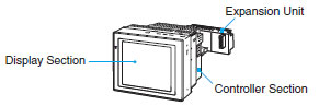
NSJ Controllers
| Model | Specifications | ||||
|---|---|---|---|---|---|
| NSJ12-TS01-G5D | NSJ10-TV01-G5D | NSJ8-TV01-G5D | NSJ5-TQ11-G5D | ||
| Supply voltage | 24 VDC | ||||
| Allowable supply voltage range | 20.4 to 27.6 VDC (24 VDC ± 15%) | ||||
| Power consumption | 30 W max. | TQ1[]: 22 W max. | |||
| Current consumption | Controller Section Internal 5 V: 500 mA max. DeviceNet Section Internal 5 V: 200 mA max., External 24 V: 18 mA max. | ||||
| Inrush current *1 | At 24 VAC: 10 A/20 ms max. for cold start at room temperature | ||||
| Ambient operating temperature (depending on angle of display surface off horizontal) *2 | 90 ° to 60 °: 0 to 50 °C 60 ° to 30 °: 0 to 45 °C 30 ° to 0 °: Use prohibited. | 90 ° to 30 °: 0 to 50 °C 30 ° to 0 °: 0 to 40 °C | |||
| Ambient storage temperature | - 20 to 60 °C | ||||
| Ambient operating humidity | 0 to 40 °C: 35% to 85% (with no condensation) 40 to 50 °C: 35% to 60% (with no condensation) | ||||
| Ambient operating environment | No corrosive gases | ||||
| Insulation resistance | 20 MΩ min. (at 100 VDC) between DC external and GR terminals | ||||
| Dielectric strength | 800 VDC for 1 min between DC external and GR terminals, leakage current: 10 mA max. | ||||
| Noise immunity | 2 kV on power supply line (conforming to IEC 61000-4-4) | ||||
| Vibration resistance (during operation) | 10 to 57 Hz, 0.075-mm amplitude, 57 to 150 Hz, acceleration: 9.8 m/s2 in X, Y, and Z directions for 80 minutes | ||||
| Shock resistance (during operation) | 147 m/s2, 3 times each in X, Y, and Z directions | ||||
| External dimensions *3 | Without Expansion Unit | 315 × 241 × 73.3 mm (W × H × D) | 232 × 177 × 73.3 mm (W × H × D) | 195 × 142 × 79 mm (W × H × D) | |
| With Expansion Unit | 315 × 241 × 89.3 mm (W × H × D) | 232 × 177 × 89.3 mm (W × H × D) | 195 × 142 × 95 mm (W × H × D) | ||
| Panel cutout dimensions | 302 +0.1, 0 × 228 +0.1, 0 mm (W × H) Panel thickness: 1.6 to 4.8 mm | 220.5 +0.50, 0 × 165.5 +0.50, 0 mm (W × H) Panel thickness: 1.6 to 4.8 mm | 184 +0.50, 0 × 131 +0.50, 0 mm (W × H) Panel thickness: 1.6 to 4.8 mm | ||
| Grounding | 100 Ω or less | ||||
| Weight | 2.7 kg max. | 2.5 kg max. | 2.0 kg max. | 1.1 kg max. | |
| Degree of protection | Front operating panel: Equivalent to IP65 Oil-proof type and NEMA4 *4 | Front operating panel: Equivalent to IP65 Oil-proof type, NEMA4 and UL Type 4 *4 | |||
| Battery life | 5 years (at 25°C) The SRAM and RTC will be backed up for 5 days after the battery runs low (i.e., after the indicator lights orange). The SRAM and RTC will be backed up by a super capacitor for 5 minutes after removing the old battery (i.e., after turning ON power after 5 minutes). | ||||
| International standards | Conforms to cULus and EC Directives. | ||||
*1. A delay circuit that charges a capacitor is used to limit the inrush current. If a hot start is performed when the power
supply has been OFF only a short period of time, the capacitor will still be charged and the inrush current specified
above will be exceeded by up to approximately five times the specified value. When selecting fuses or breakers for
external circuits, allow sufficient margin in the melting temperatures, detection characteristics, and inrush current
*2. Display angles off horizontal are as follows:

*3. For detailed information, refer to “Dimensions”.
*4. May not be applicable in locations with long-term exposure to oil.
NSJ Expansion Units
Controller Link Unit
| Item | Specifications |
|---|---|
| Model | NSJW-CLK21-V1 |
| Current consumption | 300 mA |
| Weight | 100 g max. |
Note: Other general specifications are the same as the NSJ Controller.
Ethernet Unit
| Item | Specifications |
|---|---|
| Model | NSJW-ETN21 |
| Current consumption | 370 mA |
| Weight | 100 g max. |
Note: Other general specifications are the same as the NSJ Controller.
I/O Control Unit
| Item | Specifications |
|---|---|
| Model | NSJW-IC101 |
| Current consumption | 20 mA |
| Weight | 100g max. |
Note: Other general specifications are the same as the NSJ Controller.
Controller Section Specifications
| Item | Specifications | |||
|---|---|---|---|---|
| Control method | Stored program | |||
| I/O control method | Cyclic scan and immediate processing are both possible. | |||
| Programming | Ladder diagram | |||
| CPU processing modes | Normal Mode, Parallel Processing Mode with Asynchronous Memory Access, Parallel Processing Mode with Synchronous Memory Access, and Peripheral Servicing Priority Mode | |||
| Instruction length | 1 to 7 steps per instruction | |||
| Ladder instructions | Approx. 400 (3-digit function codes) | |||
| Execution time | Basic instructions | 0.04 μs min. | ||
| Special instructions | 0.06 μs min. | |||
| Overhead time | Normal mode: 0.3 ms Parallel processing: 0.3 ms | |||
| Installation | Installed using Panel Mounting Bracket. | |||
| Mountable Expansion Units | One of the following can be mounted as an Expansion Unit: NSJ I/O Control Unit (NSJW-IC101) NSJ Controller Link Unit (NSJW-CLK21-V1) NSJ Ethernet Unit (NSJW-ETN21) | |||
| Maximum number of Expansion Racks | With the NSJW-IC101 I/O Control Unit mounted, a maximum of three CJ-series Expansion Racks can be used with the NSJ[]-[][][][](B)-G5D. A CJ-series CJ1W-II101 Interface Unit and Power Supply Unit are required for each Expansion Rack. | |||
| Maximum number of connectable Units | Per Expansion Rack: 10 Units max. (Basic I/O Units, Special I/O Units, or CPU Bus Units) A maximum of 30 Units (10 Units on CJ-series Expansion Rack × 3) can be mounted to the entire NSJ[]-[][][][](B)-G5D system. | |||
| Number of tasks | 288 (cyclic tasks: 32, interrupt tasks: 256) Interrupt tasks can be defined as cyclic tasks called "extra cyclic tasks." Including these, up to 288 cyclic tasks can be used. Note 1. Cyclic tasks are executed each cycle and are controlled with TKON(820) and TKOF(821) instructions. Note 2. The following 3 types of interrupt tasks are supported: Power OFF interrupt task: 1 max., Scheduled interrupt tasks: 2 max., External interrupt tasks: 256 max. | |||
| Interrupt types | Scheduled Interrupts: Interrupts generated at a time scheduled by the Controller Section's built-in timer. (See note. 1) Power OFF Interrupt (See note 2.): Interrupt executed when the Controller Section's power is turned OFF. External I/O Interrupts: Interrupts from the Special I/O Units or CPU Bus Units. Note 1. Scheduled interrupt time interval is either 1 ms to 9,999 ms or 10 ms to 99,990 ms, in units of 1 ms or 10 ms. Note 2. Not supported when the CJ1W-PD022 Power Supply Unit is mounted. | |||
| Calling subroutines from more than one task | Supported using global subroutines. | |||
| Function blocks | Languages supported in function block definitions: Ladder programming language and structured text | |||
| CIO (Core I/O) Area | I/O Area | 2,560 (160 words): CIO 000000 to CIO 015915 (words CIO 0000 to CIO 0159) The setting of the first rack word can be changed from the default (CIO 0000) so that CIO 0000 to CIO 0999 can be used. I/O bits are allocated to Basic I/O Units. | The CIO Area can be used as work bits if the bits are not used as shown here. | |
| Link Area | 3,200 (200 words): CIO 10000 to CIO 119915 (words CIO 1000 to CIO 1199) | |||
| CPU Bus Unit Area | 6,400 (400 words): CIO 150000 to CIO 189915 (words CIO 1500 to CIO 1899) CPU Bus Unit bits store operating status of CPU Bus Units. (25 words per Unit, 16 Units max.) | |||
| Inner Board Area | 1,600 (100 words): CIO 190000 to CIO 199915 (words CIO 1900 to CIO 1999) Bits in the Inner Board Area are allocated to the display status area. | |||
| C200H Special I/O Unit Area | 15,360 (960 words): CIO 200000 to CIO 295915 (words CIO 2000 to CIO 2959) Bits in the Special I/O Area can be allocated to Special I/O Units (10 words per Unit, 96 Units max.) | |||
| DeviceNet Area | 9,600 (600 words): CIO 320000 to CIO 379915 (words CIO 3200 to CIO 3799) DeviceNet bits are allocated to Slaves for DeviceNet Section remote I/O communications when the master function is used with fixed allocations. Fixed allocation setting 1 Outputs: CIO 3200 to CIO 3263 Inputs: CIO 3300 to CIO 3363 Fixed allocation setting 2 Outputs: CIO 3400 to CIO 3463 Inputs: CIO 3500 to CIO 3563 Fixed allocation setting 3 Outputs: CIO 3600 to CIO 3663 Inputs: CIO 3700 to CIO 3763 Note: The following words are allocated to the master function even when the DeviceNet Unit is used as a slave. Fixed allocation setting 1 Outputs: CIO 3370 (master to slave) Inputs: CIO 3270 (slave to master) Fixed allocation setting 2 Outputs: CIO 3570 (master to slave) Inputs: CIO 3470 (slave to master) Fixed allocation setting 3 Outputs: CIO 3770 (master to slave) Inputs: CIO 3670 (slave to master) | |||
| Work bits | CIO (Core I/O) Area | 4,800 (300 words): CIO 120000 to CIO 149915 (words CIO 1200 to CIO 1499) 37,504 (2,344 words): CIO 380000 to CIO 614315 (words CIO 3800 to CIO 6143) These bits in CIO Area are used as work bits in programming to control program execution. They cannot be used for external I/O. | ||
| Work Area | 8,192 bits (512 words): W00000 to W51115 (words W000 to W511) Control programs only. (I/O from external I/O terminals is not possible.) Note: When using work bits in programming, use bits in Work Area first before using bits from other areas. | |||
| Holding Area | 8,192 bits (512 words): H00000 to H51115 (words H000 to H511) Holding bits are used to control execution of program, and maintain their ON/OFF status when the PLC is turned OFF or operating mode is changed. Note: Words H512 to H1535 are allocated to the Function Block Holding Area and are used only for the function block instance area (internally allocated variable area). | |||
| Auxiliary Area | Read only: 7,168 bits (448 words): A00000 to A44715 (words A000 to A447) Read/write: 8,192 bits (512 words): A44800 to A95915 (words A448 to A959) Auxiliary bits are allocated specific functions. | |||
| Temporary Area | 16 bits (TR00 to TR15) Temporary bits are used to store ON/OFF execution conditions at program branches. | The bits on the left can be used as work bits when they are not used for their normal application | ||
| Timer Area | 4,096: T0000 to T4095 (used for timers only) | |||
| Counter Area | 4,096: C0000 to C4095 (used for counters only) | |||
| DM Area | 32 Kwords: D00000 to D32767 | Used as a general-purpose data area for reading and writing data in word units (16 bits). Words in the DM Area maintain their status when the NSJ Controller is turned OFF or the operating mode is changed. | ||
| Special I/O Unit DM Area: D20000 to D29599 (100 words × 96 Units). | Used to set parameters for Special I/O Units. | |||
| CPU Bus Unit DM Area: D30000 to D31599 (100 words × 16 Units). | Used to set parameters for CPU Bus Units. | |||
| EM Area | NSJ[]-[][][][](B)-G5D: 32 Kwords per bank, 3 banks max.: E0_00000 to E2_32767 max. Used as a general-purpose data area for reading and writing data in word units (16 bits). Words in EM Area maintain their status when the NSJ Controller is turned OFF or operating mode is changed. The EM Area is divided into banks, and addresses can be set by either of following methods. Changing current bank using the EMBC (281) instruction and setting addresses for the current bank. Setting bank numbers and addresses directly. EM data can be stored in files by specifying number of first bank. (EM file memory) | |||
| Index Registers | IR0 to IR15. Store actual memory addresses for indirect addressing. Index registers can be used independently in each task. One register is 32 bits (2 words). Index registers can be specified as shared or independent for each task. | |||
| Task Flag Area | 32 (TK0000 to TK0031). Task Flags are read-only flags that are ON when corresponding cyclic task is executable and OFF when corresponding task is not executable or in standby status. | |||
| Trace Memory | 4,000 words (traceable data: 31 bits and 6 words) | |||
| File Memory | Memory Cards: Compact flash memory cards can be used (MS-DOS format). EM file memory: Part of EM Area can be converted to file memory (MS-DOS format). The NSJ[]-[][][][](B)-M3D does not support EM file memory. | |||
| Functions | Constant cycle time | 1 to 32,000 ms (Unit: 1 ms) Note: Using the Parallel Processing Mode will create a constant cycle time for program execution. | ||
| Cycle time monitoring | Possible (Unit stops operating if cycle is too long): 10 to 40,000 ms (Unit: 10 ms) Note: When the Parallel Processing Mode is used, the program execution cycle is monitored. Controller Section operation will stop if the peripheral servicing time exceeds 2 s. | |||
| I/O refreshing | Cyclic refreshing, immediate refreshing, refreshing by IORF(097). Note: IORF(097) refreshes I/O bits allocated to Basic I/O Units and Special I/O Units. The CPU BUS UNIT I/O REFRESH (DLNK(226)) instruction can be used to refresh bits allocated to CPU Bus Units in the CIO and DM Areas. | |||
| Timing of refreshing for CPU Bus Units | Data links for Control Link Units, remote I/O communications for DeviceNet Units, and other special data for CPU Bus Units is refreshed at the following times. During I/O refresh period or when CPU BUS UNIT I/O REFRESH (DLNK(226)) instruction is executed. | |||
| I/O memory holding when changing operating modes | Depends on ON/OFF status of IOM Hold Bit in Auxiliary Area. | |||
| Load OFF | All outputs on Output Units can be turned OFF when the Controller Section is operating in RUN, MONITOR, or PROGRAM mode. | |||
| Timer/counter PV refresh method | BCD or binary (CX-Programmer version 3.0 or higher) | |||
| Input time constant setting | Time constants can be set for inputs from CJ-series Basic I/O Units. The time constant can be increased to reduce influence of noise and chattering or it can be decreased to detect shorter pulses on inputs. | |||
| Mode setting at power-up | The operating mode can be specified. | |||
| Flash memory | The user program and parameter area data (e.g., PLC Setup) are always backed up automatically in flash memory. (automatic backup and restore.) When downloading projects from CX-Programmer Ver. 5.0 or higher, symbol table files (including CX-Programmer symbol names, I/O comments), comment files (CX-Programmer rung comments, other comments), and program index files (CX-Programmer section names, section comments, or program comments) are stored in comment memory within the flash memory. | |||
| Memory Card functions (Controller Section) | Automatically reading programs (autoboot) from the Memory Card when the power is turned ON. | Possible | ||
| Program replacement during Controller Section operation | Possible | |||
| Memory Card storage data | User program: Program file format PLC Setup and other parameters: Data file format I/O memory: Data file format (binary), text format, CSV format | |||
| Memory Card read/write method | User program instructions, Programming Devices (including CX-Programmer and Programming Console), Host Link computers, Auxiliary Area control bits, easy backup operation | |||
| Filing (Controller Section) | Memory Card data and EM (Extended Data Memory) Area can be handled as files. | |||
| Debugging | Force-set/reset, differential monitoring, data tracing (scheduled, each cycle, or when instruction is executed), storing location generating error. | |||
| Online editing | User programs can be overwritten in program block units when the Controller Section is in MONITOR or PROGRAM mode. This function is not supported for block programming areas. With the CX-Programmer, more than one program block can be edited at the same time. | |||
| Program protection | Overwrite protection: Set using DIP switch or via the password from CX-Programmer peripheral device. Copy protection: Password set using CX-Programmer. | |||
| Error check | User-defined errors (i.e., user can define fatal errors and non-fatal errors) The FPD(269) instruction can be used to check execution time and logic of each programming block. Note: FAL and FALS instructions can be used to simulate errors. | |||
| Error log | Up to 20 errors are stored in error log. Information includes error code, error details, and time error occurred. Note: The Controller Section can be set so that user-defined FAL errors are not stored in the error log. | |||
| Clock | Provided on all models. Accuracy: | |||
| Ambient temperature | Monthly variation | |||
| 25°C | -1.5 to +1.5 min | |||
| Note 1. Accuracy varies with the temperature. Note 2. Used to store time when power is turned ON and when errors occur. | ||||
| Power OFF detection time | 2 ms | |||
| Power OFF detection delay time | 0 ms fixed | |||
| Memory protection | Held Areas: Holding bits, Data Memory, Extended Data Memory, and status of counter Completion Flags and present values. Note: If IOM Hold Bit in Auxiliary Area is turned ON, and PLC Setup is set to maintain IOM Hold Bit status when power to the NSJ Controller is turned ON, contents of CIO Area, Work Area, part of Auxiliary Area, timer Completion Flag and present values, Index Registers, and Data Registers will be saved. | |||
| Sending commands to a Host Link computer | FINS commands can be sent to a computer connected via Host Link System by executing Network Communications Instructions from the Controller Section. | |||
| Remote programming and monitoring | Host Link communications can be used for remote programming and remote monitoring through a Controller Link System or Ethernet network. | |||
| Eight-level communications | Host Link communications can be used for remote programming and remote monitoring from devices on networks up to eight levels away (Controller Link Network, Ethernet Network, or other network). | |||
| Storing comments in CPU Unit | I/O comments can be stored as symbol table files in Memory Cards in the Controller Section, EM file memory, or Comment Memory (see note). Note: Supported for CX-Programmer Ver. 5.0 or later only. | |||
| Program check | Program checks are performed at the beginning of operation for items such as no END(001) instruction and instruction errors. CX-Programmer can also be used to check programs. | |||
| Battery life | 5 years at 25 °C (The battery life depends on the ambient operating temperature; 1.1 years min.) (Battery set: CJ1W-BAT01; Use a Replacement Battery that is within two years of its date of manufacture.) | |||
| Self-diagnostics | Controller Section errors (watchdog timer), I/O bus errors, memory errors, and battery errors | |||
| Other functions | Storage of number of times power has been interrupted. (Stored in A514.) | |||
Display Section Specifications
| Model | Built-in ports | ||||
|---|---|---|---|---|---|
| USB port (Slave: For Support Software) | RS-232C port | DeviceNet port | Ethernet port | USB port (Host: For printer) | |
| NSJ5-TQ11-G5D | 1 port | 3 ports Display Section: Serial ports A, B Controller Section: Serial port | 1 port | 10/ 100Base-T | None |
| NSJ5-TQ11B-G5D | |||||
| NSJ8-TV01-G5D | 10/ 100Base-T | 1 port | |||
| NSJ8-TV01B-G5D | |||||
| NSJ10-TV01-G5D | 10/ 100Base-T | ||||
| NSJ10-TV01B-G5D | |||||
| NSJ12-TS01-G5D | 10/ 100Base-T | ||||
| NSJ12-TS01B-G5D | |||||
| Model | Display Section | |||
|---|---|---|---|---|
| Display color | Field of view | Language | Standard screen data capacity | |
| NSJ5-TQ11-G5D | 256 colors (BMP/JPEG, 32,768 colors for images) | Right/left: ±80°, Top: 80°, Bottom: 60° *1 | Eight languages *2 | 60 MB |
| NSJ5-TQ11B-G5D | ||||
| NSJ8-TV01-G5D | Right/left: ±80°, Top: 80°, Bottom: 60° *1 | |||
| NSJ8-TV01B-G5D | ||||
| NSJ10-TV01-G5D | Right/left: ±70°, Top: 65°, Bottom: 65° *1 | |||
| NSJ10-TV01B-G5D | ||||
| NSJ12-TS01-G5D | Right/left: ±80°, Top: 80°, Bottom: 80° *1 | |||
| NSJ12-TS01B-G5D | ||||
*1. LotNo.15Z10 or later of NS5 models, LotNo. 28X11 or later of NS8 models, LotNo. 11Y11 or later of NS10 models,
LotNo. 14Y11 or later of NS12 models.
*2. Japanese, English, Chinese (traditional and simplified), Spanish, Italian, German, and French.
Communications Section Specifications
DeviceNet Section
| Item | Specifications | |||
|---|---|---|---|---|
| Communications protocol | DeviceNet | |||
| DeviceNet master/slave | Can function as master or slave. | |||
| Connection forms *1 | Combination of multi-drop and T-branch connections (for trunk or branch lines) | |||
| Terminating resistance | SW4 (TER) is used to connect/disconnect terminating resistance. The TER indicator lights when terminating resistance is connected. | |||
| Baud rate | 500 kbps, 250 kbps, or 125 kbps (Set via DIP switch.) | |||
| Communications distances | Baud rate | Network length | Branch line length | Total branch line length |
| 500 kbps | 100 m max. | 6 m max. | 39 m max. | |
| 250 kbps | 250 m max. *2 | 6 m max. | 78 m max. | |
| 125 kbps | 500 m max. *2 | 6 m max. | 156 m max. | |
| Max. number of Slaves | 63 Slaves | |||
| Error control | CRC error check, node address redundancy check, scan list verification | |||
| Cable | Special 5-wire cable (2 signal lines, 2 power lines, 1 shield line) | |||
*1. Terminating resistance is required at both ends of the trunk line.
*2. Communications distances are for Thick Cables. Keep the maximum network length to 100 m or less when using
Thin Cables.
Controller Link (Wired)
| Item | Specifications |
|---|---|
| Communications method | N: N token bus |
| Code | Manchester code |
| Modulation | Baseband code |
| Synchronization | Flag synchronization (conforms to HDLC frames) |
| Error control | Manchester code checks and CRC checks (CCITT X16 +X12 +X5 +1) |
| Transmission path form | Multi-drop bus |
| Baud rate and maximum transmission distance | The maximum transmission distance varies with the baud rate as follows: 2 Mbps: 500 m 1 Mbps: 800 m 500 Kbps: 1 km |
| Media | Specified shielded twisted-pair cable Number of signal lines: 2, shield line: 1 |
| Node connection method | NSJ Controller Link Unit: Connected via a special connector (included) PLC: Connected to a terminal block IBM PC/AT or compatible: Connected via a special connector (included) |
| Maximum number of nodes | 32 or 62 nodes *1 |
| Communications functions | Data links and message service |
| Number of data link words | Transmission area per node: 1,000 words max. Data link area (send/receive words) per node NSJ Controller: 20,000 words CS/CJ Series: 20,000 words max. (unit Ver. 1.2 or later) 12,000 words max. (pre-Ver. 1.2) SYSMAC α, CVM1/CV, CQM1H: 8,000 words max. Personal computer: 32,000 or 62,000 words max. *2 |
| Data link areas | Bit-access areas (IR, AR, LR, CIO), DM Area (DM), and extended DM Area (EM) |
| Message length | 2,012 bytes max. (including the header) |
| RAS functions | Polling node backup function Self-diagnosis function (hardware checking at startup) Echoback test and broadcast test (using the FINS command) Watchdog timer Error log function |
*1. At least one Repeater Unit (CS1W-RPT01) is required to construct networks that uses a node address higher than 32.
The following Controller Link Units/Support Boards must also be used, and the Wired Network 62 Node Enable Bit of
the DM Parameter Area software switch of all nodes must be turned ON (62 nodes max.).
CS1W-CLK23, CJ1W-CLK23, 3G8F7-CLK23, and NSJW-CLK21-V1
*2. For a maximum configuration of 62 nodes
Ethernet Unit
| Item | Specifications | |
|---|---|---|
| Type | 100Base-TX (can be used as 10Base-T) | |
| Media access method | CSMA/CD | |
| Modulation method | Baseband | |
| Transmission paths | Star form | |
| Baud rate | 100 Mbps (100Base-TX) | 100 Mbps (10Base-T) |
| Transmission media | Unshielded twisted-pair (UTP) cable Categories: 5, 5e Shielded twisted-pair (STP) cable Categories: 100 Ω at 5, 5e | Unshielded twisted-pair (UTP) cable Categories: 3, 4, 5, 5e Shielded twisted-pair (STP) cable Categories: 100 Ω at 3, 4, 5, 5e |
| Transmission distance | 100 m (distance between hub and node) | |
| Number of cascade connections | 2 | 4 |
| Functions | FINS communications service Socket services (UDP/TCP) FTP server Email send/receive Automatic clock adjustment | |
Differences between the Built-in Ethernet and Ethernet Unit Ports
| Built-in Ethernet port | Ethernet Unit port | |
|---|---|---|
| Communications with another host (PLC)  | Communications is possible with another host via Ethernet. For example, from one NSJ Controller, data can be displayed or settings can be made to another NSJ Controller or PLC. | Same functions as at left. |
| Connection with a host computer  | Support Software Connections CX-One (CX-Programmer, CX-Designer, etc.) can be used via Ethernet. Screen data and ladder programs can be transferred from a host computer. Access to a Memory Card in the Display Section A memory card in the Display Section can be accessed using Support Software or FTP and Ethernet. For example, Display Section recipe data and alarm or data log files can be downloaded from a host computer. Access to the Host from a Host Application A host computer can access the Controller Section using FINS communications. For example, an application on a host computer can read or data can be written to the NSJ data memory (DM) (UDP only). | Same functions as at left, plus the following: A Memory Card in the Controller Section can be accessed. The clock can be set using SNTP TCP/IP support (See note.) (The Memory Card in the Display Section cannot be accessed.) Note: Ethernet (FINS/TCP) not supported by CX-Programmer. |
| --- | E-mail can be sent and received. | |
| Communications using ladder programming | --- | Socket communications are possible using the CMND instruction. SEND/RCV instructions |
last update: April 3, 2017
- NO. NSJ Series
- TYPE:Programmable Controllers NSJ
 Copyright Statement
 - DATE:2021-06-09
- Associated products:
CP1W-EIP61 EtherNet/IP Communication Module for CP1L/CP1H PLCs/Features CS1W-AT2[][] C200H I/O Terminal Block Conversion Adapter/Features