OMRON E2FMSensors/ Proximity Sensors/Cylindrical
OMRON E2FM Sensors
OMRON E2FM Dimensions
/Images/l_1760-25-118703-198x198.jpglast update: March 1, 2017
One-piece completely stainless-steel housing with a face thickness of 0.8 mm
The face thickness is approximately 4 times that of previous models (E2ES) to enable sensing in even more severe conditions than ever.

Brush Test

Continuous Impact Test

Chemical and Detergent Proof
The one-piece completely stainlesssteel housing of the sensing section withstands the following chemicals better.
• Sodium chloride
• Gasoline
• Dilute sodium hydroxide
• Dilute hydrochloric acid
• Mineral oil
• Barium hydroxide
Any many others
Note: Cannot be used for explosion-proof applications
Built-in Chip Immunity
Chip immunity performance has been provided to greatly reduce false signals caused by spatter accumulation and other causes, almost eliminating the needs for cleaning, e.g., with metal brushes.

Flush Mounting

Main Performance Comparison to Previous OMRON Products

The chemical resistance has been certified by Ecolab Europe

last update: March 1, 2017
Purchase the OMRON Cylindrical Please fill in the following
If you have just landed here, this product OMRON E2FM Sensors,Sensors is offered online by Tianin FLD Technical Co.,Ltd. This is an online store providing Sensors at wholesale prices for consumers. You can call us or send enquiry, we would give you the prices, packing,deliverty and more detailed information on the E2FM We cooperate with DHL,TNT,FEDEX,UPS,EMS,etc.They guarantee to meet your needs in terms of time and money,even if you need your OMRON E2FMSensors tomorrow morning (aka overnight or next day air) on your desk, 2, 3 days or more.Note to international customers, YES, we ship worldwide.
E3S-R Transparent Object Detection Sensor/Features
ZW-8000 / 7000 / 5000 Series Confocal Fiber Displacement Sensor/Features
E52 (For Packing Machine) Temperature Sensors for Packaging Machines/Features
VT-S530 PCB Inspection System/Features
K8DT-VW Single-phase Overvoltage/Undervoltage Relay/Features
OMRON E2FM catalog
E2FM Proximity Sensor with All-stainless Housing/Catalog- Catalog
- Manual
- CAD
English
Global Edition
| Catalog Name | Catalog Number [size] | Last Update | |
|---|---|---|---|
| | - [1693KB] | Mar 01, 201720170301 | E2FM Data Sheet |
OMRON E2FM specification
E2FM Proximity Sensor with All-stainless Housing/Specificationslast update: November 15, 2012
DC 2-Wire (E2FM-X[]D[])
| Size | M8 | M12 | M18 | M30 | M12 | M18 | M30 | |
|---|---|---|---|---|---|---|---|---|
| Shielded | Shielded | |||||||
| Model | E2FM- X1R5D1-[] | E2FM- X2D1-[] | E2FM- X5D1-[] | E2FM- X10D1[] | E2FM- X2D1- M1T1GJ-T | E2FM- X5D1- M1T1GJ-T | E2FM- X10D1- M1T1GJ-T | |
| Sensing distance | 1.5 mm±10% | 2 mm ±10% | 5 mm ±10% | 10 mm ±10% | 2 mm±10% | 5 mm±10% | 10 mm±10% | |
| Set distance | 0 to 1.05 mm | 0 to 1.4 mm | 0 to 3.5 mm | 0 to 7 mm | 0 to 1.4 mm | 0 to 3.5 mm | 0 to 7 mm | |
| Differential travel | 15% max. of sensing distance | |||||||
| Sensing object | Ferrous metal (The sensing distance decreases with non-ferrous metal. Refer to Engineering Data on Catalog.) | |||||||
| Standard sensing object | Iron, 8 × 8 × 1 mm | Iron, 12 × 12 × 1 mm | Iron, 30 × 30 × 1 mm | Iron, 54 × 54 × 1 mm | Iron, 12 × 12 × 1 mm | Iron, 30 × 30 × 1 mm | Iron, 54 × 54 × 1 mm | |
| Response frequency *1 | 200 Hz | 100 Hz | 100 Hz | 50 Hz | 100 Hz | 100 Hz | 50 Hz | |
| Power supply voltage (operating voltage range) | 12 to 24 VDC (10 to 30 VDC), ripple (p-p): 10% max. | |||||||
| Leakage current | 0.8 mA max. | |||||||
| Output configuration | With polarity | No polarity | ||||||
| Control output | Switching capacity | 3 to 100 mA | ||||||
| Residual voltage | 3 V max. (Load current: 100 mA max., Cable length: 2 m) | 5 V max. (Load current: 100 mA max., Cable length: 2 m) | ||||||
| Indicators | Operation indicator (red LED), Setting/Operation indicator (green LED) | |||||||
| Operation mode (with sensing object approaching) | NO *2 | |||||||
| Protection circuits | Surge suppressor, Load short-circuit protection | |||||||
| Ambient temperature range | Operating/Storage: -25 to 70°C (with no icing or condensation) | |||||||
| Ambient humidity range | Operating/Storage: 35% to 95% (with no condensation) | |||||||
| Temperature influence | ±20% max. of sensing distance at 23°C in the temperature range of -25 to 70°C. | |||||||
| Voltage influence | ±1% max. of sensing distance at rated voltage in the rated voltage ±15% range | |||||||
| Insulation resistance | 50 MΩ min. (at 500 VDC) between current-carrying parts and case | |||||||
| Dielectric strength | 1,000 VAC, 50/60 Hz for 1 minute between current-carrying parts and case | |||||||
| Vibration resistance | Destruction: 10 to 55 Hz, 1.5-mm double amplitude for 2 hours each in X, Y, and Z directions | |||||||
| Shock resistance | Destruction: 500 m/s2 10 times each in X, Y, and Z directions | Destruction: 1,000 m/s2 10 times each in X, Y, and Z directions | ||||||
| Degree of protection | IEC 60529 IP67 | |||||||
| Connection method | Unmarked: Pre-wired Models (Standard cable length: 2 m) Models ending with -M1GJ-[]: Pre-wired Connector Models (Standard cable length: 300 mm) | |||||||
| Weight (packed state) | Pre-wired Models (2 m) | Approx. 105 g | Approx. 190 g | Approx. 215 g | Approx. 295 g | --- | --- | --- |
| Pre-wired Connector Models | Approx. 65 g | Approx. 85 g | Approx. 110 g | Approx. 190 g | Approx. 85 g | Approx. 110 g | Approx. 190 g | |
| Mate- rials | Case | Stainless steel (SUS303) | ||||||
| Sensing surface (thickness) | Stainless steel (SUS303) | |||||||
| (0.4 mm) | (0.8 mm) | (0.8 mm) | ||||||
| Clamping nuts | Stainless steel (SUS303) | |||||||
| Cable | PVC (flame retardant) | |||||||
| Toothed washer | Zinc-plated iron | |||||||
| Accessories | Instruction manual | |||||||
*1. The response frequency of the DC switching section is an average value. Measurement conditions are as follows:
standard sensing object, a distance of twice the standard sensing object, and a set distance of half the sensing
distance.
*2. NC (normally closed) models are also available. Contact your OMRON representative.
DC 3-Wire (E2FM-X[]C[], E2FM-X[]B[])
| Size | M8 | M12 | M18 | M30 | |
|---|---|---|---|---|---|
| Shielded | Shielded | ||||
| Model | E2FM-X1R5[] | E2FM-X2[] | E2FM-X5[] | E2FM-X10[] | |
| Sensing distance | 1.5 mm±10% | 2 mm±10% | 5 mm±10% | 10 mm±10% | |
| Set distance | 0 to 1.05 mm | 0 to 1.4 mm | 0 to 3.5 mm | 0 to 7 mm | |
| Differential travel | 15% max. of sensing distance | ||||
| Sensing object | Ferrous metal (The sensing distance decreases with non-ferrous metal. Refer to Catalog.) | ||||
| Standard sensing object | Iron, 8 × 8 × 1 mm | Iron, 12 × 12 × 1 mm | Iron, 30 × 30 × 1 mm | Iron, 54 × 54 × 1 mm | |
| Response frequency *1 | 200 Hz | 100 Hz | 100 Hz | 50 Hz | |
| Power supply voltage (operating voltage range) | 12 to 24 VDC (10 to 30 VDC), ripple (p-p): 10% max. | ||||
| Current consumption | 10 mA max. | ||||
| Output configuration | PNP open collector output | ||||
| Control output | Switching capacity | 200 mA max. | |||
| Residual voltage | 2 V max. (Load current: 200 mA, Cable length: 2 m) | ||||
| Indicators | Operation indicator (yellow LED) | ||||
| Operation mode (with sensing object approaching) | C1 Models: NPN open collector, NO (normally open) *2 B1 Models: PNP open collector, NO (normally open) *2 | ||||
| Protection circuits | Reversed power supply polarity protection, Surge suppressor, Load short-circuit protection, and Reversed output polarity protection (except the E2FM-X1R5B1-M1) | ||||
| Ambient temperature range | Operating/Storage: -25 to 70°C (with no icing or condensation) | ||||
| Ambient humidity range | Operating/Storage: 35% to 95% (with no condensation) | ||||
| Temperature influence | ±20% max. of sensing distance at 23°C in the temperature range of -25 to 70°C. | ||||
| Voltage influence | ±1% max. of sensing distance in the rated voltage ±15% range (using the sensing distance at the rated voltage as standard) | ||||
| Insulation resistance | 50 MΩ min. (at 500 VDC) between current-carrying parts and case | ||||
| Dielectric strength | 1,000 VAC, 50/60 Hz for 1 minute between current-carrying parts and case | ||||
| Vibration resistance | Destruction: 10 to 55 Hz, 1.5-mm double amplitude for 2 hours each in X, Y, and Z directions | ||||
| Shock resistance | Destruction: 500 m/s2 10 times each in X, Y, and Z directions | Destruction: 1,000 m/s2 10 times each in X, Y, and Z directions | |||
| Degree of protection | IEC 60529 IP67 | ||||
| Connection method | Unmarked: Pre-wired Models (Standard cable length: 2 m) Models ending with -M1: Connector Models | ||||
| Weight (packed state) | Pre-wired Models (2 m) | --- | Approx. 170 g | Approx. 190 g | Approx. 275 g |
| Pre-wired Connector Models | Approx. 45 g | Approx. 55 g | Approx. 75 g | Approx. 160 g | |
| Materials | Case | Stainless steel (SUS303) | |||
| Sensing surface | Stainless steel (SUS303) | ||||
| (thickness) | (0.4 mm) | (0.8 mm) | |||
| Clamping nuts | Stainless steel (SUS303) | ||||
| Toothed washer | Zinc-plated iron | ||||
| Accessories | Instruction manual | ||||
*1. The response frequency of the DC switching section is an average value. Measurement conditions are as follows:
standard sensing object, a distance of twice the standard sensing object, and a set distance of half the sensing
distance.
*2. NC (normally closed) models are also available. Contact your OMRON representative.
last update: November 15, 2012
OMRON E2FM lineup
E2FM Proximity Sensor with All-stainless Housing/Lineuplast update: April 01, 2014
Sensors
DC 2-Wire, Pre-wired Models
| Size | Sensing distance | Output | Operation mode | Model | |
|---|---|---|---|---|---|
Shielded | M8 | 1.5 mm | DC 2-Wire (polarity) | NO | E2FM-X1R5D1 2M * |
| M12 | 2 mm | E2FM-X2D1 2M * | |||
| M18 | 5 mm | E2FM-X5D1 2M * | |||
| M30 | 10 mm | E2FM-X10D1 2M * | |||
Note: Models with NC operation are also available. Ask your OMRON representative for details.
* Fluororesin-coated models are also available. The model numbers are E2FM-QX[]D1. The cable material, however, is
vinyl chloride and requires separate protection.
DC 2-wire Pre-wired Smartclick Connector Models (M12)
| Size | Sensing distance | Output | Operation mode | Model | |
|---|---|---|---|---|---|
Shielded  | M8 | 1.5 mm | Polarity Pin allocations: 1-4 | NO | E2FM-X1R5D1-M1TGJ 0.3M |
| M12 | 2 mm | Polarity Pin allocations: 1-4 | E2FM-X2D1-M1TGJ 0.3M | ||
| No polarity Pin allocations: 3-4 | E2FM-X2D1-M1TGJ-T 0.3M | ||||
| M18 | 5 mm | Polarity Pin allocations: 1-4 | E2FM-X5D1-M1TGJ 0.3M | ||
| No polarity Pin allocations: 3-4 | E2FM-X5D1-M1TGJ-T 0.3M | ||||
| M30 | 10 mm | Polarity Pin allocations: 1-4 | E2FM-X10D1-M1TGJ 0.3M | ||
| No polarity Pin allocations: 3-4 | E2FM-X10D1-M1TGJ-T 0.3M | ||||
DC 3-Wire, Pre-wired Models
| Size | Sensing distance | Model | ||
|---|---|---|---|---|
| Output configuration: NPN NO | Output configuration: PNP NO | |||
| Shielded | M8 | 1.5 mm | E2FM-X1R5C1 2M | E2FM-X1R5B1 2M |
| M12 | 2 mm | E2FM-X2C1 2M | E2FM-X2B1 2M | |
| M18 | 5 mm | E2FM-X5C1 2M | E2FM-X5B1 2M | |
| M30 | 10 mm | E2FM-X10C1 2M | E2FM-X10B1 2M | |
Note: Models with NC operation are also available. Ask your OMRON representative for details.
DC 3-Wire, M12 Connector Models
| Size | Sensing distance | Model | ||
|---|---|---|---|---|
| Output configuration: NPN NO | Output configuration: PNP NO | |||
Shielded | M8 | 1.5 mm | E2FM-X1R5C1-M1 | E2FM-X1R5B1-M1 * |
| M12 | 2 mm | E2FM-X2C1-M1 | E2FM-X2B1-M1 * | |
| M18 | 5 mm | E2FM-X5C1-M1 | E2FM-X5B1-M1 * | |
| M30 | 10 mm | E2FM-X10C1-M1 | E2FM-X10B1-M1 * | |
* Fluororesin-coated models are also available. The model numbers are E2FM-QX[]B1-M1. The cable material, however,
is vinyl chloride and requires separate protection.
Accessories (Order Separately)
Sensor I/O Connectors (M12, Sockets on One Cable End)
(Models for Connectors and with Pre-wired Connectors: A Connector is not provided with the Sensor. Be sure to order a Connector separately.)
| Appearance | Cable length | Sensor I/O Connector model number | Applicable Proximity Sensor model number |
|---|---|---|---|
Straight | 2 m | XS2F-D421-DC0-F | E2FM-X[]C1-M1 E2FM-X[]B1-M1 |
| 5 m | XS2F-D421-GC0-F | ||
L-shape | 2 m | XS2F-D422-DC0-F | |
| 5 m | XS2F-D422-GC0-F | ||
Smartclick Connector Relay Models (M12) | 2 m | XS5F-D421-D80-F | E2FM-X[]D1-M1TGJ E2FM-X[]D1-M1TGJ-T |
| 5 m | XS5F-D421-G80-F |
last update: April 01, 2014
OMRON E2FM dimension
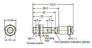
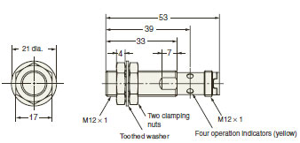
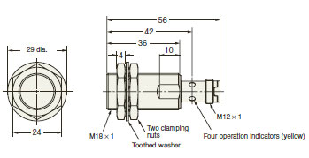
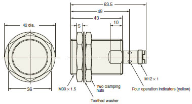
E2FM Proximity Sensor with All-stainless Housing/Dimensionslast update: March 1, 2017
(Unit: mm)
Tolerance class IT16 applies to dimensions in this data sheet unless otherwise specified.
Sensors
Pre-wired Models
E2FM-X1R5[]
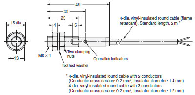
E2FM-X2[]
E2FM-X5[]
E2FM-X10[]
Pre-wired Connector Models
E2FM-X1R5D[]-M1TGJ-[]
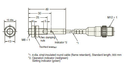
E2FM-X2D[]-M1TGJ-[]
E2FM-X5D[]-M1TGJ-[]
E2FM-X10D[]-M1TGJ-[]
M12 Connector Models
E2FM-X1R5[][]-M1
E2FM-X2[][]-M1
E2FM-X5[][]-M1
E2FM-X10[][]-M1
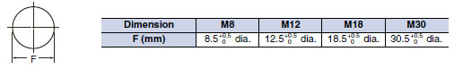
Mounting Hole Dimensions
last update: March 1, 2017
- NO. E2FM
- TYPE:Proximity Sensors Cylindrical
 Copyright Statement
 - DATE:2021-06-09
- Associated products:
E2EQ Spatter-resistant Proximity Sensor/Features E2EH Proximity Sensor Ideal for High Temperatures and Cleaning Processes/Features