OMRON ZW-8000 / 7000 / 5000 SeriesSensors/ Displacement Sensors / Measurement Sensors/High Precision Measurement Sensor
OMRON ZW-8000 / 7000 / 5000 Series Sensors
- ZW-8000 / 7000 / 5000 Series Confocal Fiber Displacement Sensor/Dimensions
- ZW-8000 / 7000 / 5000 Series Confocal Fiber Displacement Sensor/Lineup
- ZW-8000 / 7000 / 5000 Series Confocal Fiber Displacement Sensor/Catalog
- ZW-8000 / 7000 / 5000 Series Confocal Fiber Displacement Sensor/Specifications
- Purchase the OMRON ZW-8000 / 7000 / 5000 Series High Precision Measurement Sensor
OMRON ZW-8000 / 7000 / 5000 Series Dimensions
/Images/l_3500-25-258508-198x198.jpglast update: January 7, 2019
[Controller] Solutions for any in-line measurement application
For measurement of rattling or inclined "transparent objects or mirror surfaces"
Ultra-high-precision, high-speed type ZW-8000
High-precision in-line measurement of rattling or inclined shiny, thin, or minute parts


Mirror surfaces (inclined or curved surfaces)
Omron's, unique, white light confocal displacement sensor provides higher resolution measurements of angled or curved and shiny surfaces than traditional laser displacement sensors.

Transparent objects
The ZW-8000 Series can measure the top and bottom surfaces of a thin transparent sheet or film by separating the light reflected from both surfaces, which is difficult with conventional laser displacement sensors.


Minute objects
Thanks to its very small spot diameter, the ZW-8000 Series can measure targets on minute objects extremely precisely, which is impossible with a conventional laser displacement sensor with a large spot diameter.

A variety of sensor heads with a small spot diameter to suit your measurement conditions

*1. Typical value of the ZW-S8010/ZW-S7010/ZW-S5010 Sensor Heads.
*2. Typical value of the ZW-S8010 Sensor Heads when transparent objects with refractive index of 1.5 are measured.
*3. Typical value of the ZW-S8010 Sensor Heads
Note: The ZW-5000 standard type is available for measurements with standard precision and speed.
Measurement of “Coarse surfaces” moving at high speed
Ultra-high-speed, high-precision type ZW-7000
Ultra high-speed, stable measurement of diffuse reflective objects during movement


Shape
Using conventional sensors, the measurement accuracy can be achieved by increasing the averaging times, but downside is that this lowers the profile reproduction accuracy. The ZW-7000 acquires a sharp profile by sampling as fast as 20 μs without averaging, solving this issue.

Flatness of coarse surfaces *5
Our white light confocal displacement sensors can provide accurate flatness measurement by tracing an object once without being affected by its excessive reflection, the sensor head direction, nor the material hairline direction, which are difficult to track with a conventional laser displacement sensor.

*4. Please ask Omron sales representative for product data for other than the ZW-S7030.
*5. Objects with machining marks or hairline pattern
*6. ZW-S7020.
*7. Please ask Omron sales representative for product data for other than the ZW-S7020.
Note: All measurement graphs represent typical examples. Measurement may be affected by the shape or material of the object being measured.
Before final installation, test the sensor required for the application to validate that the desired measurements have been obtained.
[Sensor head] A wide sensor head offering for diverse integration requirements
New ultra-small sensor heads make integration more flexible
The continued evolution of products as they have become thinner, more curved, and more compact has meant that the inspection process has also become more diffcult, and this has necessitated visualization and assembly control in the upstream assembly process.
In response to this, Omron has developed a lineup including both square-shaped type sensor heads with long measurement distance, and ultra-small pen-shaped type (straight or right angle) sensor heads that can be installed in narrow spaces.
Ideal for assembly process
Reduce interference with stages, robots, or structures
Pen-shaped straight type
Measuring range
7±0.3 mm/10±0.7 mm
Linearity ±0.3 m
Weight*1 approx. 27 g
Note: Typical values

Pen-shaped right angle type
Measuring range
7±0.3 mm/10±0.7 mm
Linearity ±0.45 m
Weight*1 approx. 31 g
Note: Typical values

Ideal for inspection process
Perfect solution for strict inspection accuracy
Square-shaped straight type
Measuring range
10±0.5 mm/20±1 mm/30±2 mm/40±3 mm *2
Linearity ±0.3 m
Weight*1 approx. 170 g
Note: Typical values

*1. ZW-8000/ZW-7000 Series with 0.3 m fiber cable
*2. The 40 mm type is only available for the ZW-7000 Series.
[Usability] Reduce production cycle times through efficient arrangement and movements
Save Time and Money: No need to rotate the sensor
A conventional laser displacement sensor measures the height of an object based on the position of the spot on the receiver.
The machine requires an extra step to rotate the sensor according to the object shape or moving direction.
Our white light confocal displacement sensor can measure from the same installation position while moving in any direction, with no restriction on installation direction.

Flexible fiber cable for easy installation
The controller connects to the sensor head through a 3 mm diameter flexible fiber cable.
The cable has cleared a bending test consisting of 3,000,000 repetitions*2 for reliable application on moving parts.
*2. Omron's bending test condition: 3,000,000 bends to a 20 mm bending radius

Easy wiring for moving measurements
No preamplifiers or optical parts are used in the fiber cable, which makes it easy to route the cable through a cable carrier or protective conduit for moving measurements.

Extension cables for large machines
A 30-m extension fiber cable can be used to extend the distance to up to 32 m, supporting a flexible wiring in a large machine.

Compact fanless controller
The compact sensor controller, which integrates the optical unit including the light source and spectroscope, can be mounted on a DIN track, saving space in a control panel.
The fanless structure can be used in cleanrooms for manufacturing semiconductors and electronic components.

Increase throughput: Simultaneous measurements can be achieved using multiple sensor heads
Space restrictions prevent side-by-side installation of many traditional laser displacement sensors. The pen-shaped straight sensor heads can be installed close together to obtain multiple measurements at once, instead of measuring one at a time, thus reducing measurement time.

Further Benefits of White Light Confocal
No discrepancy in the measurement point
With a traditional laser displacement sensor, the measurement position and spot size vary with the height. This means there are times when the position cannot be measured with high resolution due to warping and inclination. With a white light confocal displacement sensor, the measurement point remains the same at any position in the measuring range so that precise measurements can always be made.

Measurement in narrow area and by the wall
When a traditional laser displacement sensor measures the inside of a narrow tube or the height of a small depression, the wall often obstructs the reflected light, and the orientation of the sensor and object must be adjusted many times. A white light confocal displacement sensor can measure the points in narrow spaces or small objects, without changing its installation orientation, because the emitted light and reflected light are positioned along the same axis.

[Usability] Reduce setup and tuning time
Reduced work - EMC measures and thermal design are not required
The sensor head contains no electronic parts and indicators that generate noise and heat.
The sensor head design maintains stable operation in installations with electronic or magnetic noise.
Devices in close proximity and measurement values are not affected by noise or heat from the sensor head.
EMC measures

Thermal design

[Patent pending] Multi-point scaling for stable measurements
The ZW Series measures up to 10 points to minimize measurement errors. *1
Even when the sensor head is installed at an angle or measures objects through glass, stable measurements can still be achieved, which is difficult with conventional 2-point scaling.

*1. Supported on ZW-8000 Series
No laser safety measures required
A white light source *2 eliminates the need for safety measures around the machine and safe use training for workers that are required for a laser light source.
Previously safety measures or laser were required
When a laser displacement sensor was used, a shield around the machine for safety was required and workers had to be trained for safe use.

*2. The ZW-8000 Series is categorized as Class 1
[Patented] Calibration ROM ensures compatibility and precision
The sensor controller is compatible with sensor heads, which enables quick replacement and saves costs. Each sensor head has its own calibration ROM that is used to load calibration values into the sensor controller, providing compatibility and high-precision measurements.

Stable measurement of multi-layer objects possible with advanced function “EdgeTracks” *2 [Patent pending]
When measuring objects with multiple layers, the white light confocal displacement sensor can stably measure target edges even if the object rattles and certain of the edges cannot be measured.

last update: January 7, 2019
Purchase the OMRON High Precision Measurement Sensor Please fill in the following
If you have just landed here, this product OMRON ZW-8000 / 7000 / 5000 Series Sensors,Sensors is offered online by Tianin FLD Technical Co.,Ltd. This is an online store providing Sensors at wholesale prices for consumers. You can call us or send enquiry, we would give you the prices, packing,deliverty and more detailed information on the ZW-8000 / 7000 / 5000 Series We cooperate with DHL,TNT,FEDEX,UPS,EMS,etc.They guarantee to meet your needs in terms of time and money,even if you need your OMRON ZW-8000 / 7000 / 5000 SeriesSensors tomorrow morning (aka overnight or next day air) on your desk, 2, 3 days or more.Note to international customers, YES, we ship worldwide.
E3X-DA-S / MDA Digital Fiber Amplifier Unit/Features
D40A / G9SX-NS Compact Non-Contact Door Switch/Non-Contact Door Switch Controller/Features
E5EC-T Programmable Temperature Controller (Digital Controller) (48 × 96 mm)/Features
H3CR-F Solid-state Timer/Features
ZS-CRT Sensor Communications Unit/Features
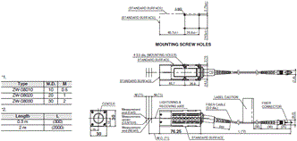
OMRON ZW-8000 / 7000 / 5000 Series dimension
ZW-8000 / 7000 / 5000 Series Confocal Fiber Displacement Sensor/Dimensionslast update: June 12, 2018
(Unit: mm)
Sensor Head
Square-shaped straight type
ZW-S8010 []M/S8020 []M/S8030 []M
Pen-shaped straight type
ZW-SP8007 []M
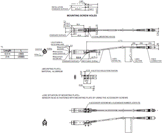
ZW-SP8010 []M
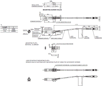
Pen-shaped right angle type
ZW-SPR8007 []M
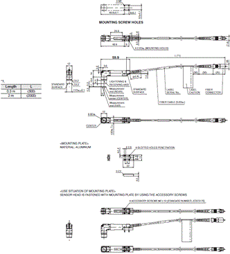
ZW-SPR8010 []M
Square-shaped straight type
ZW-S7010 []M/S7020 []M/S7030 []M/S7040 []M
Pen-shaped straight type
ZW-SP7007 []M
ZW-SP7010 []M
Pen-shaped right angle type
ZW-SPR7007 []M
ZW-SPR7010 []M
Square-shaped straight type
ZW-S5010 []M/S5020 []M/S5030 []M
Pen-shaped straight type
ZW-SP5007 []M
ZW-SP5010 []M
Pen-shaped right angle type
ZW-SPR5007 []M
ZW-SPR5010 []M
Sensor Controller
ZW-8000T
ZW-7000T
ZW-5000T
Extension Fiber Cable
ZW-XF8002R/XF8005R/XF8010R/XF8020R/XF8030R
ZW-XF7002R/XF7005R/XF7010R/XF7020R/XF7030R
ZW-XF5002R/XF5005R/XF5010R/XF5020R/XF5030R

last update: June 12, 2018
OMRON ZW-8000 / 7000 / 5000 Series lineup
ZW-8000 / 7000 / 5000 Series Confocal Fiber Displacement Sensor/Lineuplast update: December 20, 2018
ZW-8000
Sensor Head
Square-shaped straight type
| Appearance | Measuring range | Spot diameter | Static resolution * | Cable length | Model |
|---|---|---|---|---|---|
 |  | 4 μm dia. | 0.25 μm | 2 m | ZW-S8010 2M |
| 0.3 m | ZW-S8010 0.3M | ||||
 | 7 μm dia. | 0.25 μm | 2 m | ZW-S8020 2M | |
| 0.3 m | ZW-S8020 0.3M | ||||
 | 10 μm dia. | 0.25 μm | 2 m | ZW-S8030 2M | |
| 0.3 m | ZW-S8030 0.3M |
* Values when the Sensor Controller ZW-8000T is used.
Pen-shaped straight type
| Appearance | Measuring range | Spot diameter | Static resolution * | Cable length | Model |
|---|---|---|---|---|---|
 |  | 7 μm dia. | 0.25 μm | 2 m | ZW-SP8007 2M |
| 0.3 m | ZW-SP8007 0.3M | ||||
 | 10 μm dia. | 0.25 μm | 2 m | ZW-SP8010 2M | |
| 0.3 m | ZW-SP8010 0.3M |
* Values when the Sensor Controller ZW-8000T is used.
Pen-shaped right angle type
| Appearance | Measuring range | Spot diameter | Static resolution * | Cable length | Model |
|---|---|---|---|---|---|
 |  | 8 μm dia. | 0.25 μm | 2 m | ZW-SPR8007 2M |
| 0.3 m | ZW-SPR8007 0.3M | ||||
 | 11 μm dia. | 0.25 μm | 2 m | ZW-SPR8010 2M | |
| 0.3 m | ZW-SPR8010 0.3M |
* Values when the Sensor Controller ZW-8000T is used.
Sensor Controller with EtherCAT
| Appearance | Power supply | Output type | Model |
|---|---|---|---|
 | 24 VDC | NPN/PNP | ZW-8000T |
Cable
| Appearance | Item | Cable length | Model |
|---|---|---|---|
 | Extension Fiber Cable (from Sensor Head to Sensor Controller), (Fiber Adapter ZW-XFCS is included) | 2 m | ZW-XF8002R |
| 5 m | ZW-XF8005R | ||
| 10 m | ZW-XF8010R | ||
| 20 m | ZW-XF8020R | ||
| 30 m | ZW-XF8030R | ||
 | Fiber Adapter (used between Sensor Head pre-wired cable and Extension Fiber Cable) | ⎯ | ZW-XFCS |
Note: Extension Fiber Cable ZW-XF80[][]R can be used with the firmware version 3.000 or later. If you have an old version
Sensor Controller, register as a Sysmac member and download the latest firmware and tools to update your Sensor
Controller. Refer to the Sysmac member registration sheet that is enclosed with the Sensor Controller for details on
member registration and firmware download.
ZW-7000
Sensor Head
Square-shaped straight type
| Appearance | Measuring range | Spot diameter | Static resolution * | Cable length | Model |
|---|---|---|---|---|---|
 |  | 50 μm dia. | 0.25 μm | 2 m | ZW-S7010 2M |
| 0.3 m | ZW-S7010 0.3M | ||||
 | 70 μm dia. | 0.25 μm | 2 m | ZW-S7020 2M | |
| 0.3 m | ZW-S7020 0.3M | ||||
 | 100 μm dia. | 0.25 μm | 2 m | ZW-S7030 2M | |
| 0.3 m | ZW-S7030 0.3M | ||||
 | 120 μm dia. | 0.25 μm | 2m | ZW-S7040 2M | |
| 0.3m | ZW-S7040 0.3M |
* Values when the Sensor Controller ZW-7000T is used.
Pen-shaped straight type
| Appearance | Measuring range | Spot diameter | Static resolution * | Cable length | Model |
|---|---|---|---|---|---|
 |  | 130 μm dia. | 0.25 μm | 2 m | ZW-SP7007 2M |
| 0.3 m | ZW-SP7007 0.3M | ||||
 | 170 μm dia. | 0.25 μm | 2 m | ZW-SP7010 2M | |
| 0.3 m | ZW-SP7010 0.3M |
* Values when the Sensor Controller ZW-7000T is used.
Pen-shaped right angle type
| Appearance | Measuring range | Spot diameter | Static resolution * | Cable length | Model |
|---|---|---|---|---|---|
 |  | 150 μm dia. | 0.25 μm | 2 m | ZW-SPR7007 2M |
| 0.3 m | ZW-SPR7007 0.3M | ||||
 | 190 μm dia. | 0.25 μm | 2 m | ZW-SPR7010 2M | |
| 0.3 m | ZW-SPR7010 0.3M |
* Values when the Sensor Controller ZW-7000T is used.
Sensor Controller with EtherCAT
| Appearance | Power supply | Output type | Model |
|---|---|---|---|
 | 24 VDC | NPN/PNP | ZW-7000T |
Cable
| Appearance | Item | Cable length | Model |
|---|---|---|---|
 | Extension Fiber Cable (from Sensor Head to Sensor Controller), (Fiber Adapter ZW-XFCM is included) | 2 m | ZW-XF7002R |
| 5 m | ZW-XF7005R | ||
| 10 m | ZW-XF7010R | ||
| 20 m | ZW-XF7020R | ||
| 30 m | ZW-XF7030R | ||
 | Fiber Adapter (used between Sensor Head pre-wired cable and Extension Fiber Cable) | ⎯ | ZW-XFCM |
Note: Cables of 10, 20, and 30 m can be used with the firmware version 2.100 or later. If you have an old version Sensor
Controller, register as a Sysmac member and download the latest firmware and tools to update your Sensor
Controller. Refer to the Sysmac member registration sheet that is enclosed with the Sensor Controller for details on
member registration and firmware download.
ZW-5000
Sensor Head
Square-shaped straight type
| Appearance | Measuring range | Spot diameter | Static resolution * | Cable length | Model |
|---|---|---|---|---|---|
 |  | 9 μm dia. | 0.25 μm | 2 m | ZW-S5010 2M |
| 0.3 m | ZW-S5010 0.3M | ||||
 | 13 μm dia. | 0.25 μm | 2 m | ZW-S5020 2M | |
| 0.3 m | ZW-S5020 0.3M | ||||
 | 18 μm dia. | 0.25 μm | 2 m | ZW-S5030 2M | |
| 0.3 m | ZW-S5030 0.3M |
* Values when the Sensor Controller ZW-5000T is used.
Pen-shaped straight type
| Appearance | Measuring range | Spot diameter | Static resolution * | Cable length | Model |
|---|---|---|---|---|---|
 |  | 13 μm dia. | 0.25 μm | 2 m | ZW-SP5007 2M |
| 0.3 m | ZW-SP5007 0.3M | ||||
 | 18 μm dia. | 0.25 μm | 2 m | ZW-SP5010 2M | |
| 0.3 m | ZW-SP5010 0.3M |
* Values when the Sensor Controller ZW-5000T is used.
Pen-shaped right angle type
| Appearance | Measuring range | Spot diameter | Static resolution * | Cable length | Model |
|---|---|---|---|---|---|
 |  | 15 μm dia. | 0.25 μm | 2 m | ZW-SPR5007 2M |
| 0.3 m | ZW-SPR5007 0.3M | ||||
 | 20 μm dia. | 0.25 μm | 2 m | ZW-SPR5010 2M | |
| 0.3 m | ZW-SPR5010 0.3M |
* Values when the Sensor Controller ZW-5000T is used.
Sensor Controller with EtherCAT
| Appearance | Power supply | Output type | Model |
|---|---|---|---|
 | 24 VDC | NPN/PNP | ZW-5000T |
Cable
| Appearance | Item | Cable length | Model |
|---|---|---|---|
 | Extension Fiber Cable (from Sensor Head to Sensor Controller), (Fiber Adapter ZW-XFC2 is included) | 2 m | ZW-XF5002R |
| 5 m | ZW-XF5005R | ||
| 10 m | ZW-XF5010R | ||
| 20 m | ZW-XF5020R | ||
| 30 m | ZW-XF5030R | ||
 | Fiber Adapter (used between Sensor Head pre-wired cable and Extension Fiber Cable) | ⎯ | ZW-XFC2 |
Note: Extension Fiber Cable ZW-XF50[][]R can be used with the firmware version 2.100 or later. If you have an old version
Sensor Controller, register as a Sysmac member and download the latest firmware and tools to update your Sensor
Controller. Refer to the Sysmac member registration sheet that is enclosed with the Sensor Controller for details on
member registration and firmware download.
Common cables
| Appearance | Item | Cable length | Model |
|---|---|---|---|
 | Parallel caable for ZW-8000T/7000T/5000T 32-pole (included with Sensor Controller ZW-8000T/7000T/5000T) | 2 m | ZW-XCP2E |
 | RS-232C Cable for personal computer | 2 m | ZW-XRS2 |
 | RS-232C Cable for PLC/programmable terminal | 2 m | ZW-XPT2 |
Recommended EtherCAT Communications Cables
Use Straight STP (shielded twisted-pair) cable of category 5 or higher with double shielding (braiding and aluminum foil tape) for EtherCAT.
Cable with Connectors
| Item | Appearance | Recommended manufacturer | Cable length (m) *1 | Model |
|---|---|---|---|---|
| Standard type Cable with Connectors on Both Ends (RJ45/RJ45) Wire Gauge and Number of Pairs: AWG26, 4-pair Cable Cable Sheath material: LSZH *2 Cable color: Yellow *3 |  | OMRON | 0.3 | XS6W-6LSZH8SS30CM-Y |
| 0.5 | XS6W-6LSZH8SS50CM-Y | |||
| 1 | XS6W-6LSZH8SS100CM-Y | |||
| 2 | XS6W-6LSZH8SS200CM-Y | |||
| 3 | XS6W-6LSZH8SS300CM-Y | |||
| 5 | XS6W-6LSZH8SS500CM-Y | |||
| Rugged type Cable with Connectors on Both Ends (RJ45/RJ45) Wire Gauge and Number of Pairs: AWG22, 2-pair Cable |  | OMRON | 0.3 | XS5W-T421-AMD-K |
| 0.5 | XS5W-T421-BMD-K | |||
| 1 | XS5W-T421-CMD-K | |||
| 2 | XS5W-T421-DMD-K | |||
| 5 | XS5W-T421-GMD-K | |||
| 10 | XS5W-T421-JMD-K | |||
| Rugged type Cable with Connectors on Both Ends (M12 Straight/RJ45) Wire Gauge and Number of Pairs: AWG22, 2-pair Cable |  | OMRON | 0.3 | XS5W-T421-AMC-K |
| 0.5 | XS5W-T421-BMC-K | |||
| 1 | XS5W-T421-CMC-K | |||
| 2 | XS5W-T421-DMC-K | |||
| 5 | XS5W-T421-GMC-K | |||
| 10 | XS5W-T421-JMC-K | |||
| Rugged type Cable with Connectors on Both Ends (M12 Right-angle/RJ45) Wire Gauge and Number of Pairs: AWG22, 2-pair Cable |  | OMRON | 0.3 | XS5W-T422-AMC-K |
| 0.5 | XS5W-T422-BMC-K | |||
| 1 | XS5W-T422-CMC-K | |||
| 2 | XS5W-T422-DMC-K | |||
| 5 | XS5W-T422-GMC-K | |||
| 10 | XS5W-T422-JMC-K |
Note: For details, refer to Cat.No.G019.
*1. Standard type cables length 0.2, 0.3, 0.5, 1, 1.5, 2, 3, 5, 7.5, 10, 15 and 20m are available.
Rugged type cables length 0.3, 0.5, 1, 2, 3, 5, 10 and 15m are available.
*2. The lineup features Low Smoke Zero Halogen cables for in-cabinet use and PUR cables for out-of-cabinet use.
*3. Cables colors are available in blue, yellow, or Green
Cables / Connectors
Wire Gauge and Number of Pairs: AWG24, 4-pair Cable
| Item | Appearance | Recommended manufacturer | Model |
|---|---|---|---|
| Cables | ⎯ | Hitachi Metals, Ltd. | NETSTAR-C5E SAB 0.5 × 4P CP * |
| ⎯ | Kuramo Electric Co. | KETH-SB * | |
| ⎯ | SWCC Showa Cable Systems Co. | FAE-5004 * | |
| RJ45 Connectors | ⎯ | Panduit Corporation | MPS588-C * |
* We recommend to use above cable and connector together.
Wire Gauge and Number of Pairs: AWG22, 2-pair Cable
| Item | Appearance | Recommended manufacturer | Model |
|---|---|---|---|
| Cables | ⎯ | Kuramo Electric Co. | KETH-PSB-OMR * |
| ⎯ | JMACS Japan Co.,Ltd. | PNET/B * | |
| RJ45 Assembly Connector |  | OMRON | XS6G-T421-1 * |
Note: Connect both ends of cable shielded wires to the connector hoods.
* We recommend to use above cable and connector together.
Industrial switching hubs for Ethernet
| Appearance | Number of ports | Failure detection | Current consumption | Model |
|---|---|---|---|---|
 | 3 | None | 0.22A | W4S1-03B |
 | 5 | None | 0.22A | W4S1-05B |
| Supported | W4S1-05C |
Note: Industrial switching hubs are cannot be used for EtherCAT.
EtherCAT junction slaves
| Appearance | Number of ports | Power supply voltage | Current consumption | Model |
|---|---|---|---|---|
 | 3 | 20.4 to 28.8 VDC (24 VDC -15 to 20%) | 0.08A | GX-JC03 |
 | 6 | 0.17A | GX-JC06 |
Note: 1. Please do not connect EtherCAT junction slave with OMRON position control unit, Model CJ1W-NC[]81/[]82.
2. EtherCAT junction slaves cannot be used for EtherNet/IP™ and Ethernet.
Automation Software Sysmac Studio
Please purchase a DVD and required number of licenses the first time you purchase the Sysmac Studio. DVDs and licenses are available individually.
Each model of licenses does not include DVD.
| Item | Specifications | Model | Stand- ards | ||
|---|---|---|---|---|---|
| Number of licenses | Media | ||||
| Sysmac Studio Standard Edition Ver.1[][] *2 | The Sysmac Studio is the software that provides an integrated environment for setting, programming, debugging and maintenance of machine automation controllers including the NJ/NX-series CPU Units, NY-series Industrial PC, EtherCat Slave, and the HMI. Sysmac Studio runs on the following OS. Windows 7 (32-bit/64-bit version)/Windows 8 (32-bit/64-bit version)/Windows 8.1 (32-bit/ 64-bit version)/Windows 10 (32-bit/64-bit version) This software provides functions of the Measurement Sensor Edition. Refer to your OMRON website for details. | ⎯ (Media only) | DVD | SYSMAC-SE200D | ⎯ |
| 1 license*1 | ⎯ | SYSMAC-SE201L | ⎯ | ||
| Sysmac Studio Measurement Sensor Edition Ver.1.[][] | Sysmac Studio Measurement Sensor Edition is a limited license that provides selected functions required for ZW-series Displacement Sensor settings. Because this product is a license only, you need the Sysmac Standard Edition DVD media to install it. | 1 license | ⎯ | SYSMAC-ME001L | ⎯ |
| 3 license | ⎯ | SYSMAC-ME003L | ⎯ | ||
*1. Multiple licenses are available for the Sysmac Studio (3, 10, 30, or 50 licenses).
*2. ZW-8000/7000/5000 is supported by Sysmac Studio version 1.22 or higher.
Fiber Cleaner
| Item | Recommended manufacturer | Model | Applicable Model | Contacts | ||
|---|---|---|---|---|---|---|
| ZW-8000 | ZW-7000 | ZW-5000 | ||||
| Fiber Connector Cleaner *1 | OMRON | ZW-XCL | Yes | Yes | Yes | OMRON |
| NEOCLEAN-M | NTT Advanced Technology Corporation | ATC-NE-M1 | No | Yes | No | *2 |
| OPTIPOP R1 | ATC-RE-01 | Yes (Sensor Head only) | No | Yes (Sensor Head only) | ||
*1. Place orders in units of boxes (contacting 10 units).
*2. Contacts
[Request for an Estimate]
http://www.ntt-at.com/product/optical_cleaner/Distributors.html
[Request for Information]
NTT Advanced Technology Corporation
Muza Kawasaki Central Tower, 1310 Omiya-cho Saiwai-ku, Kawasaki-shi, Kanagawa, 212-0014, Japan
TEL: +81 44 589 5894
http://www.ntt-at.com/product/optical_cleaner/
last update: December 20, 2018
OMRON ZW-8000 / 7000 / 5000 Series catalog
ZW-8000 / 7000 / 5000 Series Confocal Fiber Displacement Sensor/Catalog- Catalog
- Manual
- CAD
English
Global Edition
| Catalog Name | Catalog Number [size] | Last Update | |
|---|---|---|---|
| | Q250-E1-04 [15620KB] | Jan 07, 201920190107 | ZW-8000/7000/5000 Series Catalog |
OMRON ZW-8000 / 7000 / 5000 Series specification
ZW-8000 / 7000 / 5000 Series Confocal Fiber Displacement Sensor/Specificationslast update: June 12, 2018
Sensor Head
ZW-S8010/S8020/S8030/SP8007/SP8010/SPR8007/SPR8010
| Item | Specifications | ||
|---|---|---|---|
| ZW-S8010 | ZW-S8020 | ZW-S8030 | |
| Sensor controller | ZW-8000T | ||
| Sensor head type | Square-shaped straight type | ||
| Measurement center distance *1 | 10 mm | 20 mm | 30 mm |
| Measuring range *2 | ±0.5 mm | ±1mm | ±2mm |
| Static resolution *3 | 0.25 μm | ||
| Linearity *4 | ±0.3 μm | ±0.6 μm | ±1.3 μm |
| Spot diameter (Total measurent range) *5 | 4 μm dia. | 7 μm dia. | 10 μm dia. |
| Measurement cycle *6 | 60 μs to 7,500 μs | ||
| Operating ambient illumination | Illumination on object surface max.30000 Lx: (incandescent light) | ||
| Ambient temperature range | Operation: 0 to 50°C, Storage: -15 to +60°C (No freezing and condensation) | ||
| Ambient humidity range | Operation/storage: 35 or 85%RH (No condensation) | ||
| Degree of protection | IP40 (IEC60529) | ||
| Vibration resistance (destructive) | 10 to 150 Hz (half amplitude 0.35 mm), 80 mins in each of X/Y/Z directions | ||
| Shock resistance (destructive) | 150 m/s2, 6 direction, 3 times each (up/down, left/right, forward/backward) | ||
| Temperature characteristic *7 | 0.6 μm/°C (0.2 μm/°C) | 1.1 μm/°C (0.5 μm/°C) | 1.8 μm/°C (1.0 μm/°C) |
| LED Safety | Risk Group 3 (IEC62471) | ||
| Material | Chassis: aluminum die cast Fiber cable sheath: PVC Calibration ROM: PC | ||
| Fiber cable length | 0.3 m, 2 m (flex-resistant cable) | ||
| Fiber cable minimum bend radius | 20 mm | ||
| Insulation resistance (Calibration ROM) | Between case and all terminals: 20 MΩ (by 250 VDC) | ||
| Dielectric strength (Calibration ROM) | Between case and all terminals: 1000 VAC, 50/60 Hz, 1 min | ||
| Weight | Fiber cable length 0.3m Approx. 170g Fiber cable length 2m Approx. 180g | ||
| Accessories | Calibration ROM fixing screw (M2×5mm) × 1, Fiber cable protective cap × 1, Strap × 1, Instruction Manual, Precautions | ||
| Item | Specifications | |||
|---|---|---|---|---|
| ZW-SP8007 | ZW-SP8010 | ZW-SPR8007 | ZW-SPR8010 | |
| Sensor controller | ZW-8000T | |||
| Sensor head type | Pen-shaped straight type | Pen-shaped right angle type | ||
| Measurement center distance *1 | 7 mm | 10 mm | 7 mm | 10 mm |
| Measuring range *2 | ±0.3 mm | ±0.7 mm | ±0.3 mm | ±0.7 mm |
| Static resolution *3 | 0.25 μm | |||
| Linearity *4 | ±0.3 μm | ±0.45 μm | ±0.45 μm | ±0.7 μm |
| Spot diameter (Total measurent range) *5 | 7 μm dia. | 10 μm dia. | 8 μm dia. | 11 μm dia. |
| Measurement cycle *6 | 60 μs to 7,500 μs | |||
| Operating ambient illumination | Illumination on object surface max.30000 Lx: (incandescent light) | |||
| Ambient temperature range | Operation: 0 to 50°C, Storage: -15 to +60°C (No freezing and condensation) | |||
| Ambient humidity range | Operation/storage: 35 or 85%RH (No condensation) | |||
| Degree of protection | IP40 (IEC60529) | |||
| Vibration resistance (destructive) | 10 to 150 Hz (half amplitude 0.35 mm), 80 mins in each of X/Y/Z directions | |||
| Shock resistance (destructive) | 150 m/s2, 6 direction, 3 times each (up/down, left/right, forward/backward) | |||
| Temperature characteristic *7 | 0.8 μm/°C (0.4 mm/°C) | 0.8 μm/°C (0.4 mm/°C) | 0.8 μm/°C (0.4 mm/°C) | 0.8 μm/°C (0.4 mm/°C) |
| LED Safety | Risk Group 3 (IEC62471) | |||
| Material | Chassis: SUS Fiber cable sheath: PVC Calibration ROM: PC Mounting Plate: Aluminum | Chassis: SUS, aluminum Fiber cable sheath: PVC Calibration ROM: PC Mounting Plate: Aluminum | ||
| Fiber cable length | 0.3 m, 2 m (flex-resistant cable) | |||
| Fiber cable minimum bend radius | 20 mm | |||
| Insulation resistance (Calibration ROM) | Between case and all terminals: 20 MΩ (by 250 VDC) | |||
| Dielectric strength (Calibration ROM) | Between case and all terminals: 1000 VAC, 50/60 Hz, 1 min | |||
| Weight | Fiber cable length 0.3m Approx. 27 g Fiber cable length 2m Approx. 37 g | Fiber cable length 0.3m Approx. 31 g Fiber cable length 2m Approx. 41 g | ||
| Accessories | Installation plate × 1, Unit fixing screws (M2 × 10 mm) × 4, Calibration ROM fixing screw (M2 × 5 mm) × 1, Fiber cable protective cap × 1, Strap × 1, Instruction Manual, Precautions | |||
*1. Indicates the distance from the front of the sensor head. The pen-shaped right angle type has a maximum individual
difference of ±0.15 mm in the distance from the front of the sensor head.
*2. The measurement range is higher 100 μs than measurement cycle.
*3. Capacity value when OMRON standard mirror surface target is measured at the measurement center distance as the
average of 16,384 times.
The value when the Sensor Controller ZW-8000T is connected.
*4. Material setting for the OMRON standard mirror surface target: Error from an ideal straight line when measuring on
mirror surface.
*5. Capacity value defined by 1/e2 (13.5%) of the peak optical intensity of the measurement wavelength.
*6. When an extension fiber cable of 2 m or longer is connected, the setting rage of the measurement cycle (exposure
time) changes. For details, refer to Setting Measurement Cycle in the ZW-8000/7000/5000 User's Manual (Cat. No.
Z362).
*7. Actual value of the change in measurement value at the measurement center distance when fastened with an
aluminum jig between the Sensor Head and the target, and with the Sensor Head and the Sensor Controller set in the
same temperature environment.
The value in parentheses is the actual value when using an SUS304 jig.
When measuring the thickness, the value is calculated from the difference between the heights of the surface and rear
surface, so there is no effect on the temperature change.
ZW-S7010/S7020/S7030/S7040/SP7007/SP7010/SPR7007/SPR7010
| Item | Specifications | |||
|---|---|---|---|---|
| ZW-S7010 | ZW-S7020 | ZW-S7030 | ZW-S7040 | |
| Sensor controller | ZW-7000T | |||
| Sensor head type | Square-shaped straight type | |||
| Measurement center distance *1 | 10 mm | 20 mm | 30 mm | 40 mm |
| Measuring range *2 | ±0.5 mm | ±1 mm | ±2 mm | ±3 mm |
| Static resolution *3 | 0.25 μm | |||
| Linearity *4 | ±0.45 μm | ±0.9 μm | ±2.0 μm | ±3.0 μm |
| Spot diameter (Total measurent range) *5 | 50 μm dia. | 70 μm dia. | 100 μm dia. | 120 μm dia. |
| Measurement cycle *6 | 20 μs to 400 μs | |||
| Operating ambient illumination | Illumination on object surface max.30000 Lx: (incandescent light) | |||
| Ambient temperature range | Operation: 0 to 50°C, Storage: -15 to +60°C (No freezing and condensation) | |||
| Ambient humidity range | Operation/storage: 35 or 85%RH (No condensation) | |||
| Degree of protection | IP40 (IEC60529) | |||
| Vibration resistance (destructive) | 10 to 150 Hz (half amplitude 0.35 mm), 80 mins in each of X/Y/Z directions | |||
| Shock resistance (destructive) | 150 m/s2, 6 direction, 3 times each (up/down, left/right, forward/backward) | |||
| Temperature characteristic *7 | 0.6 μm/°C (0.2 μm/°C) | 1.1 μm/°C (0.5 μm/°C) | 1.8 μm/°C (1.0 μm/°C) | 2.1 μm/°C (1.2 μm/°C) |
| LED Safety | Risk Group 3 (IEC62471) | |||
| Material | Chassis: aluminum die cast Fiber cable sheath: PVC Calibration ROM: PC | |||
| Fiber cable length | 0.3 m, 2 m (flex-resistant cable) | |||
| Fiber cable minimum bend radius | 20 mm | |||
| Insulation resistance (Calibration ROM) | Between case and all terminals: 20 MΩ (by 250 VDC) | |||
| Dielectric strength (Calibration ROM) | Between case and all terminals: 1000 VAC, 50/60 Hz, 1 min | |||
| Weight | Fiber cable length 0.3 m Approx. 170g Fiber cable length 2 m Approx. 180g | |||
| Accessories | Calibration ROM fixing screw (M2×5mm) × 1, Fiber cable protective cap × 1, Strap × 2, Instruction Manual, Precautions | |||
| Item | Specifications | |||
|---|---|---|---|---|
| ZW-SP7007 | ZW-SP7010 | ZW-SPR7007 | ZW-SPR7010 | |
| Sensor controller | ZW-7000T | |||
| Sensor head type | Pen-shaped straight type | Pen-shaped right angle type | ||
| Measurement center distance *1 | 7 mm | 10 mm | 7 mm | 10 mm |
| Measuring range *2 | ±0.3 mm | ±0.7 mm | ±0.3 mm | ±0.7 mm |
| Static resolution *3 | 0.25 μm | |||
| Linearity *4 | ±0.45 μm | ±0.7 μm | ±0.7 μm | ±1.1 μm |
| Spot diameter (Total measurent range) *5 | 130 μm dia. | 170 μm dia. | 150 μm dia. | 190 μm dia. |
| Measurement cycle *6 | 20 μs to 400 μs | |||
| Operating ambient illumination | Illumination on object surface max.30000 Lx: (incandescent light) | |||
| Ambient temperature range | Operation: 0 to 50°C, Storage: -15 to +60°C (No freezing and condensation) | |||
| Ambient humidity range | Operation/storage: 35 or 85%RH (No condensation) | |||
| Degree of protection | IP40 (IEC60529) | |||
| Vibration resistance (destructive) | 10 to 150 Hz (half amplitude 0.35 mm), 80 mins in each of X/Y/Z directions | |||
| Shock resistance (destructive) | 150 m/s2, 6 direction, 3 times each (up/down, left/right, forward/backward) | |||
| Temperature characteristic *7 | 0.8 μm/°C (0.4 μm/°C) | 0.8 μm/°C (0.4 μm/°C) | 0.8 μm/°C (0.4 μm/°C) | 0.8 μm/°C (0.4 μm/°C) |
| LED Safety | Risk Group 3 (IEC62471) | |||
| Material | Chassis: SUS Fiber cable sheath: PVC Calibration ROM: PC Mounting Plate: Aluminum | Chassis: SUS, aluminum Fiber cable sheath: PVC Calibration ROM: PC Mounting Plate: Aluminum | ||
| Fiber cable length | 0.3 m, 2 m (flex-resistant cable) | |||
| Fiber cable minimum bend radius | 20 mm | |||
| Insulation resistance (Calibration ROM) | Between case and all terminals: 20 MΩ (by 250 VDC) | |||
| Dielectric strength (Calibration ROM) | Between case and all terminals: 1000 VAC, 50/60 Hz, 1 min | |||
| Weight | Fiber cable length 0.3 m Approx. 27 g Fiber cable length 2 m Approx. 37 g | Fiber cable length 0.3 m Approx. 31 g Fiber cable length 2 m Approx. 41 g | ||
| Accessories | Installation plate × 1, Unit fixing screws (M2 × 10 mm) × 4, Calibration ROM fixing screw (M2 × 5 mm) × 1, Fiber cable protective cap × 1, Strap × 2, Instruction Manual, Precautions | |||
*1. Indicates the distance from the front of the sensor head. The pen-shaped right angle type has a maximum individual
difference of ±0.15 mm in the distance from the front of the sensor head.
*2. The measurement range is higher 28 μs than measurement cycle.
*3. Capacity value when OMRON standard mirror surface target is measured at the measurement center distance as the
average of 16,384 times.
The value when the Sensor Controller ZW-7000T is connected.
*4. Material setting for the OMRON standard mirror surface target: Error from an ideal straight line when measuring on
mirror surface.
*5. Capacity value defined by 1/e2 (13.5%) of the peak optical intensity of the measurement wavelength.
*6. When an extension fiber cable of 10 m or longer is connected, the setting rage of the measurement cycle (exposure
time) changes. For details, refer to Setting Measurement Cycle in the ZW-8000/7000/5000 User's Manual (Cat. No.
Z362).
*7. Actual value of the change in measurement value at the measurement center distance when fastened with an
aluminum jig between the Sensor Head and the target, and with the Sensor Head and the Sensor Controller set in the
same temperature environment.
The value in parentheses is the actual value when using an SUS304 jig.
When measuring the thickness, the value is calculated from the difference between the heights of the surface and rear
surface, so there is no effect on the temperature change.
ZW-S5010/S5020/S5030/SP5007/SP5010/SPR5007/SPR5010
| Item | Specifications | ||
|---|---|---|---|
| ZW-S5010 | ZW-S5020 | ZW-S5030 | |
| Sensor controller | ZW-5000T | ||
| Sensor head type | Square-shaped straight type | ||
| Measurement center distance *1 | 10 mm | 20 mm | 30 mm |
| Measuring range | ±0.5 mm | ±1 mm | ±2 mm |
| Static resolution *2 | 0.25 μm | ||
| Linearity *3 | ±0.45 μm | ±0.9 μm | ±2.0 μm |
| Spot diameter (Total measurent range) *4 | 9 μm dia. | 13 μm dia. | 18 μm dia. |
| Measurement cycle *5 | 80 μs to 1,600 μs | ||
| Operating ambient illumination | Illumination on object surface max.30000 Lx: (incandescent light) | ||
| Ambient temperature range | Operation: 0 to 50°C, Storage: -15 to +60°C (No freezing and condensation) | ||
| Ambient humidity range | Operation/storage: 35 or 85%RH (No condensation) | ||
| Degree of protection | IP40 (IEC60529) | ||
| Vibration resistance (destructive) | 10 to 150 Hz (half amplitude 0.35 mm), 80 mins in each of X/Y/Z directions | ||
| Shock resistance (destructive) | 150 m/s2, 6 direction, 3 times each (up/down, left/right, forward/backward) | ||
| Temperature characteristic *6 | 0.6 μm/°C (0.2 μm/°C) | 1.1 μm/°C (0.5 μm/°C) | 1.8 μm/°C (1.0 μm/°C) |
| LED Safety | Risk Group 3 (IEC62471) | ||
| Material | Chassis: aluminum die cast Fiber cable sheath: PVC Calibration ROM: PC | ||
| Fiber cable length | 0.3 m, 2 m (flex-resistant cable) | ||
| Fiber cable minimum bend radius | 20 mm | ||
| Insulation resistance (Calibration ROM) | Between case and all terminals: 20 MΩ (by 250 VDC) | ||
| Dielectric strength (Calibration ROM) | Between case and all terminals: 1000 VAC, 50/60 Hz, 1 min | ||
| Weight | Fiber cable length 0.3m Approx. 170g Fiber cable length 2m Approx. 180g | ||
| Accessories | Calibration ROM fixing screw (M2×5mm) × 1, Fiber cable protective cap × 1, Strap × 1, Instruction Manual, Precautions | ||
| Item | Specifications | |||
|---|---|---|---|---|
| ZW-SP5007 | ZW-SP5010 | ZW-SPR5007 | ZW-SPR5010 | |
| Sensor controller | ZW-5000T | |||
| Sensor head type | Pen-shaped straight type | Pen-shaped right angle type | ||
| Measurement center distance *1 | 7 mm | 10 mm | 7 mm | 10 mm |
| Measuring range | ±0.3 mm | ±0.7 mm | ±0.3 mm | ±0.7 mm |
| Static resolution *2 | 0.25 μm | |||
| Linearity *3 | ±0.45 μm | ±0.7 μm | ±0.7 μm | ±1.1 μm |
| Spot diameter (Total measurent range) *4 | 13 μm dia. | 18 μm dia. | 15 μm dia. | 20 μm dia. |
| Measurement cycle *5 | 80 μs to 1,600 μs | |||
| Operating ambient illumination | Illumination on object surface max.30000 Lx: (incandescent light) | |||
| Ambient temperature range | Operation: 0 to 50°C, Storage: -15 to +60°C (No freezing and condensation) | |||
| Ambient humidity range | Operation/storage: 35 or 85%RH (No condensation) | |||
| Degree of protection | IP40 (IEC60529) | |||
| Vibration resistance (destructive) | 10 to 150 Hz (half amplitude 0.35 mm), 80 mins in each of X/Y/Z directions | |||
| Shock resistance (destructive) | 150 m/s2, 6 direction, 3 times each (up/down, left/right, forward/backward) | |||
| Temperature characteristic *6 | 0.8 μm/°C (0.4 μm/°C) | 0.8 μm/°C (0.4 μm/°C) | 0.8 μm/°C (0.4 μm/°C) | 0.8 μm/°C (0.4 μm/°C) |
| LED Safety | Risk Group 3 (IEC62471) | |||
| Material | Chassis: SUS Fiber cable sheath: PVC Calibration ROM: PC Mounting Plate: Aluminum | Chassis: SUS, aluminum Fiber cable sheath: PVC Calibration ROM: PC Mounting Plate: Aluminum | ||
| Fiber cable length | 0.3 m, 2 m (flex-resistant cable) | |||
| Fiber cable minimum bend radius | 20 mm | |||
| Insulation resistance (Calibration ROM) | Between case and all terminals: 20 MΩ (by 250 VDC) | |||
| Dielectric strength (Calibration ROM) | Between case and all terminals: 1000 VAC, 50/60 Hz, 1 min | |||
| Weight | Fiber cable length 0.3 m Approx. 29 g Fiber cable length 2 m Approx. 39 g | Fiber cable length 0.3 m Approx. 33g Fiber cable length 2 m Approx. 43g | ||
| Accessories | Installation plate × 1, Unit fixing screws (M2 × 10 mm) × 4, Calibration ROM fixing screw (M2 × 5 mm) × 1, Fiber cable protective cap × 1, Strap × 1, Instruction Manual, Precautions | |||
*1. Indicates the distance from the front of the sensor head. The pen-shaped right angle type has a maximum individual
difference of ±0.15 mm in the distance from the front of the sensor head.
*2. Capacity value when OMRON standard mirror surface target is measured at the measurement center distance as the
average of 16,384 times.
The value when the Sensor Controller ZW-5000T is connected.
*3. Material setting for the OMRON standard mirror surface target: Error from an ideal straight line when measuring on
mirror surface.
*4. Capacity value defined by 1/e2 (13.5%) of the peak optical intensity of the measurement wavelength.
*5. When an extension fiber cable of 5 m or longer is connected, the setting rage of the measurement cycle (exposure
time) changes. For details, refer to Setting Measurement Cycle in the ZW-8000/7000/5000 User's Manual (Cat. No.
Z362).
*6. Actual value of the change in measurement value at the measurement center distance when fastened with an
aluminum jig between the Sensor Head and the target, and with the Sensor Head and the Sensor Controller set in the
same temperature environment.
The value in parentheses is the actual value when using an SUS304 jig.
When measuring the thickness, the value is calculated from the difference between the heights of the surface and rear
surface, so there is no effect on the temperature change.
Sensor Controller
| Item | Specifications | |||||
|---|---|---|---|---|---|---|
| ZW-8000T | ZW-7000T | ZW-5000T | ||||
| Input/output type | NPN/PNP dual type | |||||
| Number of connected sensor heads | 1 | |||||
| Sensor head compatibility | ZW-S80[][]/ ZW-SP80[][]/ ZW-SPR80[][] | ZW-S70[][]/ ZW-SP70[][]/ ZW-SPR70[][] | ZW-S50[][]/ ZW-SP50[][]/ ZW-SPR50[][] | |||
| LED Safety | Risk Group 3 (IEC62471) | |||||
| Segment Display | Main display | 11-segment white display, 6 digits | ||||
| Sub-display | 11-segment green display, 6 digits | |||||
| LED display | Status indicators | HIGH (orange), PASS (green), LOW (orange), STABILITY (green), ZERO (green), ENABLE (green), THRESHOLD-H (orange), THRESHOLD-L (orange), RUN (green) | ||||
| EtherCAT indicator | ECAT RUN (green), L/A IN (Link/Activity IN) (green), L/A OUT (Link/Activity OUT) (green), ECAT ERR (red) | |||||
| External I/F | Ethernet | 100BASE-TX/10BASE-T, Non-procedure (TCP/UDP), EtherNet/IP | ||||
| EtherCAT | EtherCAT exclusive protocol 100BASE-TX | |||||
| RS-232C | Max. 115,200 bps | |||||
| Analog output terminal block | Analog voltage output (OUT V) | -10 V to +10 V, output impedance: 100 Ω | ||||
| Analog current output (OUT A) | 4 mA to 20 mA, max. load resistance: 300 Ω | |||||
| 32-pole expansion connector | Judgment output (HIGH/PASS/LOW) | Transistor output system Output voltage: 21.6 to 30 VDC Load current: 50 mA or less Residual voltage when turning ON: 2 V or less Leakage voltage when turning OFF: 0.1 mA or less | ||||
| Busy output (BUSY) | ||||||
| Alarm output (ALARM) | ||||||
| Enable output (ENABLE) | ||||||
| Sync flag output (SYNFLG) | ||||||
| Trigger busy output (TRIGBUSY) | ||||||
| Logging state output (LOGSTAT) | ||||||
| Logging error output (LOGERR) | ||||||
| Stability output (STABILITY) | ||||||
| Task state output (TASKSTAT) | ||||||
| LIGHT OFF input (LIGHT OFF) | DC input system Input voltage: 24 VDC ± 10% (21.6 to 26.4 VDC) Input current: 7 mA Type. (24 VDC) ON voltage/ON current: 19 V/3 mA or less ON voltage/ON current: 5 V/1 mA or less | |||||
| Zero reset input (ZERO) | ||||||
| Timing input (TIMING) | ||||||
| Reset input (RESET) | ||||||
| Sync input (SYNC) | ||||||
| Trigger input (TRIG) | ||||||
| Logging input (LOGGING) | ||||||
| Bank | Currently selected bank output (BANK_OUT 1 to 3) | Transistor output system Output voltage: 21.6 to 30 VDC Load current: 50 mA or less Residual voltage when turning ON: 2 V or less Leakage voltage when turning OFF: 0.1 mA or less | ||||
| Bank Selection input (BANK_SEL 1 to 3) | DC input system Input voltage: 24 VDC ± 10% (21.6 to 26.4 VDC) Input current: 7 mA Type. (24 VDC) ON voltage/ON current: 19 V/3 mA or more OFF voltage/OFF current: 5 V/1 mA or less | |||||
| Main functions | Exposure time | Automatic/Fixed | ||||
| Measuring cycle *1 | 60 μs to 7,500 μs | 20 μs to 400 μs | 80 μs to 1,600 μs | |||
| Material setting | Standard/Mirror/Rough surfaces | |||||
| Measurement item | Height/Thickness of transparent object/Calculation | |||||
| Filtering | Median/Average/Differentiation/High pass/Low pass/Band pass | |||||
| Output | Scaling/Different holds/Zero reset/Logging for a measured value/Keep, Clamp | |||||
| Display | Measured value/Threshold value/Analog output voltage or current value/Judgment result/Resolution/Light power/Internal logging condition/Peak amount of received light | |||||
| Number of configurable banks | NORMAL mode: Max. 8 banks JUDGMENT mode: Max. 32 banks | |||||
| Task process | Multi-task (up to 4 tasks per bank) | |||||
| System | Save/Initialization/Display measured information/Communication settings/Sensor head calibration/Key-lock/Zero reset memory/ Timing input | |||||
| Rating | Power supply voltage | 21.6 to 26.4 VDC (including ripple) | ||||
| Current consumption | 700 mA or less | 800 mA or less | ||||
| Insulation resistance | Across all lead wires and FG terminal: 20 MΩ (by 250 VDC) | |||||
| Dielectric strength | Between all lead wires and FG terminal: 500 VAC, 50/60 Hz, 1 minute | |||||
| Environ- mental resistance | Degree of protection | IP20 (IEC60529) | ||||
| Vibration resistance (destructive) | 10 to 55 Hz (half amplitude 0.35 mm), 50 mins in each of X/Y/Z directions | |||||
| Shock resistance (destructive) | 150 m/s2, 6 direction, 3 times each (up/down, left/right, forward/ backward) | |||||
| Ambient temperature range | Operation: 0 to 40°C, Storage: -15 to +60°C (No freezing and condensation) | |||||
| Ambient humidity range | Operation/storage: 35 to 85%RH (No condensation) | |||||
| Grounding | D-type grounding (grounding resistance of 100 Ω or less) Note: For conventional Class D grounding | |||||
| Material | Chassis: PC | |||||
| Weight | Approx. 950 g (main unit only), Approx. 150 g (Parallel cable) | Approx. 900g (main unit only), Approx. 150 g (Parallel cable) | ||||
| Accessories | Parallel cable (ZW-XCP2E) × 1 10 Fiber cleaners (ZW-XCL) × 1 Instruction Manual Member registration sheet Precautions | Parallel cable (ZW- XCP2E) × 1 10 Fiber cleaners (ZW- XCL) × 1 Fiber adapter cap × 1 Strap × 1 Instruction Manual Member registration sheet Precautions | ||||
Note: The Export Trade Control Order compatible Sensor Controller (ZW-8000T/7000T/5000T) is available.
When using this Controller, the minimum resolution is 0.25 μm regardless of the connected Sensor Head and setting
conditions.
*1. When an extension fiber cable of 2 m or longer (on the ZW-8000 series), 10 m or longer (on the ZW-7000 series) or
5 m or longer (on the ZW-5000 series) is connected, the setting rage of the measurement cycle (exposure time)
changes. For details, refer to Setting Measurement Cycle in the ZW-8000/7000/5000 User's Manual (Cat. No. Z362).
EtherCAT Communications Specifications
| Item | Specification |
|---|---|
| Communications standard | IEC61158 Type12 |
| Physical layer | 100BASE-TX(IEEE802.3) |
| Connectors | RJ45 × 2 ECAT IN: EtherCAT input ECAT OUT: EtherCAT output |
| Communications media | Category 5 or higher (cable with double, aluminum tape and braided shielding) is recommended. |
| Communications distance | Distance between nodes: 100 m max. |
| Process data | Variable PDO mapping |
| Mailbox (CoE) | Emergency messages, SDO requests, SDO responses, and SDO information |
| Distributed clock | Synchronization in DC mode. |
| LED display | L/A IN (Link/Activity IN) × 1, AL/A OUT (Link/Activity OUT) × 1, AECAT RUN × 1, AECAT ERR × 1 |
Automation Software Sysmac Studio
| Item | Operating environment *3 |
|---|---|
| Operating system (OS) *1 | Windows 7 (32-bit/64-bit version)/Windows 8 (32-bit/64-bit version)/Windows 8.1 (32-bit/ 64-bit version)/Windows 10 (32-bit/64-bit version) |
| CPU | Windows computers with Intel® Celeron® processor 540 (1.8 GHz) or faster CPU. Intel® Core™ i5 M520 processor (2.4 GHz) or equivalent or faster recommended. |
| Main memory | 2 GB min. 4 GB min. recommended |
| Hard disk | Minimum 4.6 GB of Hard disk space is required to install. *2 |
| Display | XGA 1024 × 768, 16,000,000 colors WXGA 1280 × 800 dots or higher resolution is recommended. |
| Disk drive | DVD-ROM drive |
| Communications ports | USB port corresponded to USB 2.0, or Ethernet port *4 |
| Supported languages | Japanese, English, German, French, Italian, Spanish, simplified Chinese, traditional Chinese, Korean |
*1. Note about Sysmac Studio compatible operating systems: The required system and hard disk capacity differs according
to the system environment.
*2. Separate logging memory is required to use the file logging function.
*3. Describes System Requirements and notes of Sysmac Studio Measurement Sensor Edition.
For details on System Requirements and notes of Sysmac Studio Measurement Sensor Edition, refer to Sysmac Studio
Version 1 Operation Manual.
*4. For information on how to connect a personal computer with the controller or other hardware and information on
required cables, refer to manuals for each hardware.
Version Information
Sensor Head/Cable, Sensor Controller, and Sysmac Studio
The applicable version of the Sensor Controller varies depending on the Sensor Head or Cable. The versions are listed below.
Use the latest version of Sysmac Studio Standard Edition/Measurement Sensor Edition.
| Sensor head/Cable | ZW Series | Version of Sensor Controller | Corresponding version of Sysmac Studio Standard Edition/Measurement Sensor Edition | |
|---|---|---|---|---|
| Type | Model | |||
| Square-shaped straight type | ZW-S80[]0 []M | ZW-8000[] | Version 3.000 or later | Version 1.22 or higher |
| Pen-shaped straight type | ZW-SP8007 []M ZW-SP8010 []M | |||
| Pen-shaped right-angle type | ZW-SPR8007 []M ZW-SPR8010 []M | |||
| Extension Fiber Cable | ZW-XF80[][]R | |||
| Square-shaped straight type | ZW-S70[]0 []M | ZW-7000[] | Version 2.030 or later | Version 1.15 or higher |
| Pen-shaped straight type | ZW-SP7007 []M ZW-SP7010 []M | Version 2.110 or later | ||
| Pen-shaped right-angle type | ZW-SPR7007 []M ZW-SPR7010 []M | |||
| Extension Fiber Cable | ZW-XF7002R ZW-XF7005R | Version 2.030 or later | ||
| ZW-XF7010R ZW-XF7020R ZW-XF7030R | Version 2.100 or later | |||
| Square-shaped straight type | ZW-S50[]0 []M | ZW-5000[] | Version 2.100 or later | Version 1.18 or higher |
| Pen-shaped straight type | ZW-SP5007 []M ZW-SP5010 []M | Version 2.110 or later | ||
| Pen-shaped right-angle type | ZW-SPR5007 []M ZW-SPR5010 []M | |||
| Extension Fiber Cable | ZW-XF50[][]R | Version 2.100 or later | ||
Note: Refer to the Firmware Update in the ZW-8000/7000/5000 User's Manual (Cat. No. Z362) for how to update the
Sensor Controller.
last update: June 12, 2018
- NO. ZW-8000 / 7000 / 5000 Series
- TYPE:Displacement Sensors / Measurement Sensors High Precision Measurement Sensor
 Copyright Statement
 - DATE:2021-06-08
- Associated products:
E39-VA Hand-held Checker/Features ZW Series Confocal Fiber Displacement Sensor/Features