OMRON E5AR-TControl Components/ Temperature Controllers/General-purpose
OMRON E5AR-T Control Components
OMRON E5AR-T Dimensions
/Images/l_1772-25-136035-198x198.jpglast update: December 19, 2013
• Create up to 32 programs with up to 256 segments total.
• Coordinated operation for up to four channels with one Digital Controller.
• 0.01°C High resolution for Pt input.
• High-speed sampling at 50 ms.
• Settings easily made from a computer using the CX-Thermo.
• RoHS compliance for world-wide application.
last update: December 19, 2013
Purchase the OMRON General-purpose Please fill in the following
If you have just landed here, this product OMRON E5AR-T Control Components,Control Components is offered online by Tianin FLD Technical Co.,Ltd. This is an online store providing Control Components at wholesale prices for consumers. You can call us or send enquiry, we would give you the prices, packing,deliverty and more detailed information on the E5AR-T We cooperate with DHL,TNT,FEDEX,UPS,EMS,etc.They guarantee to meet your needs in terms of time and money,even if you need your OMRON E5AR-TControl Components tomorrow morning (aka overnight or next day air) on your desk, 2, 3 days or more.Note to international customers, YES, we ship worldwide.
NYP Industrial PC Platform NY-series Industrial Panel PC/Features
3Z4S-LT Series Lighting System/Features
K3HB-C Up/Down Counting Pulse Indicator/Features
CP1W-EIP61 EtherNet/IP Communication Module for CP1L/CP1H PLCs/Features
KM50-E Smart Power Monitor/Features
OMRON E5AR-T dimension
E5AR-T Programmable Digital Controller/Dimensionslast update: September 15, 2016
E5AR-T
• Recommended panel thickness is 1 to 8 mm.
• Group mounting is not possible. (Maintain the specified mounting space between Controllers.)
• When two or more Controllers are mounted, make sure that the surrounding temperature does not exceed the
allowable operating temperature specified in the specifications.
Accessories (Order Separately)
Terminal Cover
E53-COV14 (for E5AR)
Unit Label Sheet
Y92S-L1
Rubber Packing
Y92S-P4 (for DIN96 × 96)
Order the Rubber Packing separately if it becomes lost or damaged.
The Rubber Packing can be used to achieve an IP66 degree of protection.
(Deterioration, shrinking, or hardening of the rubber packing may occur depending on the operating environment. Therefore, periodic replacement is recommended to ensure the level of waterproofing specified in NEMA4. The time for periodic replacement depends on the operating environment. Be sure to confirm this point at your site. Consider one year a rough standard. OMRON shall not be liable for the level of water resistance if the customer does not perform periodic replacement.)
The Rubber Packing does not need to be attached if a waterproof structure is not required.
Mounting Adapters
Y92H-9 (2pcs)
One set is packaged with the product.
Order Mounting Adapters separately if yours are lost or damaged.
last update: September 15, 2016
OMRON E5AR-T lineup
E5AR-T Programmable Digital Controller/Lineuplast update: September 15, 2016
Digital Controllers (When your order, specify the power supply voltage.)
Programmable Digital Controllers (100 to 240 VAC)
| Size | Control type | Control mode | Outputs (control/ transfer) | Optional functions | Model | ||
|---|---|---|---|---|---|---|---|
| Auxiliary outputs (SUB) | Event inputs | Serial communi- cations | |||||
| 96 × 96 mm | Basic control (1 loop) | Standard control Heating and cooling control | 2 (pulse + pulse/current) | 4 | 2 | None | E5AR-TQ4B |
| 2 (current + current) | E5AR-TC4B | ||||||
| 2 (pulse + pulse/current) | RS-485 | E5AR-TQ43B-FLK | |||||
| 2 (current + current) | E5AR-TC43B-FLK | ||||||
| 2 (pulse + pulse/current) | 10 (See note 1.) | 10 | E5AR-TQE3MB-FLK | ||||
| 2 (current + current) | E5AR-TCE3MB-FLK | ||||||
| 4 (pulse + pulse/current + 2 current) | E5AR-TQCE3MB-FLK | ||||||
| 2-loop control | 2-loop standard control Single-loop heating and cooling control Single-loop cascade control Single-loop control with remote SP Single-loop proportional control | 2 (pulse + pulse/current) | 4 | 4 | RS-485 | E5AR-TQ43DW-FLK | |
| 2 (current + current) | E5AR-TC43DW-FLK | ||||||
| 4 (2 pulse + pulse/2 current) | 10 (See note 1.) | 8 | E5AR-TQQE3MW-FLK | ||||
| 4-loop control | 4-loop standard control 2-loop heating and cooling control (See note 2.) | 4 (4 current) | 10 (See note 1.) | 8 | RS-485 | E5AR-TCCE3MWW-FLK | |
| 4 (2 pulse + pulse/2 current) | E5AR-TQQE3MWW-FLK | ||||||
| Control valve control (1 loop) | Single-loop position- proportional control | Relay outputs (1 open, 1 closed) | 4 | 4 | None | E5AR-TPR4DF | |
| Relay outputs (1 open, 1 closed) and 1 current | 10 (See note 1.) | 8 | RS-485 | E5AR-TPRQE3MF-FLK | |||
Note 1: The auxiliary outputs are transistor outputs.
2: Can be switched between close control and floating control.
Programmable Digital Controllers (24 VAC/DC)
| Size | Control type | Control mode | Outputs (control/ transfer) | Optional functions | Model | ||
|---|---|---|---|---|---|---|---|
| Auxiliary outputs (SUB) | Event inputs | Serial communi- cations | |||||
| 96 × 96 mm | Basic control (1 loop) | Standard control Heating and cooling control | 2 (pulse + pulse/current) | 4 | 2 | None | E5AR-TQ4B |
| 2 (current + current) | E5AR-TC4B | ||||||
| 4 (pulse + pulse/current + 2 current) | 10 (See note 1.) | 10 | RS-485 | E5AR-TQCE3MB-FLK | |||
| 2-loop control | 2-loop standard control Single-loop heating and cooling control Single-loop cascade control Single-loop control with remote SP Single-loop proportional control | 4 (2 pulse + pulse/2 current) | 10 (See note 1.) | 8 | RS-485 | E5AR-TQQE3MW-FLK | |
| 4-loop control | 4-loop standard control 2-loop heating and cooling control (See note 2.) | 4 (4 current) | 10 (See note 1.) | 8 | RS-485 | E5AR-TCCE3MWW-FLK | |
| Control valve control (1 loop) | Single-loop position- proportional control | Relay outputs (1 open, 1 closed) | 4 | 4 | None | E5AR-TPR4DF | |
| Relay outputs (1 open, 1 closed) and 1 current | 10 (See note 1.) | 8 | RS-485 | E5AR-TPRQE3MF-FLK | |||
Note 1: The outputs are transistor output.
2: Only for coordinated operation. (A separate program cannot be set for each channel.)
Inspection Results
If an inspection report is required, it can be ordered at the same time as the Digital Controller using the following model number.
Inspection Report (Order Separately)
| Model |
|---|
| E5AR-K |
Accessories (Order Separately)
Terminal Cover
| Descriptions | Model |
|---|---|
| Terminal Cover for E5AR | E53-COV14 |
Unit Label Sheet
| Model |
|---|
| Y92S-L1 |
Rubber Packing
| Model |
|---|
| Y92S-P4 |
Note: The Rubber Packing is provided with the Digital Controller.
Mounting Adapters
| Model |
|---|
| Y92H-9 |
Note: These Mounting Adapters are provided with the Digital Controller.
last update: September 15, 2016
OMRON E5AR-T specification
E5AR-T Programmable Digital Controller/Specificationslast update: August 05, 2015
Ratings
| Supply voltage *2 | CE marking | 100 to 240 VAC, 50/60 Hz | 24 VAC, 50/60 Hz; 24 VDC |
|---|---|---|---|
| UL certification | 100 to 120 VAC, 50/60 Hz | ||
| Operating voltage range | 85% to 110% of rated supply voltage | ||
| Power consumption | 22 VA max. (with maximum load) | 15 VA/10 W max. (with maximum load) | |
| Sensor input *3 | Thermocouple: K, J, T, E, L, U, N, R, S, B, W Platinum resistance thermometer: Pt100 Current input: 4 to 20 mA DC, 0 to 20 mA DC (including remote SP input) Voltage input: 1 to 5 VDC, 0 to 5 VDC, 0 to 10 VDC (including remote SP input) (Input impedance: 150 Ω for current input, approx. 1 MΩ for voltage input) | ||
| Control output | Voltage (pulse) output | 12 VDC, 40 mA max. with short-circuit protection circuit (E5AR-TQQE3MW-FLK: 21 mA max.) | |
| Current output | 0 to 20 mA DC, 4 to 20 mA DC; load: 500 Ω max. (including transfer output) (Resolution: Approx. 54,000 for 0 to 20 mA DC; Approx. 43,000 for 4 to 20 mA DC) | ||
| Relay output | Position-proportional control type (open, closed) N.O., 250 VAC, 1 A (including inrush current) | ||
| Auxiliary output | Relay Output N.O., 250 VAC, 1 A (resistive load) Transistor Output Maximum load voltage: 30 VDC; Maximum load current: 50 mA; Residual voltage: 1.5 V max.; Leakage current: 0.4 mA max. | ||
| Potentiometer input | 100 Ω to 2.5 kΩ | ||
| Event input | Contact | Input ON: 1 kΩ max.; OFF: 100 kΩ min. | |
| No-contact | Input ON: Residual voltage of 1.5 V max.; OFF: Leakage current of 0.1 mA max. | ||
| Event input | Short-circuit: Approx. 4 mA | ||
| Remote SP input | Refer to the information on sensor input. | ||
| Transfer output | Refer to the information on control output. | ||
| Control method | 2-PID or ON/OFF control | ||
| Setting method | Digital setting using front panel keys or setting using serial communications | ||
| Indication method | 7-segment digital display and single-lighting indicator Character Height PV display: 12.8 mm; SV display: 7.7 mm; MV display: 7.7 mm | ||
| Other functions | Depends on model. | ||
| Ambient operating temperature | -10 to 55°C (with no icing or condensation) For 3 years of assured use: -10 to 50°C (with no icing or condensation) | ||
| Ambient operating humidity | 25% to 85% | ||
| Storage temperature | -25 to 65°C (with no icing or condensation) | ||
*1. Do not use an inverter output as the power supply. (Refer to Safety Precautions for All E5[]R Models.)
*2. The supply voltage (i.e., 100 to 240 VAC or 24 VAC/VDC) depends on the model. Be sure to specify the required
type when ordering.
*3. The Controller is equipped with multiple sensor input. Temperature input or analog input can be selected with the
input type setting switch. There is basic insulation between power supply and input terminals, power supply and
output terminals, and input and output terminals.
Input Ranges
Platinum Resistance Thermometer, Thermocouple, Current, or Voltage Input
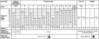
Note: The shaded area indicates the setting status at the time of purchase.
Characteristics
| Indication accuracy | Thermocouple input with cold junction compensation: (±0.1% of PV or ±1°C, whichever is greater) ±1 digit max. (See note 1.) Thermocouple input without cold junction compensation: (±0.1% FS or ±1°C, whichever is smaller) ±1 digit (See note 2.) Analog input: ±0.1% FS ±1 digit max. Platinum resistance thermometer input: (±0.1% of PV or ±0.5°C, whichever is greater) ±1 digit max. Position-proportional potentiometer input: ±5% FS ±1 digit max. |
|---|---|
| Control mode | Standard control (heating or cooling control), heating/cooling control, standard control with remote SP (2-input models only), heating/cool-ing control with remote SP (2-input models only), cascade standard control (2-input models only), cascade heating/cooling control (2- input models only), proportional control (2-input models only), position-proportional control (control-valve control models only) |
| Influence of temperature | Thermocouple input (R, S, B, W): (±1% of PV or ±10°C, whichever is greater) ±1 digit max. Other thermocouple input: (±1% of PV or ±4°C, whichever is greater) ±1 digit max. *K thermocouple at -100°C max.: ±10°C max. Platinum resistance thermometer: (±1% of PV or ±2°C, whichever is greater) ±1 digit max. Analog input: (±1%FS) ±1 digit max. |
| Influence of voltage | |
| Influence of EMS. (at EN61326-1) | |
| Control period | 0.2 to 99.0 s (in units of 0.1 s) for time-proportioning control output |
| Proportional band (P) | 0.00% to 999.99% FS (in units of 0.01% FS) |
| Integral time (I) | 0.0 to 3,999.9 s (in units of 0.1 s) |
| Derivative time (D) | 0.0 to 3,999.9 s (in units of 0.1 s) |
| Hysteresis | 0.01% to 99.99% FS (in units of 0.01% FS) |
| Manual reset value | 0.0% to 100.0% (in units of 0.1% FS) |
| Alarm setting range | -19,999 to 99,999 EU (See note 3.) (The decimal point position depends on the input type and the decimal point position setting.) |
| Input sampling period | 50 ms |
| Insulation resistance | 20 MΩ min. (at 500 VDC) |
| Dielectric strength | 2,000 VAC, 50/60 Hz for 1 min (between charged terminals of different polarities) |
| Vibration resistance (malfunction) | 10 to 55 Hz, 20 m/s2 for 10 min each in X, Y, and Z directions |
| Shock resistance (malfunction) | 100 m/s2, 3 times each in X, Y, and Z directions |
| Inrush current | 100 to 240-VAC models: 50 A max. 24 VAC/VDC models: 30 A max. |
| Weight | Controller only: Approx. 450 g; Mounting bracket: Approx. 60 g; Terminal cover: Approx. 30 g |
| Degree of protection | Front panel: NEMA4X for indoor use; Rear case: IP20; Terminals: IP00 |
| Memory protection | Non-volatile memory (number of writes: 100,000) |
| Applicable standards | UL 61010C-1, CSA C22.2 No. 1010-1 (Power supply voltage: 100 to 120 VAC): Pollution degree 2/Overvoltage category 2 EN 61010-1 (IEC 61010-1) (Power supply voltage: 100 to 240 VAC): Pollution degree 2/ Overvoltage category 2 |
| EMC | EMI: EN61326-1 (See note 4.) Radiated Interference Electromagnetic Field Strength: EN55011 Group 1 Class A Noise Terminal Voltage: EN55011 Group 1 Class A EMS: EN61326-1 (See note 4.) ESD Immunity: EN61000-4-2: 4 kV contact discharge (level 2), 8 kV air discharge (level 3) Electromagnetic Immunity: EN61000-4-3: 10 V/m (amplitude-modulated, 80 MHz to 1 GHz, 1.4 GHz to 2 GHz) (level 3) Burst Noise Immunity: EN61000-4-4:2 kV power line (level 3), 2 kV output line (relay output) (level 4), 1 kV measurement line, I/O signal line (level 4), 1 kV communications line (level 3) Conducted Disturbance Immunity: EN61000-4-6: 3 V (0.15 to 80 MHz) (level 3) Surge Immunity: EN61000-4-5:1 kV line to line (power line, output line (relay output)) (level 2), 2 kV line to ground (power line, output line (relay output)) (level 3) Power Frequency Magnetic Field Immunity: EN61000-4-8: 30 A/m (50 Hz) continuous field Voltage Dip/Interrupting Immunity: EN61000-4-11: 0.5 cycle, 100% (rated voltage) |
Note 1: K-, T-, or N-type thermocouple at −100°C max.: ±2°C ±1 digit max.
U- or L-type thermocouple: ±2°C ±1 digit max.
B-type thermocouple at 400°C max.: No accuracy specification.
R- or S-type thermocouple at 200°C max.: ±3°C ±1 digit max.
W-type thermocouple: (±0.3% of PV or ±3°C, whichever is greater) ±1 digit max.
2: U- or L-type thermocouple: ±1°C ±1 digit
R- or S-type thermocouple at 200°C max.: ±1.5°C ±1 digit
3: “EU” (Engineering Unit) represents the unit after scaling. If a temperature sensor is used, it is either °C or °F.
4: Industrial electromagnetic environment (EN/IEC 61326-1 Table 2)
Communications Specifications
| Transmission path connection | Multiple points |
|---|---|
| Communications method | RS-485 (two-wire, half duplex) |
| Synchronization method | Start-stop synchronization |
| Baud rate | 9,600, 19,200, or 38,400 bps |
| Transmission code | ASCII |
| Data bit length | 7 or 8 bits |
| Stop bit length | 1 or 2 bits |
| Error detection | Vertical parity (none, even, odd) Block check character (BCC): CompoWay/F CRC-16: Modbus |
| Flow control | None |
| Interface | RS-485 |
| Retry function | None |
| Communications buffer | 217 bytes |
| Communications response send wait time | 0 to 99 ms, Default: 20 ms |
Program Control Functions
| Number of programs (patterns) | 32 (with 8 segments/program) | |
|---|---|---|
| Number of segments (steps) | 32 (with 8 programs) | |
| Maximum number of segments | 256 | |
| Segment setting method | Time setting (Segment set with set point and time.) Gradient setting (Segment set with set point, gradient, and time.) | |
| Segment times | 0 h 0 min to 99 h 59 min 0 min 0 s to 99 min 59 s 0 min 00.0 s to 99 min 59.9 s | |
| Alarm group number specifications | Number of groups | 4 |
| Setting method | Set separately for each program. | |
| Reset operation | Select either stopping control or fixed SP operation. | |
| Startup operation | Select continuing, resetting, manual operation, run mode, or ramp back operation. | |
| PID sets | Number of sets | 8 |
| Setting method | Set separately for each program (automatic PID group selection also supported). | |
| Alarm SP function | Select from ramp SP and target SP. | |
| Program status control | Segment operation | Advance, hold, and back |
| Program operation | Program repetitions and program links | |
| Wait operation | Wait method | Select from waiting at segment ends and always waiting. |
| Wait width setting | Wait width upper limit and lower limit set separately for each program. | |
| Setting method | ON/OFF setting for each segment | |
| Time signals | Number of outputs | 6 |
| Number of ON/OFF operations | 3 each per output | |
| Setting method | Set separately for each program. | |
| Segment outputs | Number of outputs | 10 |
| Setting method | ON/OFF set for each segment. | |
| Program status output | Program end output (pulse width can be set) Segment number output | |
| Program startup operation | PV start | Select from segment 1 set point, slope-priority PV start, and time-priority PV start. |
| Standby | Standby | |
| Operation end operation | Select from resetting, continuing control at final set point, and fixed SP control. | |
| Number of event inputs | 10 max. | |
last update: August 05, 2015
OMRON E5AR-T catalog
E5AR-T Programmable Digital Controller/Catalog- Catalog
- Manual
- CAD
English
Global Edition
| Catalog Name | Catalog Number [size] | Last Update | |
|---|---|---|---|
| | - [1824KB] | Sep 15, 201620160915 | E5AR-T Data Sheet |
- NO. E5AR-T
- TYPE:Temperature Controllers General-purpose
 Copyright Statement
 - DATE:2021-06-14
- Associated products:
E5ER Digital Controllers/Features E5ER-T Programmable Digital Controller/Features