OMRON H3CR-FControl Components/ Timers/Analog Timers
OMRON H3CR-F Control Components
OMRON H3CR-F Dimensions
/Images/l_194-25-118911-198x198.jpglast update: April 15, 2013
• Wide power supply ranges of High Voltage 100 to 240 VAC/100 to 125 VDC and Low Voltage 24 to 48 VAC/12 to 48 VDC.
• ON- and OFF-times can be set independently and so combinations of long ON- or OFF-time and short OFF- or ONtime settings are possible.
• Twenty-four time ranges from 0.05 s to 300 h depending on the model to be used.
• Models with a flicker ON start or flicker OFF start are available.
• Easy sequence checks through instantaneous outputs for a zero set value at any time range.
• Length, when panel-mounted with a Socket, of 80 mm or less.
• 11-pin and 8-pin models are available.
last update: April 15, 2013
Purchase the OMRON Analog Timers Please fill in the following
If you have just landed here, this product OMRON H3CR-F Control Components,Control Components is offered online by Tianin FLD Technical Co.,Ltd. This is an online store providing Control Components at wholesale prices for consumers. You can call us or send enquiry, we would give you the prices, packing,deliverty and more detailed information on the H3CR-F We cooperate with DHL,TNT,FEDEX,UPS,EMS,etc.They guarantee to meet your needs in terms of time and money,even if you need your OMRON H3CR-FControl Components tomorrow morning (aka overnight or next day air) on your desk, 2, 3 days or more.Note to international customers, YES, we ship worldwide.
E3Z-LT / LR / LL Compact Laser Photoelectric Sensor with Built-in Amplifier/Features
E2E / E2EQ NEXT Series Proximity Sensor/Features
E2A Cylindrical Proximity Sensor/Features
M2P Indicators/Features
KM50-C Smart Power Monitor/Features
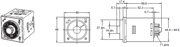
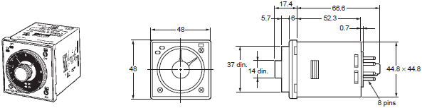
OMRON H3CR-F dimension
H3CR-F Solid-state Timer/Dimensionslast update: April 15, 2013
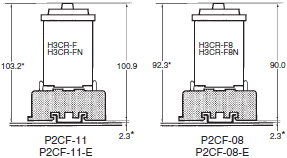
H3CR-F
H3CR-FN
H3CR-F8
H3CR-F8N
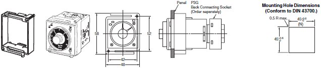
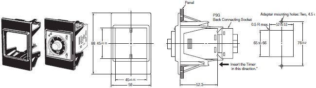
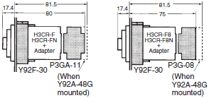
Flush Mounting Adapter
Y92F-30 Flush Mounting Adapter (Order Separately)
Note: 1. The orientation of the Adapters for two or more Timers is different for a horizontal or vertical layout. Make sure
the orientation is correct.
Consecutive Mounting of n Timers
Without Front Covers: N = (48n - 2.5) + 1 - 0
With Front Covers: N = (51n - 5.5) + 1 - 0
With Panel Covers: N = (50n - 4.5) + 1 - 0
2. The applicable thickness of the mounting panel must be 1 to 5 mm.
Y92F-73 Flush Mounting Adapter (Order Separately)
Note: A Front Cover and Flush Mounting Adapter cannot be used at the same time.
Note: The applicable thickness of the mounting panel must be 1 to 3.2 mm.
* Insert the Timer from the back of the Adapter.
Y92F-74 Flush Mounting Adapter (Order Separately)
Note: A Front Cover and Flush Mounting Adapter cannot be used at the same time.
Note: The applicable thickness of the mounting panel must be 1 to 3.2 mm.
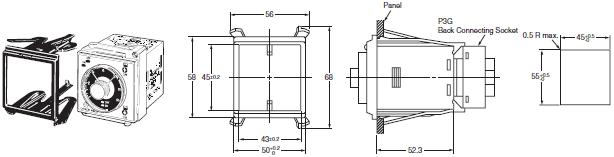
Dimensions with Front Connecting Socket
P2CF-08-[]/P2CF-11-[]
* These dimensions vary with the kind of DIN track (reference value).
Dimensions with Back Connecting Socket
P3G-08/P3GA-11
Note: There are no restrictions to the mounting direction.
last update: April 15, 2013
OMRON H3CR-F specification
H3CR-F Solid-state Timer/Specificationslast update: October 9, 2018
General
| Item | H3CR-F | H3CR-F8 | H3CR-FN | H3CR-F8N |
|---|---|---|---|---|
| Operating mode | Flicker OFF start | Flicker ON start | ||
| Pin type | 11-pin | 8-pin | 11-pin | 8-pin |
| Operating/Reset method | Time-limit operation/Time-limit reset or self-reset | |||
| Output type | Relay output (DPDT) | |||
| Mounting method | DIN track mounting, surface mounting, and flush mounting | |||
| Approved standards | UL508, CSA C22.2 No.14, NK, Lloyds, CCC: GB/T 14048.5 * Conforms to EN61812-1 and IEC60664-1 (VDE0110) 4kV/2. Output category according to EN60947-5-1. | |||
Note: For details, refer to your OMRON website.
* CCC certification requirements
| Recommended fuse | 0216005 (250VAC, 5A), manufactured by Littelfuse |
|---|---|
| Rated operating voltage Ue Rated operating current Ie | AC-15: Ue: 250 VAC, Ie: 3 A AC-13: Ue: 250 VAC, Ie: 5 A DC-13: Ue: 30 VDC, Ie: 1.5 A |
| Rated insulation voltage | 250 V |
| Rated impulse withstand voltage (altitude: 2,000 m max.) | 4 kV (at 240 VAC) |
| Conditional short-circuit current | 1000 A |
Time Ranges
| Time unit | s (sec) | ×10 s (10 sec) | min (min) | ×10 min (10 min) | h (hrs) | ×10 h (10 hrs) | |
|---|---|---|---|---|---|---|---|
| Fullscale setting | 1.2 | 0.05 to 1.2 | 1.2 to 12 | 0.12 to 1.2 | 1.2 to 12 | 0.12 to 1.2 | 1.2 to 12 |
| 3 | 0.3 to 3 | 3 to 30 | 0.3 to 3 | 3 to 30 | 0.3 to 3 | 3 to 30 | |
| 12 | 1.2 to 12 | 12 to 120 | 1.2 to 12 | 12 to 120 | 1.2 to 12 | 12 to 120 | |
| 30 | 3 to 30 | 30 to 300 | 3 to 30 | 30 to 300 | 3 to 30 | 30 to 300 | |
Note: The times that can be set are given. When the time setting knob is turned below “0” until the point where the time
setting knob stops, the output will operate instantaneously at all time range settings.
For details, refer to your OMRON website.
Ratings
| Rated supply voltage *1 *2 *3 | • 100 to 240 VAC 50/60 Hz/100 to 125 VDC • 24 to 48 VAC 50/60 Hz/12 to 48 VDC |
|---|---|
| Operating voltage range | 85% to 110% of rated supply voltage; 90% to 110% with 12-VDC models |
| Power reset | Minimum power-opening time: 0.1 s |
| Power consumption | 100 to 240 VAC: approx. 10 VA (2.1 W) at 240 VAC 24 VAC/VDC: approx. 2 VA (1.7 W) at 24 VAC, approx. 1 W at 24 VDC |
| Control outputs | Contact output: 5 A at 250 VAC/30 VDC, resistive load (cosφ = 1) The minimum applicable load is 10mA at 5VDC (P reference value). Contact materials: Ag-alloy |
*1. A power supply with a ripple of 20% max. (single-phase power supply with full-wave rectification) can be used with
each DC Model.
*2. Do not use an inverter output as the power supply. Refer to your OMRON website for details.
*3. Refer to your OMRON website when using the Timer together with a 2-wire AC proximity sensor.
Characteristics
| Accuracy of operating time | ±0.2% FS max. (±0.2% FS ±10 ms max. in ranges of 1.2 and 3 s) |
|---|---|
| Setting error | ±5% FS ±50 ms max. |
| Reset time | 0.1 s max. |
| Reset voltage | 10% max. of rated voltage |
| Influence of voltage | ±0.2% FS max. (±0.2% FS ±10 ms max. in ranges of 1.2 and 3 s) |
| Influence of temperature | ±1% FS max. (±1% FS ±10 ms max. in ranges of 1.2 and 3s) |
| Insulation resistance | 100 MΩ min. (at 500 VDC) |
| Dielectric strength | 2,000 VAC, 50/60 Hz for 1 min (between current-carrying metal parts and exposed non- current-carrying metal parts) 2,000 VAC, 50/60 Hz for 1 min (between control output terminals and operating circuit) 2,000 VAC, 50/60 Hz for 1 min (between contacts of different polarities) 1,000 VAC, 50/60 Hz for 1 min (between contacts not located next to each other) |
| Impulse withstand voltage | 5kV (between power terminals), however, 1kV for 24 to 48VAC, 12 to 48 VDC 5kV (between current-carrying terminal and exposed non-current-carrying metal parts), however 1.5 kV for 24 to 48 VAC, 12 to 48 VDC |
| Noise immunity | ±1.5 kV (between power terminals), square-wave noise by noise simulator (pulse width: 100 ns/1 μs, 1-ns rise) |
| Static immunity | Malfunction: 8 kV Destruction: 15 kV |
| Vibration resistance | Destruction: 10 to 55 Hz with 0.75-mm single amplitude for 2 hrs each in three directions Malfunction: 10 to 55 Hz with 0.5-mm single amplitude for 10 min each in three directions |
| Shock resistance | Destruction: 980 m/s2 three times each in six directions Malfunction: 98 m/s2 three times each in six directions |
| Ambient temperature | Operating: -10°C to 55°C (with no icing) Storage: -25°C to 65°C (with no icing) |
| Ambient humidity | Operating: 35% to 85% |
| Life expectancy | Mechanical: 20 million operations min. (under no load at 1,800 operations/h) Electrical: 100,000 operations min. (5 A at 250 VAC, resistive load at 1,800 operations/h) * |
| EMC | (EMI) EN61812-1 Emission Enclosure: EN55011 Group 1 class A Emission AC Mains: EN55011 Group 1 class A (EMS) EN61812-1 Immunity ESD: IEC61000-4-2 Immunity RF-interference: IEC61000-4-3 Immunity Burst: IEC61000-4-4 Immunity Surge: IEC61000-4-5 Immunity Conducted Disturbance: IEC61000-4-6 Immunity Voltage Dip/Interruption: IEC61000-4-11 |
| Case color | Light Gray (Munsell 5Y7/1) |
| Degree of protection | IP40 (panel surface) |
| Weight | Approx. 100 g |
Note: Refer to the Life-test Curve (Reference).
Life-test Curve (Reference)

Reference:
A maximum current of 0.15 A can be switched at 125 VDC (cosφ = 1) and a maximum current of 0.1A can be switched at 125V DC and L/R = 7ms.
In both cases, a life of 100,000 operations can be expected.
The minimum applicable load is 10 mA at 5 VDC (failure level: P).
last update: October 9, 2018
OMRON H3CR-F lineup
H3CR-F Solid-state Timer/Lineuplast update: April 15, 2013
| Operating modes | Supply voltage | 0.05 s to 300 h models | |
|---|---|---|---|
| 11-pin models | 8-pin models | ||
| Flicker OFF start | 100 to 240 VAC/ 100 to 125 VDC | H3CR-F 100-240AC/100-125DC | H3CR-F8 100-240AC/100-125DC |
| 24 to 48 VAC/ 12 to 48 VDC | H3CR-F 24-48AC/12-48DC | H3CR-F8 24-48AC/12-48DC | |
| Flicker ON start | 100 to 240 VAC/ 100 to 125 VDC | H3CR-FN 100-240AC/100-125DC | H3CR-F8N 100-240AC/100-125DC |
| 24 to 48 VAC/ 12 to 48 VDC | H3CR-FN 24-48AC/12-48DC | H3CR-F8N 24-48AC/12-48DC | |

Accessories (Order Separately)
Adapter, Protective Cover and Hold-down Clip
| Name/specifications | Models | |
|---|---|---|
| Flush Mounting Adapter | Y92F-30 | |
| Y92F-73 *1 | ||
| Y92F-74 *1 | ||
| Protective Cover | Y92A-48B *2 | |
| Hold-down Clip (Sold in sets of two) | For PF085A Socket | Y92H-8 |
| For PL08 or PL11 Sockets | Y92H-7 | |
Note: Refer to Operation (Common) datasheet for details.
*1 The Y92A-48B Protective Cover and the Y92F-73/-74 Flush Mounting Adapter cannot be used at the same time.
*2 The Y92A-48B Protective Cover is made from hard plastic.
Remove the Protective Cover to change the set value.
The Y92A-48B Protective Cover and the Y92F-73/-74 Flush Mounting Adapter also cannot be used at the same time.
Sockets
| Timer | Round Sockets | ||
|---|---|---|---|
| Pin | Connection | Terminal | Models |
| 11-pin | Front Connecting | DIN track mounting | P2CF-11 |
| DIN track mounting (Finger-safe type) | P2CF-11-E | ||
| Back Connecting | Screw terminal | P3GA-11 | |
| Solder terminal | PL11 | ||
| Wrapping terminal | PL11-Q | ||
| PCB terminal | PLE11-0 | ||
| 8-pin | Front Connecting | DIN track mounting | P2CF-08 |
| DIN track mounting (Finger-safe type) | P2CF-08-E | ||
| DIN track mounting | PF085A | ||
| Back Connecting | Screw terminal | P3G-08 | |
| Solder terminal | PL08 | ||
| Wrapping terminal | PL08-Q | ||
| PCB terminal | PLE08-0 | ||
Note: 1. The P2CF-[][]-E has a finger-protection structure. Round crimp terminals cannot be used. Use forked crimp
terminals.
2. The P3GA-11 and P3G-08 Socket can be used together with the Y92A-48G Terminal Cover to implement finger
protection.
3. For details, refer to your OMRON website.
Terminal Cover
| Application | Model | Remarks |
|---|---|---|
| For back connecting socket | Y92A-48G | For P3G-08 and P3GA-11 |
Note: For details, refer to your OMRON website.
last update: April 15, 2013
OMRON H3CR-F catalog
H3CR-F Solid-state Timer/Catalog- Catalog
- Manual
- CAD
English
Global Edition
| Catalog Name | Catalog Number [size] | Last Update | |
|---|---|---|---|
| | L084-E1-07 [6793KB] | Oct 09, 201820181009 | H3CR Data Sheet |
| | L130-E1-01 [2548KB] | Jun 12, 201720170612 | Model Selection Guide for Timers |
| | - [43KB] | Mar 12, 201820180312 | Recommended Replacement Periods and Periodic Replacement for Preventive Maintenance |
| | L145-E1-02 [4402KB] | Jan 07, 201920190107 | H3CR-F AC100-240/DC100-125 MAINTENANCE SHEET |
| | L146-E1-02 [4397KB] | Jan 07, 201920190107 | H3CR-F AC24-48/DC12-48 MAINTENANCE SHEET |
| | L147-E1-02 [4357KB] | Jan 07, 201920190107 | H3CR-F8 AC100-240/DC100-125 MAINTENANCE SHEET |
| | L148-E1-02 [4352KB] | Jan 07, 201920190107 | H3CR-F8 AC24-48/DC12-48 MAINTENANCE SHEET |
| | L151-E1-02 [6311KB] | Jan 07, 201920190107 | H3CR-FN AC100-240/DC100-125 MAINTENANCE SHEET |
| | L152-E1-02 [6307KB] | Jan 07, 201920190107 | H3CR-FN AC24-48/DC12-48 MAINTENANCE SHEET |
| | L149-E1-02 [6347KB] | Jan 07, 201920190107 | H3CR-F8N AC100-240/DC100-125 MAINTENANCE SHEET |
| | L150-E1-02 [6344KB] | Jan 07, 201920190107 | H3CR-F8N AC24-48/DC12-48 MAINTENANCE SHEET |
- NO. H3CR-F
- TYPE:Timers Analog Timers
 Copyright Statement
 - DATE:2021-06-09
- Associated products:
H3CR-A Solid-state Multi-functional Timers/Features H3Y Solid-state Timer/Features