
OMRON F3SR-BSafety Components/ Safety Light Curtains / Single-beam Safety Sensors/Safety Light Curtains
OMRON F3SR-B Safety Components
OMRON F3SR-B Dimensions
/Images/l_2622-25-118828-198x198.jpglast update: November 6, 2012

Ease of Use
Three intuitively recognizable indicators
Easy Beam Alignment
(World's First)
Large-size top/bottom-beam-state indicators (high intensity white LED) allows coarse adjustment.
* Research as of August 2009

(1) Adjust beam position until the TOP Top-beam-state indicator) turns ON.
(2) Adjust beam position until the BTM (Bottom-beam-state indicator) turns ON.
(3) Coarse adjustment of the beam complete when the TOP and BTM indicators turn ON.

Sensitive fine-adjustment by way of a photoelectric sensor is made using the stable-state indicator. (Green LED)
(4) Perform fine adjustment until the STB (Stable-state indicator) turns ON.
(5) Fine adjustment of the beam completes when the stable-state indicator turns ON.

New accessories for clean installation

Easy Maintenance
Intuitively recognizable error indicators
Users can easily recognize an error from simply seeing a blinking LED.

*For details on errors, refer to Data Sheet.
Easy Safety Distance Design
Response time of 15 ms fixed for all models
Calculation of the safety distances is now simple.

Robust and Reliable
Can be used in severe work environments.
Thick, impact-resistant body housing

The F3SR-B inherited MS4800's established robust, break-proof body housing structure.
IP67 degree of protection increases resistance to the environment.

IP67 degree of protection.
NBR rubber is used for sealing.

Long Distance Detection
Up to 20 meters of operating range

Operating Range is selected by a simple wiring configuration.
Two range settings: long distance (5 to 20 m) and short distance (0.3 to 7 m).
Switching of operating range can be easily set with a single input line (operating range select input).
This saves the work time for switching.
Cable installation can be as long as 100m.
It covers a wider range of applications with its easy wiring design.

Dependable
Usable Reliability in One Package
Reliability with a power supply range of 24 VDC ±20%
The F3SR-B resists momentary power interruptions and voltage drops, for reliable application.
Resistant to mutual interference
F3SR-B inherited F3SJ's highly reliable interference protection algorithm, capable of preventing mutual interference on up to three sets.
Authenticated under major safety standards including ISO 13849-1 and PLe.
Authenticated under major safety standards including European standards.

Dependable support with global network
last update: November 6, 2012
Purchase the OMRON Safety Light Curtains Please fill in the following
If you have just landed here, this product OMRON F3SR-B Safety Components,Safety Components is offered online by Tianin FLD Technical Co.,Ltd. This is an online store providing Safety Components at wholesale prices for consumers. You can call us or send enquiry, we would give you the prices, packing,deliverty and more detailed information on the F3SR-B We cooperate with DHL,TNT,FEDEX,UPS,EMS,etc.They guarantee to meet your needs in terms of time and money,even if you need your OMRON F3SR-BSafety Components tomorrow morning (aka overnight or next day air) on your desk, 2, 3 days or more.Note to international customers, YES, we ship worldwide.
ZUV Series Smart Curing System (Standard model/Multi-function model)/Features
E3NC-S Ultra-compact CMOS Smart Laser Sensor/Features
E3S-A Built-in Amplifier Photoelectric Sensor (Medium Size)/Features
NX-CSG / SL5 / SI / SO NX-series Communication Control Unit/Safety Control Units/Features
H7CX-A Multifunction Preset Counter/Features
OMRON F3SR-B catalog
F3SR-B Safety Light Curtain/Catalog- Catalog
- Manual
- CAD
English
Global Edition
| Catalog Name | Catalog Number [size] | Last Update | |
|---|---|---|---|
| | F089-E1-01 [3873KB] | Aug 05, 201420140805 | F3SR-B Catalog |
OMRON F3SR-B specification
F3SR-B Safety Light Curtain/Specificationslast update: August 20, 2014
Main Unit
| Model | F3SR-430B *1 |
|---|---|
| Sensor type | Type 4 safety light curtain |
| Applicable safety category | Category 4, 3, 2, 1, or B |
| Detection capability | Opaque objects 30 mm in diameter |
| Beam gap | 20 mm |
| Number of beams | 8 to 112 |
| Protective height | 190 to 2,270 mm |
| Lens diameter | 7 mm x 12 mm |
| Operating range *2 | For long distance wiring: 5 to 20 m For short distance wiring: 0.3 to 7 m |
| Response time | ON to OFF: 15 ms max., OFF to ON: 60 ms max. |
| Startup waiting time | 2 s max. |
| Power supply voltage (Vs) | 24 VDC±20 % (ripple p-p 10% max.) |
| Current consumption (no load) | Refer to "List of Models/Current Consumption" below. |
| Light source (emitted wavelength) | Infrared LED (870 nm) |
| Effective aperture angle (EAA) | Based on IEC61496-2. Within ±2.5° for the emitter and receiver when the operating range is 3 m or over. |
| Safety output (OSSD) | Two PNP transistor outputs, load current 500 mA max., residual voltage 2 V max. (except for voltage drop due to cable extension), leak current 1 mA max. Allowable capacity load differs depending on the total cable length as shown below. *3 100 m max.: 0.05 µF max. 70 m max.: 0.5 µF max. 50 m max.: 1.0 µF max. |
| Output operation mode | ON when receiving light |
| Input voltage | Test input, reset input, external device monitoring input, and function selection input are all ON voltage: 11 to 24 V OFF voltage: 0 to 5 V, or open Operating range selection input ON voltage: 11 to 24 V OFF voltage: 0 to 5 V |
| Input current | Test input, reset input, function selection input: 1.5 to 3 mA Operating range selection input: 1.5 to 4 mA External device monitoring input: 10 to 20 mA |
| Indicators | Refer to "Indicators" on Data Sheet. |
| Mutual interference prevention function | Interference prevention algorithm prevents mutual interference for up to three sets. |
| Test functions | Self test (when power is turned ON and while power is supplied) External test (emission stop function by test input) |
| Safety functions | External device monitor Start interlock, restart interlock |
| Connection type | Connectors (M12, 8-pin) |
| Protection circuits | Output short-circuit protection, and power supply reverse polarity protection |
| Ambient temperature | Operating: -10 to 55°C (no icing), Storage: -25 to 70°C |
| Ambient humidity | Operating: 35% to 85% (no condensation), Storage: 35% to 95% |
| Ambient operating light intensity | Incandescent lamp: 3,000 lx max. (light intensity on the receiver surface), Sunlight: 10,000 lx max. (light intensity on the receiver surface) |
| Insulation resistance | 20 MΩ (at 500 VDC) |
| Dielectric strength | 1,000 VAC 50/60 Hz, 1 min |
| Degree of protection | IP65, IP67 (IEC60529) |
| Vibration resistance | Malfunction: 10 to 55 Hz, 0.7-mm double amplitude, 20 sweeps in X, Y, and Z directions |
| Shock resistance | Malfunction: 100 m/s2, 1,000 times each in X, Y, and Z directions |
| Power supply cable | 6-mm-dia., allowable bending radius R5 mm |
| Extension cable | 6.6-mm-dia., 8-pin (0.3 mm2 × 4P, resistance 0.058 Ω/m) with braided shield, allowable bending radius R36 mm Total cable length: 100 m max. For details on twisted pairs, refer to "Single-end Connector Cable" on Data Sheet. Refer to "Double-end Connector Cable" on Data Sheet. |
| Materials | Casing: Aluminum, zinc die-cast Optical cover: PMMA resin (acrylic), cable: Oil resistant PVC |
| Weight | Model: F3SR-430B[][][][] ([]: protective height) Equation: Weight (g) = (protective height) x 4 + α The values for α are as follows: Protected height 190 mm : 1,100 Protected height 270 mm to 510 mm : 1,500 Protected height 590 mm to 1,070 mm : 2,000 Protected height 1,150 mm to 2,270 mm : 2,500 |
| Accessories | User's Manual |
| Applicable standards | EN61496-1 (Type 4 ESPE), CLC/TS61496-2 (Type 4 AOPD), EN61508-1 to 3 (SIL3), EN62061 (SIL3), EN61000-6-4 ISO13849-1 (PLe/Safety Category 4), IEC61496-1 (Type 4 ESPE), IEC61496-2 (Type 4 AOPD), IEC61508-1 to 3 (SIL3), IEC62061 (SIL3), UL application in process (as of August 1, 2009) |
*1. In the type names in this table, the contain the [][][][] 4 digits indicating the protective height (mm).
*2. Use of the Spatter Protection Cover causes a 10% maximum operating range attenuation.
*3. These values should be considered when additionally connecting elements such as capacitor that contains capacitive load.
List of Models/Current Consumption
| Model | Number of beams | Protective height (mm) | Current consumption | |||
|---|---|---|---|---|---|---|
| Emitter | Receiver (no load) | |||||
| Operating range (Short) | Operating range (Long) | Operating range (Short) | Operating range (Long) | |||
| F3SR-430B0190 | 8 | 190 | 38 mA | 44 mA | 57 mA | 64 mA |
| F3SR-430B0270 | 12 | 270 | 40 mA | 47 mA | 59 mA | 66 mA |
| F3SR-430B0350 | 16 | 350 | 42 mA | 50 mA | 60 mA | 67 mA |
| F3SR-430B0430 | 20 | 430 | 43 mA | 53 mA | 62 mA | 69 mA |
| F3SR-430B0510 | 24 | 510 | 45 mA | 57 mA | 63 mA | 70 mA |
| F3SR-430B0590 | 28 | 590 | 47 mA | 60 mA | 65 mA | 72 mA |
| F3SR-430B0670 | 32 | 670 | 48 mA | 63 mA | 66 mA | 73 mA |
| F3SR-430B0750 | 36 | 750 | 50 mA | 66 mA | 68 mA | 75 mA |
| F3SR-430B0830 | 40 | 830 | 52 mA | 69 mA | 69 mA | 76 mA |
| F3SR-430B0910 | 44 | 910 | 53 mA | 73 mA | 71 mA | 78 mA |
| F3SR-430B0990 | 48 | 990 | 55 mA | 76 mA | 72 mA | 79 mA |
| F3SR-430B1150 | 56 | 1150 | 58 mA | 82 mA | 75 mA | 82 mA |
| F3SR-430B1310 | 64 | 1310 | 61 mA | 89 mA | 78 mA | 85 mA |
| F3SR-430B1470 | 72 | 1470 | 65 mA | 95 mA | 81 mA | 88 mA |
| F3SR-430B1630 | 80 | 1630 | 68 mA | 102 mA | 84 mA | 91 mA |
| F3SR-430B1790 | 88 | 1790 | 71 mA | 108 mA | 87 mA | 94 mA |
| F3SR-430B1950 | 96 | 1950 | 74 mA | 114 mA | 91 mA | 98 mA |
| F3SR-430B2110 | 104 | 2110 | 78 mA | 121 mA | 94 mA | 101 mA |
| F3SR-430B2270 | 112 | 2270 | 81 mA | 127 mA | 97 mA | 104 mA |
Accessories
Control Unit
| Model | F3SP-B1P | |
|---|---|---|
| Power supply voltage | 24 VDC±10% | |
| Power consumption | DC1.7 W max. (not including sensor's current consumption) | |
| Operation time | 100 ms max. (not including sensor's response time) | |
| Response time | 10 ms max. (not including sensor's response time) | |
| Relay output | Number of contacts | 3NO+1NC |
| Rated load | 25 VAC, 5 A (cos Φ = 1), 30 VAC, 5 A L/R = 0 ms | |
| Rated current | 5 A | |
| Connection type | Between sensors | M12 connector (8-pin) |
| Others | Terminal block | |
| Weight (packed state) | Approx. 280 g | |
| Accessories | Instruction manual | |
Laser Pointer
| Model | F3SP-B1P |
|---|---|
| Applicable sensor | F3SR series |
| Power supply voltage | 4.65 VDC or 4.5 VDC |
| Battery | Button cell battery (SR44 or LR44) |
| Battery life * | SR44: approx. 10 continuous hours, LR44: approx. 6 continuous hours |
| Light source | Red LED laser (wavelength 650 nm, 1 mW max., JIS class 2, EN/IEC CLASS 2, FDA CLASS 2) |
| Spot diameter (typical) | 6.5 mm (at 10 m) |
| Ambient temperature | Operating: 0 to 40°C (no icing) Storage: -15 to 60°C (with no icing or condensation) |
| Ambient humidity | Operating and storage: 35% to 85% (with no condensation) |
| Material | Laser module case: aluminum Mounting part: aluminum, stainless steel |
| Weight | Approx. 250 g (packed state) |
| Accessories | Laser labels (EN: 1, FDA: 3), button cell battery (SR44: 3), instruction Sheet |
* Varies on battery type.
last update: August 20, 2014
OMRON F3SR-B lineup
F3SR-B Safety Light Curtain/Lineuplast update: August 20, 2014
Main Unit
Safety Light Curtain F3SR-430B (Type 4/PNP output)
| Application | Detection capability | Beam gap | Appearance | Operating range (Infrared light) | Number of beams | Protective height (mm) | Model |
|---|---|---|---|---|---|---|---|
| Hand/arm protection | 30-mm-dia. | 20 mm |  | Long range * 5 to 20 m | 8 to 112 | 190 to 2270 | F3SR-430B[][][][] |
| Short range * 0.3 to 7 m |
Note: Connection cable is not included in the product. You must purchase optional connector cable.
* Range is selectable via easy wiring.
Safety Light Curtain Model List
F3SR-430B Series (Detection capability: 30 mm diameter/PNP output)
| Model | Number of beams | Protective height (mm) * |
|---|---|---|
| F3SR-430B0190 | 8 | 190 |
| F3SR-430B0270 | 12 | 270 |
| F3SR-430B0350 | 16 | 350 |
| F3SR-430B0430 | 20 | 430 |
| F3SR-430B0510 | 24 | 510 |
| F3SR-430B0590 | 28 | 590 |
| F3SR-430B0670 | 32 | 670 |
| F3SR-430B0750 | 36 | 750 |
| F3SR-430B0830 | 40 | 830 |
| F3SR-430B0910 | 44 | 910 |
| F3SR-430B0990 | 48 | 990 |
| F3SR-430B1150 | 56 | 1150 |
| F3SR-430B1310 | 64 | 1310 |
| F3SR-430B1470 | 72 | 1470 |
| F3SR-430B1630 | 80 | 1630 |
| F3SR-430B1790 | 88 | 1790 |
| F3SR-430B1950 | 96 | 1950 |
| F3SR-430B2110 | 104 | 2110 |
| F3SR-430B2270 | 112 | 2270 |
* Protective height (mm) = Total sensor length
Accessories (sold separately)
Single-end Connector Cable (2 cables per set, for emitter and receiver)
For wiring with safety circuit such as single safety relay, safety relay unit, and safety controller
| Appearance | Cable length | Specifications | Model |
|---|---|---|---|
 | 3 m | M12 connector (8-pin) - 8-wire + Shield | F39-JD3A |
| 7 m | F39-JD7A | ||
| 10 m | F39-JD10A | ||
| 15 m | F39-JD15A | ||
| 20 m | F39-JD20A |
Double-end Connector Cable (2 cables per set, for emitter and receiver)
Control unit for connection with F3SP-B1P and cable extension
| Appearance | Cable length | Specifications | Model |
|---|---|---|---|
 | 0.5 m | M12 connector (8-pin) - M12 connector (8-pin) | F39-JDR5B |
| 1 m | F39-JD1B | ||
| 3 m | F39-JD3B | ||
| 5 m | F39-JD5B | ||
| 7 m | F39-JD7B | ||
| 10 m | F39-JD10B | ||
| 15 m | F39-JD15B | ||
| 20 m | F39-JD20B |
Relays with Forcibly Guided Contacts
| Type | Appearance | Specifications | Model | Remarks |
|---|---|---|---|---|
| G7SA Relays with Forcibly Guided Contacts |  | Number of poles: 4 Contact type: 2NO+2NC Rated load: 250 VAC at 6 A, 30 VDC at 6 A | G7SA-2A2B | For details on other models and socket models. |
| Number of poles: 4 Contact type: 3NO+1NC Rated load: 250 VAC at 6 A, 30 VDC at 6 A | G7SA-3A1B | |||
| G7S-[]-E Relays with Forcibly Guided Contacts |  | Number of poles: 6 Contact type: 4NO+2NC Rated load: 250 VAC at 10 A, 30 VDC at 10 A | G7S-4A2B-E | For details on other models and socket models. |
| Number of poles: 6 Contact type: 3NO+3NC Rated load: 250 VAC at 10 A, 30 VDC at 10 A | G7S-3A3B-E |
Control Unit
| Appearance | Output | Model | Remarks |
|---|---|---|---|
 | Relay, 3NO+1NC | F3SP-B1P | For connection with F3SR-B, use an F39-JD[]B double-end connector cable. |
Test rod
| Diameter | Model |
|---|---|
| 14mm dia. | F39-TRD14 |
| 20mm dia. | F39-TRD20 |
| 25mm dia. | F39-TRD25 |
| 30mm dia. | F39-TRD30 |
Laser Pointer
| Appearance | Applicable sensor | Model | Remarks |
|---|---|---|---|
 | F3SR-430B series | F39-PTR | Laser pointer for long distance beam adjustment |
Spatter Protection Cover (2 covers per set, for emitter and receiver) (Each unit reduces the operating range by 10%)
| Appearance | Applicable sensor | Model |
|---|---|---|
 | F3SR-430B series | F39-HRB[][][][] * |
* The same 4-digit numbers as the protective heights of F3SR-B ([][][][] in the light curtain type names) are substituted by [][][][] in the model names.
Note: When a spatter protection cover is mounted, the operating range of the F3SR-B is reduced by approximately 10%.
Top/Bottom Mounting Bracket (Not included with the product.)
| Appearance | Specification | Model | Application | Remarks |
|---|---|---|---|---|
 | Top/bottom mounting bracket | F39-LR1 | Top/bottom mounting bracket for F3SR-B. For side mounting and backside mounting. | 2 for emitter, 2 for receiver (total of 4 per set) |
Intermediate Mounting Bracket (Not included with the product. Purchase this bracket according to the sensor length.)
| Appearance | Specification | Model | Application | Remarks |
|---|---|---|---|---|
 | Intermediate mounting bracket | F39-LR2 | Use this bracket in combination with F3SR-B's top/bottom mounting bracket. For side mounting and backside mounting. | 1 set with 2 pieces (For the number of brackets needed, see the table below.) |
Free-Location Mounting Bracket (Not included with the product. Purchase this bracket according to the sensor length.)
| Appearance | Specification | Model | Application | Remarks |
|---|---|---|---|---|
 | Free-location mounting bracket | F39-LR3 | Use this bracket for mounting on any place without using top/bottom mounting bracket. | 1 set with 2 pieces (For the number of brackets needed, see the table below.) |
* Number of intermediate mounting brackets needed
Using top/bottom mounting bracket + intermediate mounting bracket (F39-LR2).
| Protective height (mm) | No. of top/bottom mounting brackets | No. of intermediate mounting brackets |
|---|---|---|
| 0190 to 0990 | 2 | 0 |
| 1070 to 1950 | 2 | 1 |
| 2030 to 2270 | 2 | 2 |
Using Free-location mounting bracket (F39-LR3).
| Protective height (mm) | No. of free-location mounting brackets |
|---|---|
| 0190 to 0750 | 2 |
| 0830 to 1470 | 3 |
| 1630 to 2110 | 4 |
| 2270 | 5 |
last update: August 20, 2014
OMRON F3SR-B dimension
F3SR-B Safety Light Curtain/Dimensionslast update: August 6, 2013
(Unit: mm)
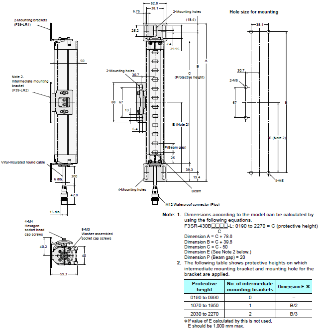
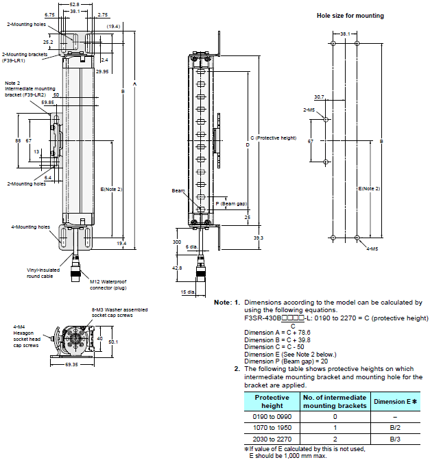
Main Unit
Using Standard Mounting Brackets
Backside mounting
Side mounting
Accessories (sold separately)
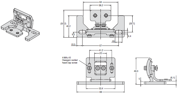
Top/bottom Mounting Bracket
F39-LR1
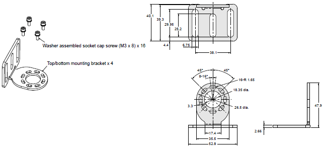
Material: Stainless steel (Top/bottom mounting brackets, hexagon socket head cap screws)
Note: Screws to mount top/bottom mounting brackets to the wall are not included.
Customers are requested to prepare them by themselves.
Intermediate Mounting Bracket
F39-LR2
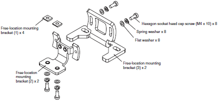
Material: Stainless steel (Free-location bracket (2),(3), hexagon socket head cap screws)
Backside mounting
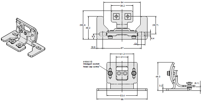
Side mounting
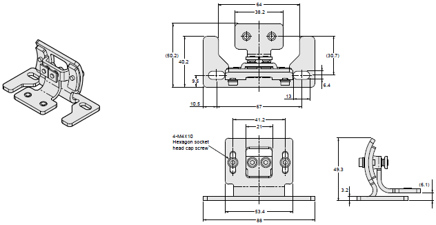
Free-location Mounting Bracket
F39-LR3
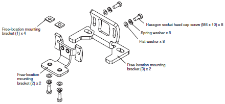
Material: Stainless steel (Free-location bracket (2),(3), hexagon socket head cap screws)
Backside mounting
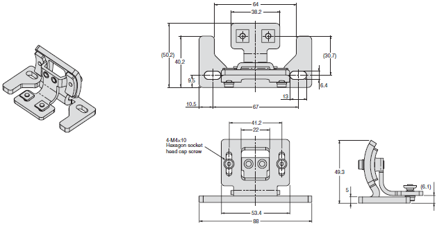
Side mounting
Number of required mounting brackets
The numbers of brackets required for the protective heights of sensors are as follows:

Single-end Connector Cable
F39-JD3A (L = 3 m), F39-JD7A (L = 7 m)
F39-JD10A (L = 10 m), F39-JD15A (L = 15 m)
F39-JD20A (L = 20 m)

Cable color: Gray for emitter, Black for receiver
Double-end Connector Cable
F39-JDR5B (L = 0.5 m), F39-JD1B (L = 1 m)
F39-JD3B (L = 3 m), F39-JD5B (L = 5 m)
F39-JD7B (L = 7 m), F39-JD10B (L = 10 m)
F39-JD15B (L = 15 m), F39-JD20B (L = 20 m)

Cable color: Gray for emitter, Black for receiver
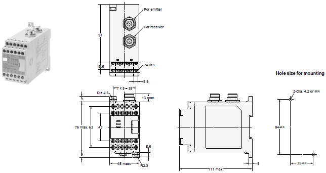
Control Unit
F3SP-B1P
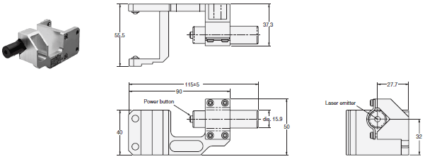
Laser Pointer
F39-PTR
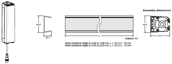
Spatter Protection Cover
F39-HRB[][][][]
last update: August 6, 2013
- NO. F3SR-B
- TYPE:Safety Light Curtains / Single-beam Safety Sensors Safety Light Curtains
 Copyright Statement
 - DATE:2021-06-12
- Associated products:
F3SJ Series Safety Light Curtain/Features MS4800 Series Safety Light Curtain/Features