
OMRON E3NC-SSensors/ Photoelectric Sensors/Separate Amplifier
OMRON E3NC-S Sensors
OMRON E3NC-S Dimensions
/Images/l_3162-25-161485-198x198.jpglast update: March 14, 2013

E3NC-SH100/SH250
A Compact Body That Delivers Stable Detection Even for Differences in Color, Material, or Surface Conditions


Laser Amplifier Units (CMOS Type)
E3NC-SA
Consistent Operating Methods for All N-Smart Amplifier Units
[Easy]
Clear, Reliable Confirmation Even from a Distance
Industry First!* White on black display characters for high visibility.
* Based on November 2012 OMRON investigation.

[Easy] [Stable]
Stable Detection of Everything But the Background
Tuning without a Workpiece
The background is used as a reference to detect everything but the reference. The surface conditions or inclination of the workpiece do not influence detection, so stable detection is maintained without changing the settings even if the workpiece is changed.

[Stable]
Malfunction Prevention for Stray Light
Background Suppression (PAT.P)


Easy Adjustment after Head Installation
Easy-to-understand Distance Display (*Target)
You can see the distance at a glance, which simplifies adjustment. After Head installation, you can reduce adjustment time after line switchovers and reduce line stoppage time.

last update: March 14, 2013
Purchase the OMRON Separate Amplifier Please fill in the following
If you have just landed here, this product OMRON E3NC-S Sensors,Sensors is offered online by Tianin FLD Technical Co.,Ltd. This is an online store providing Sensors at wholesale prices for consumers. You can call us or send enquiry, we would give you the prices, packing,deliverty and more detailed information on the E3NC-S We cooperate with DHL,TNT,FEDEX,UPS,EMS,etc.They guarantee to meet your needs in terms of time and money,even if you need your OMRON E3NC-SSensors tomorrow morning (aka overnight or next day air) on your desk, 2, 3 days or more.Note to international customers, YES, we ship worldwide.
E3F3 Photoelectric Sensor/Features
D4ER-[]N Oil-resistant Limit Switch/Features
H7AN Digital Counter (DIN 72 × 72)/Features
CJ1W-PTS CJ-series Process Analog I/O Unit/Features
CS1W-SPU01-V2 / SPU02-V2 CS-series High-speed Data Storage Unit (SPU Unit)/Features
OMRON E3NC-S lineup
E3NC-S Ultra-compact CMOS Smart Laser Sensor/Lineuplast update: August 22, 2013
Sensor Heads
| Appearance | Sensing distance | Model | Laser class |
|---|---|---|---|
 | 35 to 250 mm | E3NC-SH250H 2M | Class 2 |
| E3NC-SH250 2M | Class 1 | ||
 | 35 to 100 mm | E3NC-SH100 2M |
Amplifier Units
| Connecting method | Appearance | Inputs/outputs | Model | |
|---|---|---|---|---|
| NPN output | PNP output | |||
| Pre-wired (2 m) |  | 2 outputs + 1 input | E3NC-SA21 2M | E3NC-SA51 2M |
| Wire-saving Connector |  | 1 output + 1 input | E3NC-SA7 | E3NC-SA9 |
| M8 Connector |  | 1 output + 1 input | E3NC-SA24 | E3NC-SA54 |
| Connector for Sensor Communications Unit * |  | --- | E3NC-SA0 | |
* A Sensor Communications Unit is required if you want to use the Amplifier Unit on a network.
Accessories (Sold Separately)
Sensor Head Accessories
Sensor Head Mounting Brackets
A Mounting Bracket is not provided with the Sensor Head. It must be ordered separately as required.
| Applicable Sensor Head | Appearance | Model | Quantity | Contents |
|---|---|---|---|---|
| E3NC-SH250H E3NC-SH250 E3NC-SH100 |  | E39-L187 | 1 | Mounting Bracket: 1 Nut plate: 1 Phillips screws (M3×18): 2 |
 | E39-L188 | 1 |
Amplifier Unit Accessories
Wire-saving Connectors (Required for models for Wire-saving Connectors.)
Connectors are not provided with the Amplifier Unit and must be ordered separately.
* Protective stickers are provided.
| Type | Appearance | Cable length | No. of conductors | Model |
|---|---|---|---|---|
| Master Connector |  | 2 m | 4 | E3X-CN21 |
| Slave Connector |  | 2 | E3X-CN22 |
Sensor I/O Connectors (Required for models for M8 Connectors.)
Connectors are not provided with the Fiber Amplifier Unit and must be ordered separately.
| Size | Cable | Appearance | Cable type | Model | ||
|---|---|---|---|---|---|---|
| M8 | Standard cable | Straight |  | 2 m | 4-wire | XS3F-M421-402-A |
| 5 m | XS3F-M421-405-A | |||||
| L-shaped |  | 2 m | XS3F-M422-402-A | |||
| 5 m | XS3F-M422-405-A | |||||
Amplifier Unit Mounting Bracket
A Mounting Bracket is not provided with the Amplifier Unit. It must be ordered separately as required.
| Appearance | Model | Quantity |
|---|---|---|
 | E39-L143 | 1 |
DIN Track
A DIN Track is not provided with the Amplifier Unit. It must be ordered separately as required.
| Appearance | Type | Model | Quantity |
|---|---|---|---|
 | Shallow type, total length: 1 m | PFP-100N | 1 |
| Shallow type, total length: 0.5 m | PFP-50N | ||
| Deep type, total length: 1 m | PFP-100N2 |
End Plate
Two End Plates are provided with the Sensor Communications Unit.
End Plates are not provided with the Amplifier Unit. They must be ordered separately as required.
| Appearance | Model | Quantity |
|---|---|---|
 | PFP-M | 1 |
Related Products
Sensor Communications Units
| Type | Appearance | Model |
|---|---|---|
| Sensor Communications Unit for EtherCAT |  | E3NW-ECT |
| Sensor Communications Unit for CompoNet *1 |  | E3NW-CRT |
| Sensor Communications Unit for CC-Link *1 |  | E3NW-CCL |
| Distributed Sensor Unit *2 |  | E3NW-DS |
*1. Refer to your OMRON website for details.
*2. The Distributed Sensor Unit can be connected to any of the Sensor Communications Units.
EtherCAT® is a registered trademark and patented technology, licensed by Beckhoff Automation GmbH, Germany.
CompoNet is a registered trademark of the ODVA.
CC-Link is a registered trademark of Mitsubishi Electric Corporation. The trademark is managed by the CC-Link Partner Association.
last update: August 22, 2013
OMRON E3NC-S cad
E3NC-S Ultra-compact CMOS Smart Laser Sensor/CAD- CAD
| Product Format | Product Description | CAD Download |
|---|---|---|
| E3NC-SA21 | Amplifier Unit , Pre-Wired Type , NPN Transistor Output | |
| E3NC-SA24 | Amplifier Unit , M8 Connector Type , NPN Transistor Output | |
| E3NC-SA51 | Amplifier Unit , Pre-Wired Type , PNP Transistor Output | |
| E3NC-SA54 | Amplifier Unit , M8 Connector Type , PNP Transistor Output | |
| E3NC-SA0 | Amplifier Unit , Connector for Sensor Communications Unit Type , 2 Output | |
| E3NC-SA7 | Amplifier Unit , Wire-Saving Connector Type , NPN Transistor Output | |
| E3NC-SA9 | Amplifier Unit , Wire-Saving Connector Type , PNP Transistor Output | |
| E3NC-SH100 | Distance-Settable Type , Sensing Distance 35 to 100mm | |
| E3NC-SH250 | Distance-Settable Type , Sensing Distance 35 to 250mm , Class 1 | |
| E3NC-SH250H | Distance-Settable Type , Sensing Distance 35 to 250mm , Class 2 | |
| E3NW-CCL | Sensor Communication Unit , CC-Link | |
| E3NW-CRT | Sensor Communication Unit , CompoNet | |
| E3NW-DS | Distributed Sensor Unit | |
| E3NW-ECT | Sensor Communication Unit , EtherCAT | |
| E3X-CN21 | Wire-Saving Connector , Master Connector , 4-Wire , 2m | |
| E3X-CN22 | Wire-Saving Connector , Slave Connector , 2-Wire , 2m | |
| E39-L143 | Mounting Bracket | |
| E39-L187 | Sensor Head Mounting Bracket | |
| E39-L188 | Sensor Head Mounting Bracket | |
| PFP-100N | Supporting Rail , 1000mm | |
| PFP-100N2 | Supporting Rail , 1000mm 深型 | |
| PFP-50N | Supporting Rail , 500mm | |
| PFP-M | End Plate | |
OMRON E3NC-S dimension
E3NC-S Ultra-compact CMOS Smart Laser Sensor/Dimensionslast update: August 22, 2013
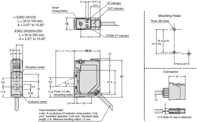
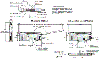
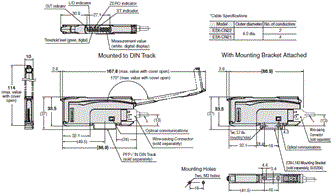
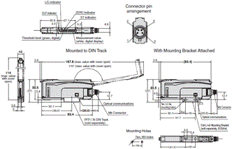
Tolerance class IT16 applies to dimensions in this data sheet unless otherwise specified.
Sensor Heads
E3NC-SH250H
E3NC-SH250
E3NC-SH100
Amplifier Units
Pre-wired Amplifier Units
E3NC-SA21
E3NC-SA51
Amplifier Units with Wire-saving Connectors
E3NC-SA7
E3NC-SA9
Amplifier Units with M8 Connectors
E3NC-SA24
E3NC-SA54
Amplifier Unit with Connector for Sensor Communications Unit
E3NC-SA0
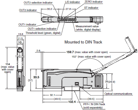
Accessories (Sold Separately)
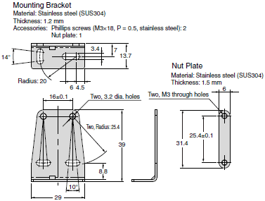
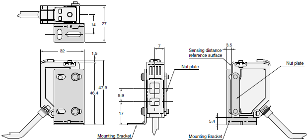
Sensor Head Mounting Brackets
E39-L187
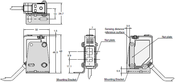
With E39-L187 Mounting Bracket Attached
E39-L188
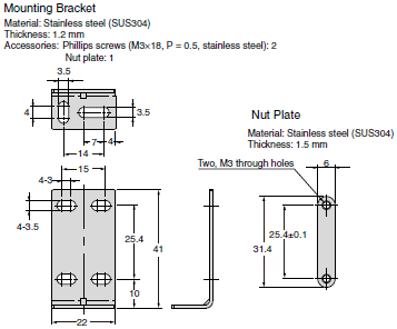
With E39-L188 Mounting Bracket Attached
Wire-saving Connector
Master Connector
E3X-CN21

* 4-dia. cable with 4 conductors, Standard cable length: 2 m (Conductor cross-section: 0.2 mm2 (AWG24), Insulation
diameter: 1.1 mm)
Slave Connector
E3X-CN22

* 4-dia. cable with 2 conductors, Standard cable length: 2 m (Conductor cross-section: 0.2 mm2 (AWG24), Insulation
diameter: 1.1 mm)
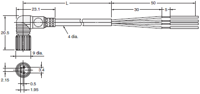
Sensor I/O Connectors
Straight
XS3F-M421-40[]-A

L-shaped
XS3F-M422-40[]-A
Amplifier Unit Mounting Bracket
E39-L143
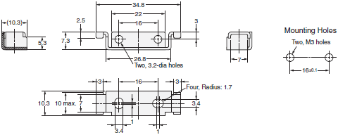
Material: Stainless steel (SUS304)
DIN Track
PFP-100N
PFP-50N

Material: Aluminum
* Dimensions in parentheses are for the PFP-50N.
PFP-100N2

Material: Aluminum
End Plate
PFP-M
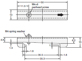
Materials: Iron, zinc plating
last update: August 22, 2013
OMRON E3NC-S specification
E3NC-S Ultra-compact CMOS Smart Laser Sensor/Specificationslast update: October 15, 2013
Sensor Heads
| Sensing method | Distance-settable | |||
|---|---|---|---|---|
| Model | E3NC-SH250H | E3NC-SH250 | E3NC-SH100 | |
| Light source (wavelength) *1 | Visible semiconductor laser diode (660 nm), 1 mW (average output: 220 μW) (JIS Class 2, IEC/EN Class 2, and FDA Class 2) | Visible semiconductor laser diode (660 nm), 0.5 mW (average output: 100 μW) (JIS Class 1, IEC/EN Class 1, and FDA Class 1) | ||
| Measurement range | 35 to 250 mm (display value: 350 to 2,500) | 35 to 100 mm (display value: 350 to 1,000) | ||
| Standard detected level difference *2 | 35 to 180mm: 9 mm 180 to 250 mm: 25 mm | 35 to 50 mm: 1.5 mm 50 to 100 mm: 3 mm | ||
| Spot diameter *3 | Approx. 1 mm (at 250 mm) | Approx. 0.5 mm (at 100 mm) | ||
| Indicators | OUT indicator (orange), STABILITY indicator (green), and ST indicator (blue) | |||
| Ambient illumination | Illumination on received light surface: 4,000 lx max. of incandescent light, 8,000 lx max. of sunlight | Illumination on received light surface: 2,000 lx max. of incandescent light, 4,000 lx max. of sunlight | Illumination on received light surface: 4,000 lx max. of incandescent light, 8,000 lx max. of sunlight | |
| Ambient temperature range | Operating: -10 to 50°C; Storage: -25 to 70°C (with no icing or condensation) | |||
| Ambient humidity range | Operating and storage: 35% to 85% (with no condensation) | |||
| Insulation resistance | 20 MΩ min. (at 500 VDC) | |||
| Dielectric strength | 1,000 VAC at 50/60 Hz for 1 min | |||
| Vibration resistance (destruction) | 10 to 55 Hz with a 1.5-mm double amplitude for 2 hours each in X, Y, and Z directions | |||
| Shock resistance (destruction) | 500 m/s2 3 times each in X, Y, and Z directions | |||
| Degree of protection | IEC IP67 | |||
| Connecting method | Pre-wired connector (Standard cable length: 2 m) | |||
| Materials | Case | Polybutylene terephthalate (PBT) | ||
| Lens | Methacrylic resin | |||
| Cable | PVC | |||
| Weight (packed state/ Sensor Head only) | Approx. 125 g/approx. 75 g | |||
| Accessories | Instruction Manual, laser warning label (E3NC-SH250H only) | |||
Note: Incorrect detection may occur outside the measurement range if the object has a high reflection factor.
*1. These Sensors are classified as Class 1 laser devices under IEC 60825-1 and the regulations of Laser Notice No. 50
for FDA certification.
CDRH (Center for Devices and Radiological Health) registration has been completed. (Accession Number:1220691)
*2. The values were measured at the center of the sensing distance using OMRON’s standard sensing object (white
ceramic).
*3. Spot diameter: Defined at the 1/e2 (13.5 %) of the central intensity at the measurement distance.
Measurement may be influenced if there is light leakage outside the defined region and the surroundings of the target
object have a high reflectance in comparison to the target object.
Also, when detecting a workpiece that is smaller than the spot diameter, a correct value may not be obtained.
Amplifier Units
| Type | Standard models | Model for Sensor Communications Unit | |||
|---|---|---|---|---|---|
| NPN output | E3NC-SA21 | E3NC-SA7 | E3NC-SA24 | E3NC-SA0 | |
| PNP output | E3NC-SA51 | E3NC-SA9 | E3NC-SA54 | ||
| Connecting method | Pre-wired | Wire-saving Connector | M8 Connector | Connector for Sensor Communications Unit | |
| Inputs/ outputs | Outputs | 2 outputs | 1 output | --- *1 | |
| External inputs | 1 input | ||||
| Power supply voltage | 10 to 30 VDC, including 10% ripple (p-p) | ||||
| Power consumption *2 | At Power Supply Voltage of 24 VDC Normal mode: 1,920 mW max. (Current consumption: 80 mA max.) Power saving eco mode: 1,680 mW max. (Current consumption: 70 mA max.) | ||||
| Control outputs *3 | Load power supply voltage: 30 VDC max., open-collector output Load current: Groups of 1 to 3 Amplifier Units: 100 mA max., Groups of 4 to 30 Amplifier Units: 20 mA max. (Residual voltage: At load current of less than 10 mA: 1 V max. At load current of 10 to 100 mA: 2 V max.) OFF current: 0.1 mA max. | --- | |||
| External inputs | Refer to *4. | ||||
| Indicators | 7-segment displays (Sub digital display: green, Main digital display: white) Display direction: Switchable between normal and reversed. OUT indicator (orange), L/D indicator (orange), ST indicator (blue), ZERO indicator (green), and OUT selection indicator (orange, only on models with 2 outputs) | ||||
| Protection circuits | Power supply reverse polarity protection, output short-circuit protection, and output reverse polarity protection | Power supply reverse polarity protection and output short-circuit protection | |||
| Response time | Super-high-speed mode (SHS) *5 | Operate or reset: 1.5 ms | |||
| High-speed mode (HS) | Operate or reset: 5 ms | ||||
| Standard mode (Stnd) | Operate or reset: 10 ms | ||||
| Giga-power mode (GIGA) | Operate or reset: 50 ms | ||||
| Sensitivity adjustment | Smart Tuning (2-point tuning, full auto tuning, 1-point tuning, tuning without workpiece, 2-point area tuning, 1-point area tuning, or area tuning without workpiece), or manual adjustment | ||||
| No. of Units for mutual interference prevention | Super-high-speed mode (SHS) *5 | 0 | |||
| High-speed mode (HS) | 2 | ||||
| Standard mode (Stnd) | 2 | ||||
| Giga-power mode (GIGA) | 2 | ||||
| Functions | Timer | Select from timer disabled, OFF-delay, ON-delay, one-shot, or ON-delay + OFF-delay timer: 1 to 9,999 ms | |||
| Zero reset | Negative values can be displayed. (Threshold value is shifted.) | ||||
| Resetting settings *6 | Select from initial reset (factory defaults) or user reset (saved settings). | ||||
| Eco mode | Select from OFF (digital displays lit) or ECO (digital displays not lit). | ||||
| Bank switching | Select from banks 1 to 4. | ||||
| Output 1 | Select from Normal detection mode, Area detection mode, or hold mode. | ||||
| Output 2 | Select from Normal detection mode or Error output mode. | --- | Select from Normal detection mode or Error output mode. | ||
| External input | Select from input OFF, tuning, laser OFF, zero reset, or bank switching. | --- | |||
| Keep function *7 | Select from ON or OFF. | ||||
| Background suppression *8 | Select from ON or OFF. | ||||
| Hysteresis width | Select from standard setting or user setting. | ||||
| Maximum connectable Units | 30 | ||||
| Ambient temperature range | Operating: Groups of 1 or 2 Amplifier Units: -25 to 55°C, Groups of 3 to 10 Amplifier Units: -25 to 50°C, Groups of 11 to 16 Amplifier Units: -25 to 45°C, Groups of 17 to 30 Amplifier Units: -25 to 40°C Storage: -30 to 70°C (with no icing or condensation) | Operating: Groups of 1 or 2 Amplifier Units: 0 to 55°C, Groups of 3 to 10 Amplifier Units: 0 to 50°C, Groups of 11 to 16 Amplifier Units: 0 to 45°C, Groups of 17 to 30 Amplifier Units: 0 to 40°C Storage: -30 to 70°C (with no icing or condensation) | |||
| Ambient humidity range | Operating and storage: 35% to 85% (with no condensation) | ||||
| Insulation resistance | 20 MΩ (at 500 VDC) | ||||
| Dielectric strength | 1,000 VAC at 50/60 Hz for 1 min | ||||
| Vibration resistance (destruction) | 10 to 55 Hz with a 1.5-mm double amplitude for 2 hours each in X, Y, and Z directions | ||||
| Shock resistance (destruction) | 500 m/s2 for 3 times each in X, Y, and Z directions | 150 m/s2 for 3 times each in X, Y, and Z directions | |||
| Weight (packed state/Amplifier Unit only) | Approx. 115 g/ approx. 75 g | Approx. 60 g/ approx. 20 g | Approx. 65 g/approx. 25 g | ||
| Materials | Case | Polycarbonate (PC) | |||
| Cover | Polycarbonate (PC) | ||||
| Cable | PVC | ||||
| Accessories | Instruction Manual | ||||
*1. Two sensor outputs are allocated in the programmable logic controller PLC I/O table.
PLC operation via Communications Unit enables reading detected values and changing settings.
*2. At Power Supply Voltage of 10 to 30 VDC.
Normal mode: 2.250 mW max. (Current consumption: 75 mA max. at 30 VDC, 145 mA max. at 10 VDC)
Power saving eco mode: 1,950 mW max. (Current consumption: 65 mA max. at 30 VDC, 125 mA max. at 10 VDC)
*3. The total for both outputs of a model with 2 outputs is 100 mA max. (Residual voltage: Load current of less than 10
mA: 1 V max., Load current of 10 to 100 mA: 2 V max.).
*4. The following details apply to the input.
| Contact input (relay or switch) | Non-contact input (transistor) | Input time | |
|---|---|---|---|
| NPN | ON: Shorted to 0 V (Sourcing current: 1 mA max.). OFF: Open or shorted to Vcc. | ON: 1.5 V max. (Sourcing current: 1 mA max.) OFF: Vcc - 1.5 V to Vcc (Leakage current: 0.1 mA max.) | ON: 9 ms min. OFF: 9 ms min. |
| PNP | ON: Shorted to Vcc (Sinking current: 3 mA max.). OFF: Open or shorted to 0 V. | ON: Vcc - 1.5 V to Vcc (Sinking current: 3 mA max.) OFF: 1.5 V max. (Leakage current: 0.1 mA max.) |
*5. The mutual interference prevention function is disabled if the detection mode is set to super-high-speed mode.
*6. The bank is not reset by the user reset function or saved by the user save function.
*7. The output for a measurement error is set. ON: The value of the output from before the measurement error is
retained. OFF: The output is turned OFF when a measurement error occurs.
*8. Only the sensing object is detected when tuning.
last update: October 15, 2013
- NO. E3NC-S
- TYPE:Photoelectric Sensors Separate Amplifier
 Copyright Statement
 - DATE:2021-06-10
- Associated products:
E3NC-L Compact Smart Laser Sensor/Features E3ZR-C Oil-resistant Photoelectric Sensors/Features