OMRON ZSwitches/ Basic Switches/Basic Switches (Z-Size)
OMRON Z Switches
OMRON Z Dimensions
/Images/l_289-25-119075-198x198.jpglast update: December 19, 2013
• A large switching capacity of 15 A with high repeat accuracy.
• A wide range of variations in contact form for your selection: basic, split-contact, maintained-contact, and adjustable contact gap types.
• A series of standard models for micro loads is available.
• A series of molded terminal-type models incorporating safety terminal protective cover is available.
last update: December 19, 2013
Purchase the OMRON Basic Switches (Z-Size) Please fill in the following
If you have just landed here, this product OMRON Z Switches,Switches is offered online by Tianin FLD Technical Co.,Ltd. This is an online store providing Switches at wholesale prices for consumers. You can call us or send enquiry, we would give you the prices, packing,deliverty and more detailed information on the Z We cooperate with DHL,TNT,FEDEX,UPS,EMS,etc.They guarantee to meet your needs in terms of time and money,even if you need your OMRON ZSwitches tomorrow morning (aka overnight or next day air) on your desk, 2, 3 days or more.Note to international customers, YES, we ship worldwide.
E2EQ-[]-IL[] IO-Link Proximity Sensor (Spatter-resistant Models)/Features
E2CY-SD Non-ferrous-metal-detecting Proximity Sensor (Separate Amplifier Type)/Features
V680S Series RFID System/Features
GX-ILM08C GX-series IO-Link Master Unit/Features
S8VK-C Switch Mode Power Supply (60/120/240/480-W Models)/Features
OMRON Z dimension
Z General-purpose Basic Switch/Dimensionslast update: December 18, 2015
Mounting
Use M4 screws with plane washers and spring washers to mount the Switch. Tighten each mounting screw securely to a torque of 1.18 to 1.47 Nm.

When mounting the Switch to a panel, use a tightening torque of 2.94 to 4.9 Nm for the hexagonal nuts on the actuator.
Basic Models (General-purpose) and Split-contact Models
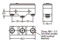
Terminals
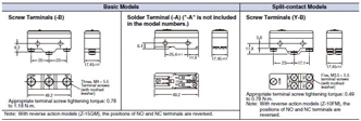
The models, illustrations, and graphics are for screw-terminal models (-B). The "-A" at the end of the model number for solder terminal models has been omitted. For details of the terminals, see above.
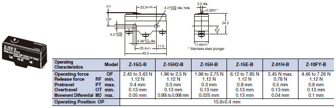
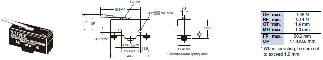
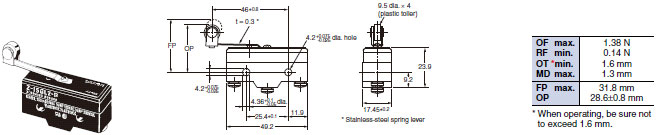
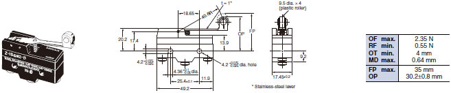
Pin Plunger
Z-15G-B, Z-15E-B
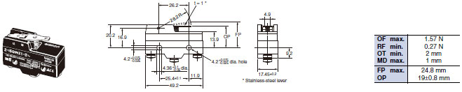
Z-15H2-B, Z-01H-B
Z-15H-B, Z-10FY-B
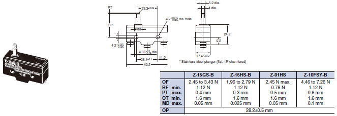
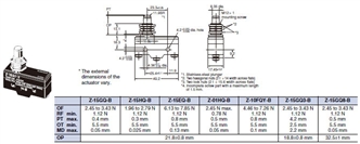
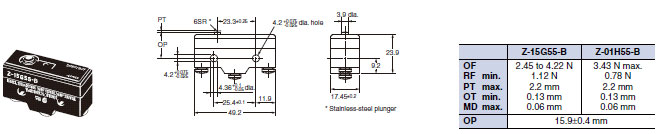
Slim Spring Plunger
Z-15GS-B, Z-01HS-B
Z-15HS-B, Z-10FSY-B
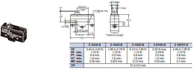
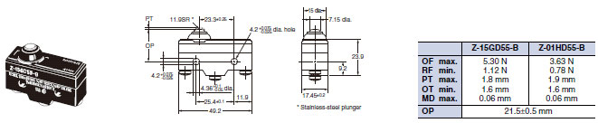
Short Spring Plunger
Z-15GD-B, Z-01HD-B
Z-15HD-B, Z-10FDY-B
Z-15ED-B
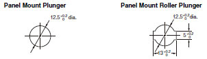
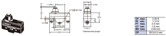
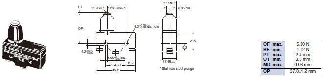
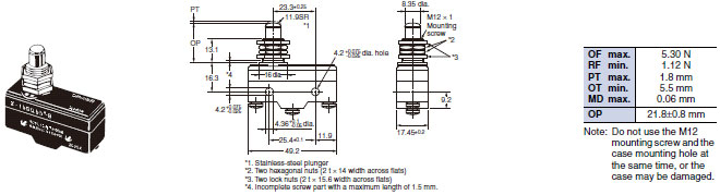
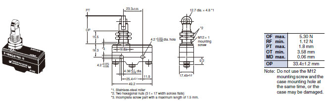
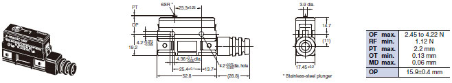
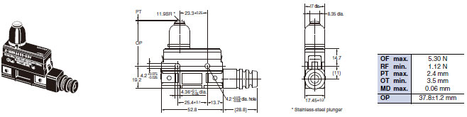
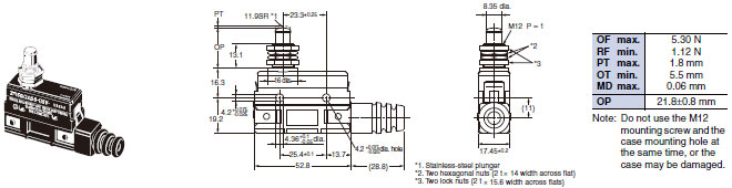
Panel Mount Plunger
Z-15GQ-B, Z-01HQ-B
Z-15HQ-B, Z-10FQY-B
Z-15EQ-B, Z-15GQ3-B *
Z-15GQ8-B *
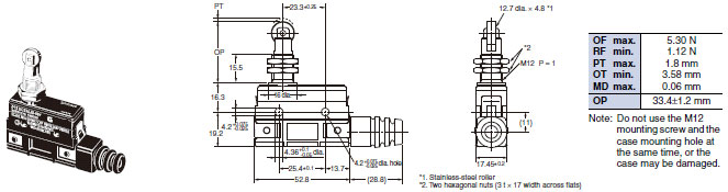
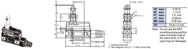
Note: 1. Do not use the M12 mounting screw and the case mounting hole at the same time, or excessive pulling force will
be imposed on the switch and the case and cover may be damaged.
2. On the model Z-15GQ3-B, PT can be set to a value larger than that for the Z-15GQ.
3. On the model Z-15GQ8-B, operating position can be adjusted by providing a screw in the plunger section.
4. On the model Z-15GQ8-B, the M3 hole with a depth of 10 mm is a through hole. Take precautions so that no
water or screw lock agent penetrates into the hole.
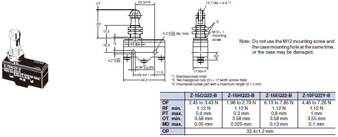
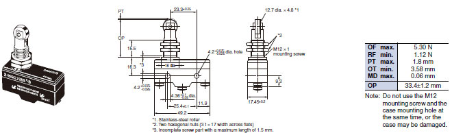
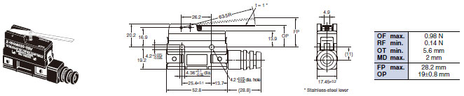
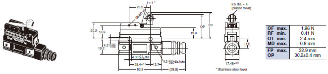
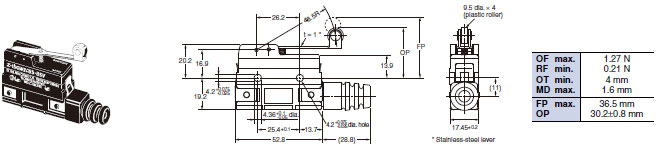
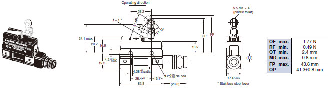
Panel Mount Roller Plunger
Z-15GQ22-B, Z-15EQ22-B
Z-15HQ22-B, Z-10FQ22Y-B
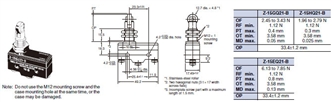
Panel Mount Cross Roller Plunger
Z-15GQ21-B, Z-15EQ21-B
Z-15HQ21-B
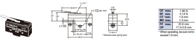
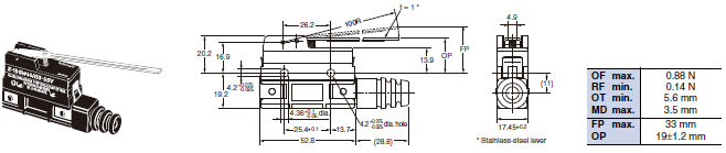
Leaf Spring
Z-15GL-B
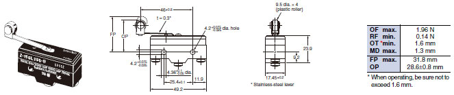
Roller Leaf Spring
Z-15GL2-B
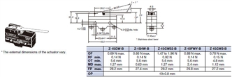
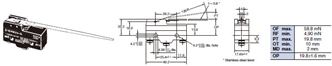
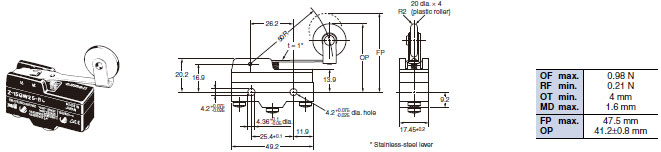
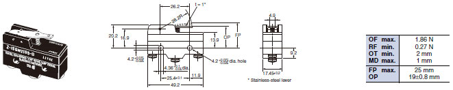
Short Hinge Lever
Z-15GW21-B
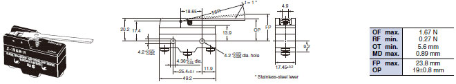
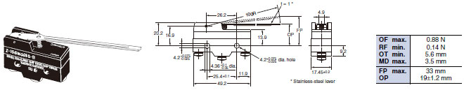
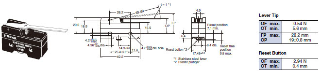
Hinge Lever
Z-15GW-B, Z-15GW32-B
Z-15HW-B, Z-10FWY-B
Z-15GW3-B (Lever Length: 56R) *
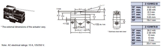
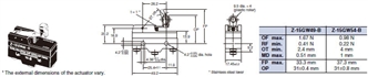
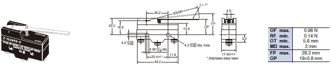
Low-force Hinge Lever
Z-15GW4-B
Z-15HW24-B
Low-force Wire Hinge Lever
Z-15HW52-B
Z-15HW78-B (Lever Length: 110R) *
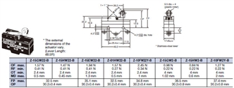
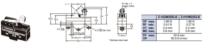
Short Hinge Roller Lever
Z-15GW22-B, Z-01HW22-B
Z-15HW22-B, Z-10FW22Y-B
Z-15EW22-B
Z-15GW2-B *, Z-15HW2-B *
Z-10FW2Y-B *
Short Hinge Cross Roller Lever
Z-15GW49-B
Z-15GW54-B (Lever Length: 48.7R) *
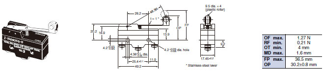
Hinge Roller Lever
Z-15GW25-B
Unidirectional Short Hinge Roller Lever
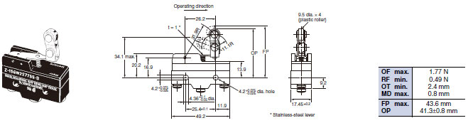
Z-15GW2277-B

Reverse Hinge Lever **
Z-15GM-B
Reverse Short Hinge Roller Lever **
Z-15GM22-B
Z-10FM22Y-B
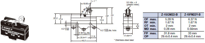
Reverse Hinge Roller Lever **
Z-15GM2-B
** The pin plungers of reverse-type models are continuously pressed by the actuator levers with compression coil
springs and the pin plungers are freed by operating the levers. Reverse-type models are highly vibration- and shock-
resistive because the pin plungers are normally pressed.
Basic Models (Drip-proof) without Terminal Protective Cover
Terminals
Without Terminal Protective Cover
Note: With reverse action models (Z-15GM), the positions of NO and NC terminals are reversed.
The above illustration is for model without terminal protective cover.
Pin Plunger
Z-15G55-B
Z-01H55-B
Short Spring Plunger
Z-15GD55-B
Z-01HD55-B
Spring Plunger
Z-15GK55-B
Z-15GK355-B
Panel Mount Plunger
Z-15GQ55-B
Panel Mount Roller Plunger
Z-15GQ2255-B
Panel Mount Cross Roller Plunger
Z-15GQ2155-B
Leaf Spring
Z-15GL55-B
Roller Leaf Spring
Z-15GL255-B
Short Hinge Lever
Z-15GW2155-B
Long Hinge Lever
Z-15GW4455-B
Hinge Lever
Z-15GW55-B
Short Hinge Roller Lever
Z-15GW2255-B
Z-01HW2255-B
Hinge Roller Lever
Z-15GW255-B
Unidirectional Short Hinge Roller Lever
Z-15GW227755-B
Reverse Hinge Lever *
Z-15GM55-B
Reverse Short Hinge Roller Lever *
Z-15GM2255-B
Reverse Hinge Roller Lever *
Z-15GM255-B
* The pin plungers of reverse-type models are continuously pressed by the actuator levers with compression coil springs
and the pin plungers are freed by operating the levers.
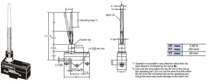
Flexible Rod (Coil Spring)
Z-15GNJ55-B
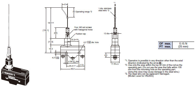
Flexible Rod (Steel Wire)
Z-15HNJS55-B
Basic Models (Drip-proof) with Terminal Protective Cover
Pin Plunger
Z-15GA55-B5V
Z-15GK3A55-B5V
Panel Mount Plunger
Z-15GQA55-B5V
Panel Mount Roller Plunger
Z-15GQ22A55-B5V
Panel Mount Cross-roller Plunger
Z-15GQ21A55-B5V
Long Hinge Lever
Z-15GW44A55-B5V
Hinge Lever
Z-15GWA55-B5V
Short Hinge Roller Lever
Z-15GW22A55-B5V
Hinge Roller Lever
Z-15GW2A55-B5V
Unidirectional Short Hinge Roller Lever
Z-15GW2277A55-B5V
Basic Models (Drop-proof) with Modeled terminals
Molded Terminals
L/R Type (The following illustration is the R type.)
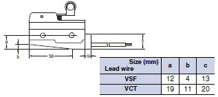
D Type
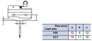
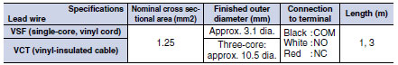
Lead Wire Specifications
Note: 1. No models with molded terminals are approved by UL, CSA, or EN.
2. Molded terminals are not available on all models. Contact your OMRON representative for applicable products.
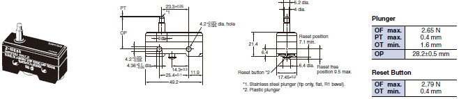
Maintained-contact Models
Pin Plunger
Z-15ER

Slim Spring Plunger
Z-15ESR
Hinge Lever
Z-15EWR
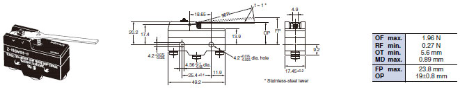
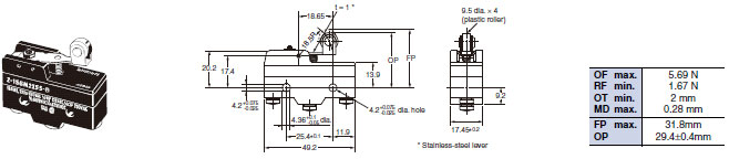
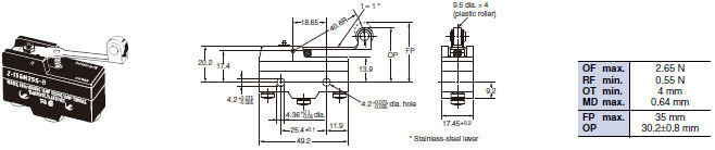
Note: Unless otherwise specified, a tolerance of ±0.4 mm applies to all dimensions.
Accessories (Order Separately)
Drip-proof Terminal Cover
AP-DV
Terminal Covers
AP-A
Soldering Terminal Use (Phenol Resin)
Note: The Cover has five thin, easy-to-separate portions for easy lead wire connections.
AP-B
Screw Terminal Use (Phenol Resin)
Note: The Cover has six thin, easy-to-separate portions for easy lead wire connections.
AP1-A
Soldering Terminal Use (Metal Press Mold)
Note: The Cover has five holes for easy lead wire connections.
AP1-B
Screw Terminal Use (Metal Press Mold)
Note: The Cover has six holes for easy lead wire connections.
AP-Z
Soldering or Screw Terminal Use (Vinyl Chloride)
Note: Each dimension has a tolerance of ±0.4 mm unless otherwise specified. (±0.8 mm for the AP-Z)
Separator
SEPARATOR FOR Z
Note: 1. Each dimension has a tolerance of ±0.4 mm unless otherwise specified.
2. The material is EAVTC (Epoxide Alkyd Varnished Tetron Cloth) and its heat-resisting temperature is 130°C.
Actuators
Hinge Lever
XAA-1

Hinge Roller Lever
ZAA-2
Short Panel Mount Plunger
ZAQ-3
Medium Panel Mount Plunger
ZAQ-2
Long Panel Mount Plunger
ZAQ-1
Panel Mount Roller Plunger
ZAQ-22
Note: Each dimension has a tolerance of ±0.4 mm unless otherwise specified.
last update: December 18, 2015
OMRON Z specification
Z General-purpose Basic Switch/Specificationslast update: September 16, 2015
Ratings (Basic, Split-contact and Maintained contact Models)
Z-15 (Except Micro Load and Flexible Rod Models)
| Item | Non-inductive load (A) | Inductive load (A) | |||||||
|---|---|---|---|---|---|---|---|---|---|
| Resistive load | Lamp load | Inductive load | Motor load | ||||||
| Contact gap | Rated voltage | NC | NO | NC | NO | NC | NO | NC | NO |
| G, H, H2, E | 125 VAC 250 VAC 500 VAC * | 15 (10) * 15 (10) * 10 | 3 2.5 2.5 | 1.5 1.25 0.75 | 15 (10) * 15 (10) * 6 | 5 3 1.5 | 2.5 1.5 0.75 | ||
| G | 8 VDC 14 VDC 30 VDC 125 VDC 250 VDC | 15 15 6 0.5 0.25 | 3 3 3 0.5 0.25 | 1.5 1.5 1.5 0.5 0.25 | 15 10 5 0.05 0.03 | 5 5 5 0.05 0.03 | 2.5 2.5 2.5 0.05 0.03 | ||
| H, H2 | 8 VDC 14 VDC 30 VDC 125 VDC 250 VDC | 15 15 2 0.4 0.2 | 3 3 2 0.4 0.2 | 1.5 1.5 1.4 0.4 0.2 | 15 10 1 0.03 0.02 | 5 5 1 0.03 0.02 | 2.5 2.5 1 0.03 0.02 | ||
| E | 8 VDC 14 VDC 30 VDC 125 VDC 250 VDC | 15 15 15 0.75 0.3 | 3 3 3 0.75 0.3 | 1.5 1.5 1.5 0.75 0.3 | 15 15 10 0.4 0.2 | 5 5 5 0.4 0.2 | 2.5 2.5 2.5 0.4 0.2 | ||
* Figures in parentheses are for the Z-15HW52, Z-15HW78(-B) and Z-15H2(-B) models, the AC ratings of these models
are 125 and 250 V only.
Z-15 (Flexible Rod Models)
| Rated voltage | Non-inductive load (A) | Inductive load (A) | ||||||
|---|---|---|---|---|---|---|---|---|
| Resistive load | Lamp load Inductive load Motor load | Lamp load Inductive load | Motor load | |||||
| NC | NO | NC | NO | NC | NO | NC | NO | |
| 125 VAC 250 VAC | 15 15 | 2 1 | 1 0.5 | 7 5 | 2.5 1.5 | 2 1 | ||
| 8 VDC 14 VDC 30 VDC 125 VDC 250 VDC | 15 15 2 0.4 0.2 | 2 2 2 0.4 0.2 | 1 1 1 0.4 0.2 | 7 7 1 0.03 0.02 | 3 3 1 0.03 0.02 | 1.5 1.5 0.5 0.03 0.02 | ||
Z-10F
| Item | Non-inductive load (A) | Inductive load (A) | |||||||
|---|---|---|---|---|---|---|---|---|---|
| Resistive load | Lamp load | Inductive load | Motor load | ||||||
| Contact gap | Rated voltage | NC | NO | NC | NO | NC | NO | NC | NO |
| Series connection | 125 VAC 250 VAC | 10 10 | 4 2.5 | 2 1.5 | 6 6 | 5 3 | 2.5 1.5 | ||
| 30 VDC 125 VDC 250 VDC | 10 1 0.6 | 4 1 0.6 | 2 1 0.6 | 6 0.1 0.05 | 6 0.1 0.05 | 3 0.1 0.05 | |||
| Parallel connection | 125 VAC 250 VAC | 6 6 | 3 2.5 | 1.5 1.25 | 4 4 | 4 2 | 2 1 | ||
| 30 VDC 125 VDC 250 VDC | 6 0.6 0.3 | 4 0.6 0.3 | 2 0.6 0.3 | 4 0.1 0.05 | 6 0.1 0.05 | 3 0.1 0.05 | |||
Z-01H
| Rated voltage | Resistive load (A) | |
|---|---|---|
| NC | NO | |
| 125 VAC | 0.1 | |
| 8 VDC | 0.1 | |
| 14 VDC | 0.1 | |
| 30 VDC | 0.1 | |
Note: 1. The above current ratings are the values of the steady-state current.
2. Inductive load has a power factor of 0.4 min. (AC) and a time constant of 7 ms max. (DC).
3. Lamp load has an inrush current of 10 times the steady-state current.
4. Motor load has an inrush current of 6 times the steady-state current.
5. The normally closed and normally open ratings of reverse hinge lever models are opposite to each other.
6. The AC ratings of molded terminals are 125 and 250 V only.
7. The ratings values apply under the following test conditions:
(1) Ambient temperature: 20±2°C
(2) Ambient humidity: 65±5%RH
(3) Operating frequency: 20 operations/min
Use the switch within the operating range.
| Z-01H | Z-15[], Z-10FY | |
|---|---|---|
| Minimum applicable load | 5 VDC 1 mA | 5 VDC 160 mA |
Characteristics
| Classification | Z-15 (except micro load and flexible rod) | Z-01H | Z-15 (flexible rod) | Z-10F | Z-15H2 | |
|---|---|---|---|---|---|---|
| Operating speed | 0.01 mm to 1 m/s *1 | 1 mm to 1 m/s | 0.1 mm to 1 m/s *1 | 0.01 mm to 1 m/s | ||
| Operating frequency | Mechanical | 240 operations/min | 120 operations/min | 240 operations/min | 240 operations/min | |
| Electrical | 20 operations/min | |||||
| Insulation resistance | 100 MΩ min. (at 500 VDC) | |||||
| Contact resistance | 15 mΩ max. (initial value) | 50 mΩ max. (initial value) | 15 mΩ max. (initial value) | 25 mΩ max. (initial value) | 15 mΩ max. (initial value) | |
| Dielectric strength | Between contacts of same polarity Contact gap G: 1,000 VAC, 50/60 Hz for 1 min Contact gap H: 600 VAC, 50/60 Hz for 1 min Contact gap E: 1,500 VAC, 50/60 Hz for 1 min | Between contacts of same polarity Contact gap G: 1,000 VAC, 50/60 Hz for 1 min Contact gap H: 600 VAC, 50/60 Hz for 1 min | Between contacts of same polarity Contact gap F: 1,500 VAC, 50/60 Hz for 1 min | Between contacts of same polarity 600VAC, 50/60Hz for 1 min | ||
| Between current-carrying metal parts and ground, and between each terminal and non-current-carrying metal parts 2,000 VAC, 50/60 Hz for 1 min | ||||||
| Vibration resistance | Malfunction | 10 to 55 Hz, 1.5-mm double amplitude * 5 | 10 to 20 Hz, 1.5-mm double amplitude *5 | 10 to 55 Hz, 1.5-mm double amplitude *5 | ||
| Shock resistance | Destruction | 1,000 m/s2 max. | ||||
| Malfunction | 300 m/s2 max. *2 *5 | 50 m/s2 max. *5 | 300 m/s2 max. *3 *5 | 100 m/s2 max. | ||
| Durability | Mechanical | Contact gap G, H: 20,000,000 operations min. Contact gap E: 300,000 operations | 1,000,000 operations min. | 500,000 operations min. *1 | 20,000,000 operations min. | |
| Electrical | Contact gap G, H: 500,000 operations min. Contact gap E: 100,000 operations min. | 100,000 operations min. | 100,000 operations min. | 500,000 operations min. | ||
| Degree of protection | General- purpose | IP00 | ||||
| Drip-proof | Equivalent to IP62 (except terminals) | |||||
| Degree of protection against electric shock | Class I | |||||
| Proof tracking index (PTI) | 175 | |||||
| Ambient operating temperature | General- purpose | - 25 °C to 80 °C (with no icing) | ||||
| Drip-proof | - 15 °C to 80 °C (with no icing) | |||||
| Ambient operating humidity | General- purpose | 35% to 85%RH | ||||
| Drip-proof | 35% to 95%RH | |||||
| Weight | Approx. 22 to 58 g | Approx. 42 to 48 g | Approx. 34 to 61 g | Approx. 22 g | ||
*1. The values are for the plunger models. (For the lever models, the values are at the plunger section.) (Consult your
OMRON representative for other models.)
*2. The values are for the Z-15G pin plunger.
*3. The values are for the Z-10FY-B.
*4. The values are for the pin plunger. The durability for models other than the pin plunger is 10,000,000 min.
*5. Malfunction: 1 ms max.
Contacts Specification
| Item | Classification | Z-15 | Z-01H | Z-10F |
|---|---|---|---|---|
| Contacts | Shape | Rivet | Single crossbar | Rivet |
| Material | Silver | Gold alloy | Silver | |
| Inrush current | NC | 30 A max. | 0.1 A max. | 40 A max. |
| NO | 15 A max. | 0.1 A max. | 20 A max. |
last update: September 16, 2015
OMRON Z catalog
Z General-purpose Basic Switch/Catalog- Catalog
- CAD
English
Global Edition
| Catalog Name | Catalog Number [size] | Last Update | |
|---|---|---|---|
| | - [7080KB] | Apr 01, 201620160401 | Z Data Sheet |
OMRON Z lineup
Z General-purpose Basic Switch/Lineuplast update: December 18, 2015
Main Unit
Basic Models (General-purpose)
| Actuator | Classification | Standard | High-sensitivity | Extra-high sensitivity | High-capacity | Micro load | ||
|---|---|---|---|---|---|---|---|---|
| Contact gap | G (0.5 mm) | H (0.25 mm) | H2 (0.20 mm) | E (1.8 mm) | H (0.25 mm) | |||
| Terminal *1 | Model | Model | Model | Model | Model | |||
| Pin plunger |  |  | Z-15G | Z-15H | Z-15H2 | Z-15E | Z-01H | |
 | Z-15G-B | Z-15H-B | Z-15H2-B | Z-15E-B | Z-01H-B | |||
| Slim spring plunger |  | | Z-15GS | Z-15HS | --- | --- | Z-01HS | |
| Z-15GS-B | Z-15HS-B | Z-01HS-B | |||||
| Short spring plunger |  | | Z-15GD | Z-15HD | --- | Z-15ED | Z-01HD | |
| Z-15GD-B | Z-15HD-B | Z-15ED-B | Z-01HD-B | ||||
| Panel mount plunger |  | Low OP | | Z-15GQ3 | --- | --- | --- | --- |
| Z-15GQ3-B | |||||||
| Medium OP | | Z-15GQ | Z-15HQ | Z-15EQ | Z-01HQ | |||
| Z-15GQ-B | Z-15HQ-B | Z-15EQ-B | Z-01HQ-B | ||||
| High OP | | Z-15GQ8 | --- | --- | --- | |||
| Z-15GQ8-B | |||||||
| Panel mount roller plunger |  | | Z-15GQ22 | Z-15HQ22 | --- | Z-15EQ22 | --- | |
| Z-15GQ22-B | Z-15HQ22-B | Z-15EQ22-B | |||||
| Panel mount cross roller plunger |  | | Z-15GQ21 | Z-15HQ21 | --- | Z-15EQ21 | --- | |
| Z-15GQ21-B | Z-15HQ21-B | Z-15EQ21-B | |||||
| Leaf spring |  | | Z-15GL | --- | --- | --- | --- | |
| Z-15GL-B | |||||||
| Roller leaf spring |  | | Z-15GL2 | --- | --- | --- | --- | |
| Z-15GL2-B | |||||||
| Short hinge lever |  | | Z-15GW21 | --- | --- | --- | --- | |
| Z-15GW21-B | |||||||
| Hinge lever |  | Low OP | | Z-15GW | Z-15HW | --- | --- | --- |
| Z-15GW-B | Z-15HW-B | ||||||
| Medium OP | | Z-15GW3 | --- | |||||
| Z-15GW3-B | |||||||
| High OP | | Z-15GW32 | ||||||
| Z-15GW32-B | |||||||
| Low-force hinge lever |  | | Z-15GW4 | Z-15HW24 | --- | --- | --- | |
| Z-15GW4-B | Z-15HW24-B | ||||||
| Low-force wire hinge lever |  | Low OP | | --- | Z-15HW78 | --- | --- | --- |
| Z-15HW78-B | |||||||
| High OP | | Z-15HW52 | ||||||
| Z-15HW52-B | |||||||
| Short hinge roller lever |  | | Z-15GW22 | Z-15HW22 | --- | Z-15EW22 | Z-01HW22 | |
| Z-15GW22-B | Z-15HW22-B | Z-15EW22-B | Z-01HW22-B | ||||
| Short hinge cross roller lever |  | | Z-15GW49 | --- | --- | --- | --- | |
| Z-15GW49-B | |||||||
| Hinge roller lever |  | Standard | | Z-15GW2 | Z-15HW2 | --- | --- | --- |
| Z-15GW2-B | Z-15HW2-B | ||||||
| Large roller | | Z-15GW25 | --- | --- | --- | |||
| Z-15GW25-B | |||||||
| Hinge cross roller lever |  | | Z-15GW54 | --- | --- | --- | --- | |
| Z-15GW54-B | |||||||
| Unidirectional short hinge roller lever |  | Parallel | | Z-15GW2277 | --- | --- | --- | --- |
| Z-15GW2277-B | |||||||
| Reverse hinge lever *2 |  | | Z-15GM | --- | --- | --- | --- | |
| Z-15GM-B | |||||||
| Reverse short hinge roller lever *2 |  | | Z-15GM22 | --- | --- | --- | --- | |
| Z-15GM22-B | |||||||
| Reverse hinge roller lever *2 |  | | Z-15GM2 | --- | --- | --- | --- | |
| Z-15GM2-B | |||||||

*2. The pin plungers of reverse-type models are continuously pressed by the actuator levers with compression coil
springs and the pin plungers are freed by operating the levers. Reverse-type models are highly vibration- and shock-
resistive because the pin plungers are normally pressed.
Minimum Order Lot
The following models are available at the minimum order lot specified below.
Orders must be placed per lot.
| Classification | Standard | High-sensitivity | Minimum order lot (pcs) |
|---|---|---|---|
| Short spring plunger | Z-15GD-B | --- | 10 |
| Panel mount plunger | Z-15GQ Z-15GQ-B Z-15GQ8-B | --- | |
| Panel mount roller plunger | Z-15GQ22 Z-15GQ22-B | --- | |
| Panel mount cross roller plunger | Z-15GQ21-B | --- | |
| Short hinge lever | Z-15GW21-B | --- | |
| Hinge lever | Z-15GW Z-15GW-B | --- | |
| Low-force hinge lever | Z-15GW4-B | Z-15HW24-B | |
| Low-force hinge wire lever | --- | Z-15HW78-B | |
| Short hinge roller lever | Z-15GW22 Z-15GW22-B | --- | |
| Hinge roller lever | Z-15GW2 Z-15GW2-B | --- | |
| Reverse short hinge roller lever | Z-15GM22-B | --- | |
| Reverse hinge roller lever | Z-15GM2-B | --- |
Split-contact Models
| Actuator | Contact gap Terminal *1 | F (1.0 mm) | |
|---|---|---|---|
| Model | |||
| Pin plunger |  |  | --- |
 | Z-10FY-B | ||
| Slim spring plunger |  | | --- |
| Z-10FSY-B | ||
| Short spring plunger |  | | --- |
| Z-10FDY-B | ||
| Panel mount plunger |  | | --- |
| Z-10FQY-B | ||
| Panel mount roller plunger |  | | --- |
| Z-10FQ22Y-B | ||
| Hinge lever |  | | --- |
| Z-10FWY-B | ||
| Short hinge roller lever |  | | --- |
| Z-10FW22Y-B | ||
| Hinge roller lever |  | | --- |
| Z-10FW2Y-B | ||
| Reverse short hinge roller lever *2 |  | | --- |
| Z-10FM22Y-B | ||

*2. The pin plungers of reverse-type models are continuously pressed by the actuator levers with compression coil
springs and the pin plungers are freed by operating the levers. Reverse-type models are highly vibration- and shock-
resistive because the pin plungers are normally pressed.
Maintained-contact Models
| Actuator | Model | |
|---|---|---|
| Pin plunger |  | Z-15ER |
| Slim spring plunger |  | Z-15ESR |
| Hinge lever |  | Z-15EWR |
Basic Models (Drip-proof Models (Standard, Microload))
| Actuator | Classification | Standard | Micro load | |||
|---|---|---|---|---|---|---|
| Contact gap | G (0.5 mm) | H (0.25 mm) | ||||
| Drip-proof terminal protective cover | Not provided | Provided | Not provided | |||
| Terminal *1 | Model | Model | Model | |||
| Pin plunger |  |  | Z-15G55 | --- | Z-01H55 | |
 | Z-15G55-B | Z-15GA55-B5V | Z-01H55-B | |||
| Short spring plunger |  | | Z-15GD55 | --- | Z-01HD55 | |
| Z-15GD55-B | Z-01HD55-B | ||||
| Spring plunger |  | Low OP | | Z-15GK55 | --- | --- |
| Z-15GK55-B | |||||
| High OP | | Z-15GK355 | --- | --- | ||
| Z-15GK355-B | Z-15GK3A55-B5V | ||||
| Panel mount plunger |  | | Z-15GQ55 | --- | --- | |
| Z-15GQ55-B | Z-15GQA55-B5V | ||||
| Panel mount roller plunger |  | | Z-15GQ2255 | --- | --- | |
| Z-15GQ2255-B | Z-15GQ22A55-B5V | ||||
| Panel mount cross roller plunger |  | | --- | --- | --- | |
| Z-15GQ2155-B | Z-15GQ21A55-B5V | ||||
| Leaf spring |  | | Z-15GL55 | --- | --- | |
| Z-15GL55-B | |||||
| Roller leaf spring |  | | Z-15GL255 | --- | --- | |
| Z-15GL255-B | |||||
| Short hinge lever |  | | Z-15GW2155 | --- | --- | |
| Z-15GW2155-B | |||||
| Long hinge lever |  | | Z-15GW4455 | --- | --- | |
| Z-15GW4455-B | Z-15GW44A55-B5V | ||||
| Hinge lever |  | | Z-15GW55 | --- | --- | |
| Z-15GW55-B | Z-15GWA55-B5V | ||||
| Short hinge roller lever |  | | Z-15GW2255 | --- | Z-01HW2255 | |
| Z-15GW2255-B | Z-15GW22A55-B5V | Z-01HW2255-B | |||
| Hinge roller lever |  | | Z-15GW255 | --- | --- | |
| Z-15GW255-B | Z-15GW2A55-B5V | ||||
| Unidirectional short hinge roller lever |  | | Z-15GW227755 | --- | --- | |
| Z-15GW227755-B | Z-15GW2277A55-B5V | ||||
| Reverse hinge lever *2 |  | | Z-15GM55 | --- | --- | |
| Z-15GM55-B | |||||
| Reverse short hinge roller lever *2 |  | | Z-15GM2255 | --- | --- | |
| Z-15GM2255-B | |||||
| Reverse hinge roller lever *2 |  | | Z-15GM255 | --- | --- | |
| Z-15GM255-B | |||||
| Flexible rod (coil spring) *3 |  | | Z-15GNJ55 | --- | --- | |
| Z-15GNJ55-B | |||||

*2. The pin plungers of reverse-type models are continuously pressed by the actuator levers with compression coil
springs and the pin plungers are freed by operating the levers.
*3. The tip is made of resin.
Minimum Order Lot
The following models are available at the minimum order lot specified below.
Orders must be placed per lot.
| Classification Contact gap | Standard | Minimum order lot (pcs) | |
|---|---|---|---|
| G (0.5 mm) | |||
| Short spring plunger | Z-15GD55-B | 10 | |
| Spring plunger | Z-15GK55-B | ||
| Hinge lever | Z-15GW4455-B Z-15GW55 Z-15GW55-B | ||
| Short hinge roller lever | Z-15GW2255 Z-15GW2255-B | ||
| Hinge roller lever | Z-15GW255-B | ||
| Flexible rod (coil spring) | Z-15GNJ55-B | ||
Basic Models (Drip-proof Models (High-sensitivity))
| Classification Contact gap Drip-proof terminal protective cover Terminal * | High-sensitivity | ||
|---|---|---|---|
| H (0.25 mm) | |||
| Not provided | |||
| Model | |||
| Flexible rod |  |  | Z-15HNJS55 |
| (steel wire) |  | Z-15HNJS55-B | |

Minimum Order Lot
The following models are available at the minimum order lot specified below.
Orders must be placed per lot.
| Classification | High-sensitivity | Minimum order lot (pcs) | |
|---|---|---|---|
| Contact gap | H (0.25 mm) | ||
| Flexible rod (steel wire) | Z-15HNJS55-B | 10 | |
Accessories (Order Separately)
Drip-proof Terminal Cover (Order Separately)
The Drip-proof Terminal Protective Cover is provided for maintenance for Z-[]A55-B5V Switches.
| Name | Model |
|---|---|
| Drip-proof Terminal Protective Cover | AP-DV |
Terminal Covers (Sold Separately)
The Terminal Covers can be attached to Z, A, X, and DZ Switches.
The Terminal Cover is secured with mounting screws and protects the casing and terminal wires from dust, vibration, or fingers, thus preventing terminal short-circuiting, ground faults, wire disconnection or improper connection, and electric shock accidents.
Terminal Covers made of phenol resin have five or six thin wall sections. These sections can be torn open for providing holes for lead cables at desired points.
A terminal cover can’t be used in the case of using an actuator sold separately.
| Application | Soldering terminal use | Screw terminal use | Remarks | |
|---|---|---|---|---|
| Material | Mounting direction | Model | ||
| Phenol resin | Side mounting | AP-A | AP-B | --- |
| Metal press mold | Side mounting | AP1-A | AP1-B | Used for AP-A and AP-B |
| Vinyl chloride | Side mounting | AP-Z | --- | |
Note: Use a Terminal Cover for screw terminals fir DZ-series Switches with soldering terminals.
Separator (Sold Separately)
Use a Separator when it is difficult to provide a sufficient insulation distance or when using the Switch near metal parts or copper wires.
| Model |
|---|
| SEPARATOR FOR Z |
Actuators (Sold Separately)
A Switch can be actuated by a cam or an appropriate object, in which case, use one of the following Actuators according to the application.
| Actuator | Common to Z and X models | ||
|---|---|---|---|
| Hinge lever |  | XAA-1 | |
| Hinge roller lever |  | ZAA-2 | |
| Panel mount plunger |  | Short | ZAQ-3 |
| Medium | ZAQ-2 | ||
| Long | ZAQ-1 | ||
| Panel mount roller plunger |  | ZAQ-22 | |
last update: December 18, 2015
- NO. Z
- TYPE:Basic Switches Basic Switches (Z-Size)
 Copyright Statement
 - DATE:2021-06-07
- Associated products:
61F-WLA / -GPN-V50 Water Leak Alarm/Detector/Features A General-purpose Basic Switch/Features