
OMRON D40ZSafety Components/ Safety Door Switches/Non-Contact Door Switches
OMRON D40Z Safety Components
OMRON D40Z Dimensions
/Images/l_2989-25-118646-198x198.jpglast update: December 11, 2017
High level of safety for a wide range of applications
ISO 13849-1 (PLe/Safety Category 4) achieved with Non-contact Door Switches
Self-diagnostic Function
OMRON's unique electromagnetic induction system for safety was achieved by implementing a detection function for external wiring errors in the Switch.
Redundant internal circuits
The thorough pursuit of safety is evident in mutual checking by double CPUs.
Series connections
Up 30 Switches can be connected to one Controller while maintaining PLe/safety category 4.
The D40Z can be connected to G9SP or G9SX-NS[] Safety Controllers. Select the best model for your application.

Note 1: The G9SP supports 2 channels of 15 units each. For more information, refer to Applicable level and the number
of connections according to controller combination on Catalog.
Note 2: Refer to Catalog for details on safety categories (ISO 13849-1).
How PLe/safety category 4 was achieved with series connections
Safety software monitoring and diagnosis to detect failures
(not possible with series connections of mechanical switches)
Series connections of mechanical switches

Series connections of the D40Z

Electromagnetic induction method
Enables stable detection
With these electronic switches, stable detection is possible even when the door closes slowly.
No adhesion of iron particles
Permanent magnets are not used, so iron is not attracted, making maintenance easier.
Visible safety
Checking at the production site
The switch's LED indication patterns make identification of abnormal condition possible at the production sites.
Note: For more information, refer to Catalog.

Centralized monitoring
The auxiliary output supports bipolar NPN/PNP, allowing for easy connection with any PLC.
The error location can be easily identified.
Using a branch relay for a different pole is not required.

last update: December 11, 2017
Purchase the OMRON Non-Contact Door Switches Please fill in the following
If you have just landed here, this product OMRON D40Z Safety Components,Safety Components is offered online by Tianin FLD Technical Co.,Ltd. This is an online store providing Safety Components at wholesale prices for consumers. You can call us or send enquiry, we would give you the prices, packing,deliverty and more detailed information on the D40Z We cooperate with DHL,TNT,FEDEX,UPS,EMS,etc.They guarantee to meet your needs in terms of time and money,even if you need your OMRON D40ZSafety Components tomorrow morning (aka overnight or next day air) on your desk, 2, 3 days or more.Note to international customers, YES, we ship worldwide.
G3ZA Multi-channel Power Controller/Features
E3S-DB Transparent Object Detection Photoelectric Sensor/Features
3Z4S-LE VS-L / M42-10 Series Lens for M42-mount Cameras/Features
ESTT ThermoTools Support Software (Ver. 1.0)/Features
S8VK-S S8VK-S (30/60/120/240/480-W Models)/Features
OMRON D40Z dimension
D40Z Compact non-contact Door Switch/Dimensionslast update: November 15, 2012
(Unit: mm)
Non-contact Door Switch
D40Z-1C2
D40Z-1C5

last update: November 15, 2012
OMRON D40Z lineup
D40Z Compact non-contact Door Switch/Lineuplast update: December 11, 2017
List of Models
Non-contact Door Switches (Switch/Actuator)
| Classification | Appearance | Auxiliary monitoring output | Cable length | Model |
|---|---|---|---|---|
| Standard models | 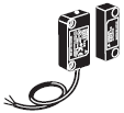 | Photocoupler outputs * | 2 m | D40Z-1C2 |
| 5 m | D40Z-1C5 |
Note: Must be used in combination with a G9SP Safety Controller or a G9SX-NS[] Non-contact Door Switch Controller.
*1. Photocoupler output. Load current: 10 mA
Controllers
Non-contact Door Switch Controller G9SX-NS[]
| Safety outputs *1 | Auxiliary monitoring output *3 | Logical AND con- nection input | Logical AND con- nection output | OFF- delayed Max. OFF- delay time *4 | Rated voltage | Terminal block type | Model | |
|---|---|---|---|---|---|---|---|---|
| Instanta- neous | OFF- delayed *2 | |||||||
| 2 (Semi- conductors) | 0 | 2 (Semi- conductors) | 1 | 1 | -- | 24 VDC | Screw terminals | G9SX-NS202-RT |
| Spring- cage terminals | G9SX-NS202-RC | |||||||
| 2 (Semi- conductors) | 3.0 s | Screw terminals | G9SX-NSA222-T03-RT | |||||
| Spring- cage terminals | G9SX-NSA222-T03-RC | |||||||
Note: For details, refer to the D40A/G9SX-NS Catalog (Cat. No. C140).
*1. P channel MOS FET transistor output
*2. The OFF-delayed output becomes an instantaneous output by setting the OFF-delay time to 0 s.
*3. PNP transistor output
*4. The OFF-delay time can be set in 16 steps as follows:
0/0.2/0.3/0.4/0.5/0.6/0.7/0.8/0.9/1.0/1.2/1.4/1.8/2.0/2.5/3.0 s
Safety Controller G9SP Series
| Name | No. of I/O points | Unit version | Model | |||
|---|---|---|---|---|---|---|
| Safety inputs | Test outputs | Safety outputs | Standard outputs | |||
| Safety Controller | 10 | 4 | Semiconductor outputs: 4 | 4 | Ver.2.0 | G9SP-N10S |
| 10 | 6 | Semiconductor outputs: 16 | -- | G9SP-N10D | ||
| 20 | 6 | Semiconductor outputs: 8 | -- | G9SP-N20S | ||
Note: For details, refer to the G9SP Catalog (Cat. No. F090).
last update: December 11, 2017
OMRON D40Z specification
D40Z Compact non-contact Door Switch/Specificationslast update: December 11, 2017
Ratings and Characteristics
| Model | D40Z-1C[] | |
|---|---|---|
| Interlock type | Type 4 (EN ISO 14119) | |
| Coding level | Low level coded (EN ISO 14119) | |
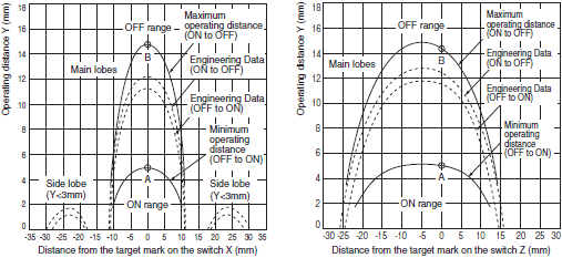
| Operating characteristics *2 | Operating distance (OFF --> ON) | 5 mm min. *1 |
| Operating distance (ON --> OFF) | 15 mm max. *1 | |
| Differential travel | 20% or less of operating distance at 23 °C (maximum 2.5 mm) | |
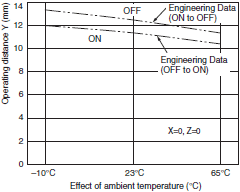
| Influence of temperature | 20% or less of operating distance at 23 °C within temperature range of -10 to 65 °C | |
| Repeat accuracy | ±10% of operating distance at 23 °C | |
| Ambient operating temperature | -10 to 65 °C (with no icing or condensation) | |
| Ambient operating humidity | 25% to 85% | |
| Insulation resistance (between charged parts and case) | 50 MΩ max. (at 500 VDC) | |
| Dielectric strength (between charged parts and case) | 1,000 VAC for 1 min | |
| Degree of contamination | 3 | |
| Electromagnetic compatibility | IEC/EN 60497-5-3 compliant | |
| Vibration resistance | 10 to 55 to 10 Hz (single amplitude: 0.75 mm, double amplitude: 1.5 mm) | |
| Shock resistance | 300 m/s2 min. | |
| Degree of protection | IP67 | |
| Material | PBT resin | |
| Mounting method | M4 screws | |
| Terminal screw tightening torque | 1 N·m | |
| Power supply voltage | 24 V DC +10%/-15% | |
| Power consumption *3 | 0.5 W max. | |
| Auxiliary monitoring output | Photocoupler output: 24 V DC, load current: 10 mA | |
| LED indicators | Actuator not detected (lights in red); error occurred (blinks in red), actuator detected (lights in yellow), actuator detected and Non-contact Door Switch input OFF (blinks in yellow) | |
| Connecting cables | 2 m, 5 m | |
| Number of connectable switches | 30 max. (wiring length: 100 m max.) *4 | |
| Weight | Switch: approx. 175 g, actuator: approx. 20 g (D40Z-1C5) | |
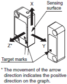
*1. The condition of this distance are that the switch and actuator target marks are on the same axis and the sensing
surfaces are exactly parallel condition. OFF to ON distance shows the switch approaching (Point A in the engineering
data graph) and ON to OFF distance shows the switch separating away (Point B in the engineering data graph).
*2. For details on response time and operating time, refer to the catalog or manual of a safety controller to be connected.
*3. Power to be provided to the load is not included.
*4. For details, refer to item "Precautions for Correct Use".
Engineering Data
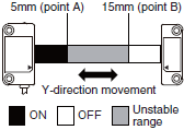
Note: 1. The operating distance is the distance between the switch and actuator sensing surfaces.
2. The graph of detection area indicates shifting to X or Z direction from following condition that the switch and
actuator target marks are on the same axis and the sensing surfaces are exactly parallel condition.
Dashed lines indate reference value for maximum and minimun oprating distance at abient temperature +23°C.
The solid line indicates reference values of the maximum and minimum operating distances.
3. The operating distance may be affected by ambient metal, magnet catches, and temperature.
4. Detection may occur other than on the detection surfaces of the switch and actuator. Before you use the switch and
actuator, refer to “Switch and Actuator Operation” on Data Sheet to set the detection surfaces of the switch and
actuator face to face.
Influence of ambient temperature
Detection area
last update: December 11, 2017
OMRON D40Z catalog
D40Z Compact non-contact Door Switch/Catalog- Catalog
- Manual
- CAD
English
Global Edition
| Catalog Name | Catalog Number [size] | Last Update | |
|---|---|---|---|
| | C145-E1-02 [1918KB] | Nov 01, 201820181101 | D40Z Catalog |
- NO. D40Z
- TYPE:Safety Door Switches Non-Contact Door Switches
 Copyright Statement
 - DATE:2021-06-09
- Associated products:
D4BL Guard Lock Safety-door Switch/Features D40A / G9SX-NS Compact Non-Contact Door Switch/Non-Contact Door Switch Controller/Features