
OMRON KM1Energy Conservation Support / Environment Measure Equipment/ Electric Power Monitoring Equipment/Smart Power Monitor
OMRON KM1 Energy Conservation Support / Environment Measure Equipment
OMRON KM1 Dimensions
/Images/l_3123-25-118965-198x198.jpglast update: September 12, 2013
Greater Visualization Enables More Energy Savings
The key to saving energy lies in knowing the breakdown of electric power.
As we enter times of even greater power shortages, overall monitoring of electric power alone starts to lose its effectiveness. The key to finding hidden wastes of electric power is to enhance the visibility of power consumption at the distribution panel breaker level. The KM1 can help you determine when, where, and how much electric power is being used to help reduce unnecessary power consumption.

The KM1 platform solves the work and cost issues to visualize power consumption across all distribution panels.
Previous Problems
Previously, measuring electric power for multiple circuits or systems required costly and difficult-to-install power sensors.

Measuring multiple circuits requires difficult installation and results in high costs.
With the KM1...
The KM1 solves both the time and cost issues even for multiple circuits and systems.

The KM1 provides a simple and smart solution to the issues encountered with traditional power sensors.
Simple and Smart: The KM1 Platform
Dual System Monitoring
Industry-first Dual System Monitoring
A single KM1 can perform measurements for mixed distribution panels with circuits for both air-conditioners and lighting equipment.

Measure up to 36 circuits.
Add CT Expansion Units for More Measurements
One Measurement Master Unit accepts up to 4 CT inputs, and a CT Expansion Unit accepts up to 8 CT inputs. (Up to four CT Expansion Units can be added.) This enables the measurement of up to 36 single-phase two-wire circuits.

Space-efficient Design and Reduced Wiring
Mounting Space Reduced to 1/4 That of Previous Models
With the KM1, all you need is five Power Monitors.
You can reduce the mounting space by 76%.

Linked design eliminates the need for voltage and communications wiring.
The elimination of communications and power line crossovers results in less time and work required for wiring.

Direct Measurement of 480 V without a VT
No VT equipment is required, even for 480 V measurements.

High-precision Measurements
High-precision Micropower Measurements
The KM1 performs high-precision measurement even below 5% of the rated current.
Even standby energy can be measured dependably.

Primary-side Inverter Support
The KM1 can provide accurate measurements without any current waveform distortion even after an inverter is installed. Measurement accuracy: ±2% FS This enables measuring the effectiveness of energy conservation measures after installation.

Additional Measurements to Aid in Energy Conservation
Visualization to Help Maintenance
With the wide range of output capabilities on the KM1, you can see exactly when you should perform maintenance.
● Overcurrent, Undercurrent, Overvoltage, and Undervoltage Alarm Output

Visualization of Specific Power Consumption through Pulse/Temperature Input Units
Use pulse inputs to measure production information at the same time, including flow rates, throughput, temperature inputs, and more. When this information is combined with other electric power data, you can easily visualize the specific power consumption.

* Input is performed with the KM1-EMU8A-FLK.
Visualization of Power Generation Effectiveness
The effectiveness of power generation can be visualized by measuring the power consumption and regenerative power together at the same time.

Energy Classification
The total power consumption and total time can be divided up between the three states of stopped, standby, and operating based on the power consumption value and pulse input. Classifying energy helps to clearly identify areas where improvement is possible.

* This function is supported only by the KM1-PMU[]A-FLK.
last update: September 12, 2013
Purchase the OMRON Smart Power Monitor Please fill in the following
If you have just landed here, this product OMRON KM1 Energy Conservation Support / Environment Measure Equipment,Energy Conservation Support / Environment Measure Equipment is offered online by Tianin FLD Technical Co.,Ltd. This is an online store providing Energy Conservation Support / Environment Measure Equipment at wholesale prices for consumers. You can call us or send enquiry, we would give you the prices, packing,deliverty and more detailed information on the KM1 We cooperate with DHL,TNT,FEDEX,UPS,EMS,etc.They guarantee to meet your needs in terms of time and money,even if you need your OMRON KM1Energy Conservation Support / Environment Measure Equipment tomorrow morning (aka overnight or next day air) on your desk, 2, 3 days or more.Note to international customers, YES, we ship worldwide.
E6D-C High-resolution Encoder with Diameter of 55 mm/Features
G2R-[]-S (S) General-purpose Relay/Features
E5CD / E5CD-B Digital Temperature Controller (48 x 48 mm)/Features
H3DK-F Twin Timer/Features
ZN-PD Air Particle Sensor/Features
OMRON KM1 dimension
KM1 Multi-circuit Smart Power Monitor/Dimensionslast update: November 06, 2013
Smart Power Monitors
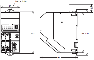
KM1-PMU1A-FLK/PMU2A-FLK/EMU8A-FLK/KE1-CTD8E
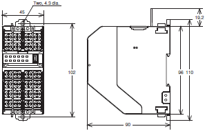
KE1-DRT-FLK
Separate Current Transformers (CTs)
KM20-CTF-5A
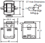
KM20-CTF-50A
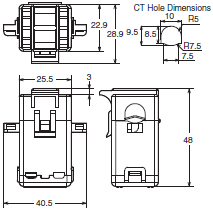
KM20-CTF-100A
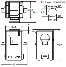
KM20-CTF-200A
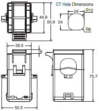
KM20-CTF-400A/600A
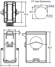
In-panel CT, penetration type
KM20-CTB-5A/50A
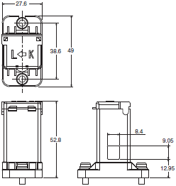
CT Cable
KM20-CTF-CB3 (Special CT cable)

last update: November 06, 2013
OMRON KM1 catalog
KM1 Multi-circuit Smart Power Monitor/Catalog- Catalog
- Manual
- CAD
English
Global Edition
| Catalog Name | Catalog Number [size] | Last Update | |
|---|---|---|---|
| | N170-E1-01 [4557KB] | Sep 24, 201520150924 | KM1 Catalog |
OMRON KM1 lineup
KM1 Multi-circuit Smart Power Monitor/Lineuplast update: September 12, 2013
Smart Power Monitors
| Model | Unit type | Unit category | Power supply voltage | Communications |
|---|---|---|---|---|
| KM1-PMU2A-FLK | Dual Power System Measurement Unit | Measurement master | 100 to 240 VAC | RS-485 |
| KM1-PMU1A-FLK | Power Measurement Unit | |||
| KM1-EMU8A-FLK | Pulse/Temperature Input Unit | Function slave | ||
| KE1-CTD8E | CT Extension Unit | CT extension slave | Power supplied from the Measurement Master Unit | - |
| KE1-DRT-FLK | DeviceNet Communications Unit | Communications slave | 100 to 240 VAC | RS-485 or DeviceNet |
Options (Order Separately)
Separate or In-panel Current Transformer (CT)
| Model | Rated primary current | Rated secondary current | Installation |
|---|---|---|---|
| KM20-CTF-5A | 5 A | Special output | Installed separately |
| KM20-CTF-50A | 50 A | ||
| KM20-CTF-100A | 100 A | ||
| KM20-CTF-200A | 200 A | ||
| KM20-CTF-400A | 400 A | ||
| KM20-CTF-600A | 600 A | ||
| KM20-CTB-5A/50A | 5 A/50 A | In-panel (penetration type) |
Note: CT Cables are not included with the CTs.
Current Transformer (CT) Cable
| Model | Specification |
|---|---|
| KM20-CTF-CB3 | 3-m cable |
Note: Use the CT Cable specified by OMRON or one manufactured by JST Mfg. Co.
You can also use a 1.25-B3A crimping terminal or AWG22 power cable.
Related Devices (Sold Separately)
When Connected to a Computer
Communications Interface Converter
| Model | Rated primary current | Rated secondary current | Installation |
|---|---|---|---|
| K3SC-10 AC100-240 | 30 × 80 × 78 (W×H×D) | RS-232C, USB <-> Half-duplex RS-485 | 100 to 240 VAC |
| K3SC-10 AC/DC24 | 24 VAC/DC |
last update: September 12, 2013
OMRON KM1 specification
KM1 Multi-circuit Smart Power Monitor/Specificationslast update: October 01, 2015
Ratings
| Model | Master Unit | Slave Unit | |||
|---|---|---|---|---|---|
| KM1-PMU2A-FLK (Dual Power Systems) | KM1-PMU1A-FLK (Single Power System) | KM1-EMU8A-FLK (Pulses/ Temperatures) | KE1-CTD8E (CT Extension Unit) | ||
| Applicable phase wiring method | Single-phase two- wire, single-phase threewire, and three-phase three- wire | Single-phase two- wire, single-phase three-wire, three- phase three-wire, and three-phase four-wire | - | Single-phase two- wire, single-phase three-wire, three- phase three-wire, and three-phase four-wire | |
| Maximum number of CT connections | 4 | 3 | - | 8 | |
| Selectable types of CT capacities | 2 types | 1 type | - | Two types per Slave Unit | |
| Power supply | Rated power supply voltage | 100 to 240 VAC, 50/60 Hz | - | ||
| Allowable supply voltage range | 85% to 110% of rated power supply voltage | - | |||
| Power supply allowable frequency range | 45 to 65 Hz | - | |||
| Power consumption | Standalone: 10 VA max., Maximum expansion: 14 VA max. | 10 VA max. | - | ||
| Input | Rated input voltage | 100 to 480 VAC (single-phase, 2- wire): Line voltage 100/200 VAC (single-phase, 3- wire): Phase voltage/line voltage 100 to 480 VAC (3-phase, 3-wire): Line voltage | 100 to 480 VAC (single-phase, 2- wire): Line voltage 100/200 VAC (single-phase, 3-wire): Phase voltage/line voltage 100 to 480 VAC (3-phase, 3-wire): Line voltage 58 to 277 VAC (3-phase, 4-wire): Phase voltage | - | |
| Rated input current (CT) | (5, 50, 100, 200, 400, or 600 A) | - | (5, 50, 100, 200, 400, or 600 A) | ||
| Rated input power | With 5-A CT: 4 kW With 50-A CT: 40 kW With 100-A CT: 80 kW With 200-A CT: 160 kW With 400-A CT: 320 kW With 600-A CT: 480 kW | - | |||
| Rated input frequency | 50/60 Hz | - | |||
| Allowable input frequency range | 45 to 65 Hz | - | |||
| Allowable input voltage | 110% of rated input voltage (continuous) | - | |||
| Allowable input current | 120% of rated input current (continuous) | - | 120% of rated input current (continuous) | ||
| Rated input load | Voltage input: 0.5 VA max. (excluding power supply) Current input: 0.5 VA max. (for each input) | - | Current input: 0.5 VA max. (for each input) | ||
| Clock | Clock setting | 2012 to 2099 (Adjusted for leap years during this period.) | - | ||
| Clock accuracy | ±1.5 min./month (at 23°C) | - | |||
| Clock backup period | Seven-day backup with an electric double-layer capacitor (after being powered for at least 24 hours and when at 23°C when the power is turned OFF) | - | |||
| Ambient operating temperature | -10 to 55°C (with no condensation or icing) | ||||
| Storage humidity | -25 to 65°C (with no condensation or icing) | ||||
| Ambient operating humidity | 25% to 85% | ||||
| Storage humidity | 25% to 85% | ||||
| Altitude | 2,000 m max. | ||||
| Installation environment | Overvoltage category II, pollution degree 2, measurement category II | ||||
| Compliant standards | EN/IEC 61010-2-030 and EN/IEC 31626-1 Industrial electromagnetic environment | ||||
Performance
| Model | Master Unit | Slave Unit | |||
|---|---|---|---|---|---|
| KM1-PMU2A-FLK (Dual Power Systems) | KM1-PMU1A-FLK (Single Power System) | KM1-EMU8A-FLK (Pulses/ Temperatures) | KE1-CTD8E (CT Extension Unit) | ||
| Accu- racy *1 | Voltage | ±1.0% FS, ±1 digit; or, ±2.0% FS, ±1 digit for voltage across Vtr under the same conditions | - | ||
| Current | ±1.0% FS, ±1 digit However, the accuracy is ±2.0% FS, ±1 digit for the phase-S current for a three- phase, three-wire circuit and the phase- N current for a singlephase, three-wire circuit under the same conditions. | - | ±1.0% FS, ±1 digit | ||
| However, the accuracy is ±2.0% FS, ±1 digit for the phase-S current for a three-phase, three-wire circuit and the phase-N current for a single-phase, three- wire circuit under the same conditions. | |||||
| Power (active power and reactive power) | Active power and reactive power ±2.0% FS, ±1 digit (Power factor = 1) | - | Active power and reactive power ±2.0% FS, ±1 digit (Power factor = 1) | ||
| Frequency | ±0.3 Hz ±1 digit | - | |||
| Power factor *2 | ±5.0% FS at an ambient temperature of 23°C, rated input, rated frequency, and a power factor of 0.5 to 1 to 0.5 | - | ±5.0% FS at an ambient temperature of 23°C, rated input, rated frequency, and a power factor of 0.5 to 1 to 0.5 | ||
| Temperature | - | ±5°C two hours after the power supply is turned ON (after performing any adjustments for the ambient temperature) | - | ||
| Temperature infl uence | ±1.0% FS (percentage of the measurement value at an ambient temperature of 23°C, rated input, rated frequency, and a power factor of 1 in the operating temperature range) | ±1.0% FS (percentage of the measurement value at an ambient temperature of 23°C in the operating temperature range) | ±1.0% FS (percentage of the measurement value at an ambient temperature of 23°C, rated input, rated frequency, and a power factor of 1 in the operating temperature range) | ||
| Infl uence of frequency | ±1.0% FS (percentage of the measurement value at an ambient temperature of 23°C, rated input, rated frequency, and a power factor of 1 in the rated frequency ±5 Hz range) | - | ±1.0% FS (percentage of the measurement value at an ambient temperature of 23°C, rated input, rated frequency, and a power factor of 1 in the rated frequency ±5 Hz range) | ||
| Infl uence of harmonics | ±0.5% FS (at ambient temperature of 23°C, error for superimposed 2nd, 3rd, 5th, 7th, 9th, 11th, and 13th harmonics for a content percentage of 30% for current and 5% for voltage of the basic wave) | - | ±0.5% FS (at ambient temperature of 23°C, error for superimposed 2nd, 3rd, 5th, 7th, 9th, 11th, and 13th harmonics for a content percentage of 30% for current and 5% for voltage of the basic wave) | ||
| Low-cut current set value | 0.1% to 19.9% of rated input in 0.1% increments | - | 0.1% to 19.9% of rated input in 0.1% increments | ||
| Sampling cycle | 100 ms for measurement voltage at 50 Hz and 83.3 ms for measurement voltage at 60 Hz | 100 ms | 100 ms for measurement voltage at 50 Hz and 83.3 ms for measurement voltage at 60 Hz | ||
| Insulation resistance | Insulation resistance: 20 M (at 500 VDC) | ||||
| Dielectric strength | All models: Locations to which 2,000 V was applied for one minute: Between all terminals and case KM1-PMU1A-FLK: Between the power supply terminals and RS-485/USB/transistor output Between the power supply terminals and current/voltage input Between current/voltage input and RS-485/USB/transistor outputs KM1-PMU2A-FLK: Between the power supply terminals and RS-485/USB/transistor outputs Between the power supply terminals and current/voltage input Between current/voltage inputs and RS-485/USB/transistor outputs Between current/voltage input 1 and voltage input 2 KM1-EMU8A-FLK: Between power supply terminals, temperature input, and RS-485/USB/transistor outputs KE1-CTD8E: Between current inputs and USB/relay outputs | ||||
| Vibration resistance | Single-amplitude: 0.35 mm, Acceleration: 50 m/s2 Vibration: 10 to 55 Hz, 10 sweeps of 5 minutes each along 3 axes | ||||
| Shock resistance | 150 m/s2, 3 times each in 6 directions (up/down, left/right, forward/backward) | ||||
| Weight | 230 g | ||||
| Memory backup | No. of writes to non-volatile memory: 1,000,000 times | ||||
| Event inputs | Number of inputs | - | 7 | - | |
| No-voltage inputs | - | ON current: 15 mA max., ON residual voltage: 8 V max., OFF leakage current: 1.5 mA max. | - | ||
| Voltage input | - | High level: 4.75 to 30 VDC Low level: 0 to 2 VDC Input impedance: Approx. 2 kΩ | - | ||
| Minimum input time | - | 5ms | - | ||
| Tem- perature inputs | Thermisto inputs | - | 1 | - | |
| Applicable thermistor | - | E52-THE5A Color code (blue): -50 to 50°C Color code (black): 0 to 100°C | - | ||
| Combinations | Capable of supporting 7 event inputs and 1 temperature input when linked with the KM1-EMU8A-FLK. | - | |||
| Tran- sistor outputs | Number of outputs | Three open collectors (OUT1, OUT2, OUT3) and common | - | ||
| Output capacity | 30 VDC, 30 mA | - | |||
| ON residual voltage | 1.2 V max. | - | |||
| OFF leakage current | 100 μA max. | - | |||
| Total power consumption pulse output | Outputs one pulse when the power consumption reaches the set pulse output unit (1, 10, 100, 1k, 2k, 5k, 10k, 20k, 50k, 100k W/h). | - | |||
| Alarm output | Outputs an alarm based on the set alarm output threshold. | - | |||
| Recovery method | Automatic recovery only | - | |||
| Relay output | Number of outputs | - | One NO contact (OUT1) | ||
| Rated load | - | Resistance load, 125 VAC, 3 A; 30 VDC, 3 A | |||
| Mechanical life expectancy | - | 5,000,000 times min. | |||
| Electrical life expectancy | - | 200,000 times min. (rated load switching frequency: 1,800 times/h) | |||
| Failure rate P level | - | 5 VDC, 10 mA (at a switching frequency of 120 times/min) | |||
| Alarm output | - | Turns output ON or OFF based on the alarm set value. | |||
| Recovery method | - | Automatic recovery only | |||
| RS-485 | Protocols | Communications protocol setting: Compoway/F or Modbus | |||
| Sync method | Start-stop | ||||
| Node number setting | CompoWay/F: 0 to 99, Modbus:1 to 99 When a switch operation is performed to set the protocol to Modbus when the node number is set to 0, the node number is automatically changed to 1. | ||||
| Baud rate | 9,600 bps, 19,200 bps, or 38,400 bps | ||||
| Transmission code | CompoWay/F: ASCII, Modbus: Binary | ||||
| Data length *3 | CompoWay/F: 7 bits, 8 bits; Modbus: 8 bits | ||||
| Stop bits *3 | CompoWay/F: 1 bits or 2 bits; Modbus: 1 bit with priority, 2 bits without priority | ||||
| Parity | Even, odd, or none | ||||
| Maximum transmission distance | 500 m | ||||
| Maximum number of nodes | CompoWay/F: 31, Modbus: 99 | ||||
| Communication items | Refer to the relevant communications specifi cations manuals. | ||||
| USB | USB 1.1 compatible | ||||
| Memory retention for power interruptions | Parameter data Total power consumption (Saved to internal memory every 5 minutes.) | ||||
| Number of link connector insertions/removals | 25 times | ||||
*1. Based on JISC1111, without special CT error, at ambient temperature of 23° C, rated input, and rated frequency.
Applicable to 2nd, 3rd, 5th, 7th, 9th, 11th, and 13th harmonics.
*2. Power factor formula: Power factor = Active power/Apparent power

*3. The set value may change when the protocol is changed to Modbus. Check the set values if you change the DIP
switch settings.
Special CTs
Current Transformer (CT) Cable
| Confi guration | Installed separately | In-panel (penetration type) | |||||
|---|---|---|---|---|---|---|---|
| Model | KM20- CTF-5A | KM20- CTF-50A | KM20- CTF-100A | KM20- CTF-200A | KM20- CTF-400A | KM20- CTF-600A | KM20-CTB- 5A/50A |
| Rated primary current | 5 A | 50 A | 100 A | 200 A | 400 A | 600 A | 5 A/50 A |
| Rated secondary current | 1.67 mA | 1.67 mA | 33.3 mA | 66.7 mA | 66.7 mA | 66.7 mA | 1.67 mA/ 16.7 mA |
| Secondary winding | 3,000 turns | 6,000 turns | 9,000 turns | 3,000 turns | |||
| Applicable frequency | 10 Hz to 5 kHz | ||||||
| Insulation resistance | Between output terminals and case: 50 MΩ min. (at 500 VDC) | ||||||
| Dielectric strength | Between output terminals and case: 2,000 VAC for 1 minute | ||||||
| Protective element | 7.5-V clamp element | ||||||
| Allowable number of connections/ disconnections | 100 times | ||||||
| Applicable wire diameter * | 7.9 mm max. | 9.5 mm max. | 14.5 mm max. | 24.0 mm max. | 35.5 mm max. | 8.4 mm max. | |
| Operating temperature and humidity ranges | -20 to 60°C, 85% max. (with no condensation) | ||||||
| Storage temperature and humidity ranges | -30 to 65°C, 85% max. (with no condensation) | ||||||
Note: Operate the Special CTs at a low voltage of 600 V or less.
* If you use a fl at cable, select the cable based on the dimensions of the CT.
Current Transformer (CT) Cable
| Model | KM20-CTF-CB3 |
|---|---|
| Cable length | 3 m |
Note: Either use the CT Cable specifi ed by OMRON or use 1.25-B3A crimp terminals and AWG22 wire from J.S.T. Mfg. Co., Ltd.
Specifications
DeviceNet Communications Unit (KE1-DRT-FLK)
DeviceNet Communications Specifications
| Item | Specification | |||
|---|---|---|---|---|
| Communications | Remote I/O communications (I/O assignment settings with simple assignment settings or the Configurator) Message communications | |||
| Connection configuration | Can be a combination of multidrops and T-branching (for both main and branch lines). | |||
| Baud rate | 500, 250, or 125 kbps (automatically detected) | |||
| Rated primary current | 5 dedicated lines (2 signal lines, 2 power lines, and 1 shield) | |||
| Communications distance | Baud rate | Maximum network length | Branch line length | Total for all branch lines |
| 500 kbps | 100 m max. (100 m max.) | 6 m max. | 39 m max. | |
| 250 kbps | 250 m max. (100 m max.) | 6 m max. | 78 m max. | |
| 125 kbps | 500 m max. (100 m max.) | 6 m max. | 156 m max. | |
| Numbers in parentheses are the lengths for thin cable. | ||||
last update: October 01, 2015
- NO. KM1
- TYPE:Electric Power Monitoring Equipment Smart Power Monitor
 Copyright Statement
 - DATE:2021-06-12
- Associated products:
KM-N2-FLK Power Monitor/Features KM50-E Smart Power Monitor/Features