
OMRON NX-PD / PF / PC / TBXAutomation Systems/ Machine Automation Controllers/NX-series I/O System
OMRON NX-PD / PF / PC / TBX Automation Systems
OMRON NX-PD / PF / PC / TBX Dimensions
/Images/l_3193-25-171944-198x198.jpglast update: October 11, 2016
• Units to feed in additional Unit power and I/O power to an NX-series remote I/O terminal.
• Screwless clamp terminal block significantly reduces wiring work.
• Space-saving 12 mm wide units.
• The NX Unit Power Supply Unit allows expansion of the I/O configuration beyond the maximum power supply capacity of the EtherCAT Coupler
• The I/O Power Supply Unit is used when the total allowed I/O current per feed terminal is exceeded, or to split I/O power into groups.
• The I/O Power Connection Unit can be used as an additional power supply terminal for connected sensors and actuators.
• The FG Terminal Expansion Unit can be used as ground terminal for wire shields.
• The screwless terminal block is detachable for easy commissioning and maintenance.
Sysmac is a trademark or registered trademark of OMRON Corporation in Japan and other countries for OMRON factory automation products.
EtherCAT® is a registered trademark of Beckhoff Automation GmbH for their patented technology. EtherNet/IPTM is the trademarks of ODVA.
Other company names and product names in this document are the trademarks or registered trademarks of their respective companies.
last update: October 11, 2016
Purchase the OMRON NX-series I/O System Please fill in the following
If you have just landed here, this product OMRON NX-PD / PF / PC / TBX Automation Systems,Automation Systems is offered online by Tianin FLD Technical Co.,Ltd. This is an online store providing Automation Systems at wholesale prices for consumers. You can call us or send enquiry, we would give you the prices, packing,deliverty and more detailed information on the NX-PD / PF / PC / TBX We cooperate with DHL,TNT,FEDEX,UPS,EMS,etc.They guarantee to meet your needs in terms of time and money,even if you need your OMRON NX-PD / PF / PC / TBXAutomation Systems tomorrow morning (aka overnight or next day air) on your desk, 2, 3 days or more.Note to international customers, YES, we ship worldwide.
ZS Series Smart Sensors 2D CMOS Laser Type/Features
E2A3 Cylindrical Proximity Sensor/Features
61F-GPN-BT / -BC Conductive Level Controller/Features
E5CSV Temperature Controllers/Features
H7CN Solid-state Counter/Features
OMRON NX-PD / PF / PC / TBX lineup
NX-PD / PF / PC / TBX NX-series System Unit/Lineuplast update: August 1, 2018
SYSTEM Units
| Product name | Specifications | Model |
|---|---|---|
| Additional NX Unit Power Supply Unit  | Power supply voltage: 24 VDC (20.4 to 28.8 VDC) NX Bus power supply capacity: 10 W max. | NX-PD1000 |
| Additional I/O Power Supply Unit  | Power supply voltage: 5 to 24 VDC (4.5 to 28.8 VDC) I/O power feed maximum current: 4 A | NX-PF0630 |
| Power supply voltage: 5 to 24 VDC (4.5 to 28.8 VDC) I/O power feed maximum current: 10 A | NX-PF0730 | |
| I/O Power Supply Connection Unit  | Number of I/O power terminals: IOG: 16 terminals Current capacity of I/O power terminal: 4 A/terminal max. | NX-PC0010 |
| Number of I/O power terminals: IOV: 16 terminals Current capacity of I/O power terminal: 4 A/terminal max. | NX-PC0020 | |
| Number of I/O power terminals: IOV: 8 terminals, IOG: 8 terminals Current capacity of I/O power terminal: 4 A/terminal max | NX-PC0030 | |
| Shield Connection Unit  | Number of shield terminals: 14 terminals (The lower two terminals are functional ground terminals.) | NX-TBX01 |
Optional Products
| Product Name | Specification | Model |
|---|---|---|
| Unit/Terminal Block Coding Pins | For 10 Units (Terminal Block: 30 pins, Unit: 30 pins) | NX-AUX02 |
| Product Name | Specification | Model | |||
|---|---|---|---|---|---|
| No. of terminals | Terminal number indications | Ground terminal mark | Terminal current capacity | ||
| Terminal Block | 8 | A/B | None | 10 A | NX-TBA082 |
| Provided | NX-TBC082 | ||||
| 16 | None | NX-TBA162 | |||
| Provided | NX-TBC162 | ||||
Accessories
There are no accessories.
last update: August 1, 2018
OMRON NX-PD / PF / PC / TBX dimension
NX-PD / PF / PC / TBX NX-series System Unit/Dimensionslast update: January 15, 2018
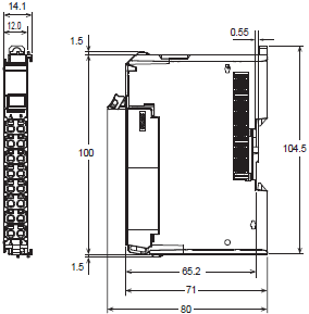
(Unit: mm)
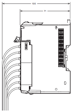
Additional NX Unit Power Supply Unit, Additional I/O Power Supply Unit, I/O Power Supply Connection Unit, and Shield Connection Unit
NX-PD1000/NX-PF0[]30/NX-PC00[]0/NX-TBX01
Unit Only
With Cables Connected
last update: January 15, 2018
OMRON NX-PD / PF / PC / TBX specification
NX-PD / PF / PC / TBX NX-series System Unit/Specificationslast update: August 1, 2018
General Specification
| Item | Specification | |
|---|---|---|
| Enclosure | Mounted in a panel | |
| Grounding method | Ground to 100 Ω or less | |
| Operating environment | Ambient operating temperature | 0 to 55°C |
| Ambient operating humidity | 10% to 95% (with no condensation or icing) | |
| Atmosphere | Must be free from corrosive gases. | |
| Ambient storage temperature | -25 to 70°C (with no condensation or icing) | |
| Altitude | 2,000 m max. | |
| Pollution degree | 2 or less: Conforms to JIS B3502 and IEC 61131-2. | |
| Noise immunity | 2 kV on power supply line (Conforms to IEC61000-4-4.) | |
| Overvoltage category | Category II: Conforms to JIS B3502 and IEC 61131-2. | |
| EMC immunity level | Zone B | |
| Vibration resistance | Conforms to IEC 60068-2-6. 5 to 8.4 Hz with 3.5-mm amplitude, 8.4 to 150 Hz, acceleration of 9.8 m/s2, 100 min each in X, Y, and Z directions (10 sweeps of 10 min each = 100 min total) | |
| Shock resistance | Conforms to IEC 60068-2-27. 147 m/s2, 3 times each in X, Y, and Z directions | |
| Applicable standards * | cULus: Listed (UL508), ANSI/ISA 12.12.01, EU: EN 61131-2, C-Tick or RCM, KC Registration, NK, and LR | |
* Refer to the OMRON website (www.ia.omron.com) or ask your OMRON representative for the most recent applicable standards for each model.
Specification
Additional NX Unit Power Supply Unit NX-PD1000
| Unit name | Additional NX Unit Power Supply Unit |
|---|---|
| Model | NX-PD1000 |
| External connection terminals | Screwless push-in terminal block (8 terminals) |
| Power supply voltage | 24 VDC (20.4 to 28.8 VDC) |
| NX Bus power supply capacity | 10 W max. (Refer to Installation orientation and restrictions for details.) |
| NX Unit power supply efficiency | 70% |
| Unwired terminal current capacity | 4 A max. (Including the current of through-wiring) |
| Dimensions | 12 (W) × 100 (H) 71 × (D) |
| Isolation method | No-isolation |
| Insulation resistance | 20 MΩ min. between isolated circuits (at 100 VDC) |
| Dielectric strength | 510 VAC between isolated circuits for 1 minute at a leakage current of 5 mA max. |
| NX Unit power consumption | • Connected to a CPU Unit or Communication Control Unit 0.85 W max. • Connected to a Communications Coupler Unit 0.45 W max. |
| I/O current consumption | No consumption |
| Weight | 65g max. |
| Circuit layout | 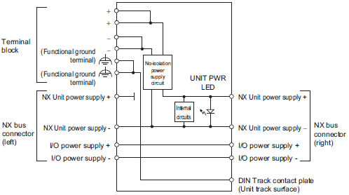 |
| Installation orientation and restrictions | 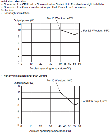 |
| Terminal connection diagram | 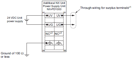 |
*1. You can use the unwired terminals of the Unit power supply terminals (UV/UG) for through-wiring of the Additional NX
Unit Power Supply Unit or the Unit power supply terminals on the EtherCAT Coupler Unit.
*2. The NC terminal is not connected to the internal circuit.
Additional I/O Power Supply Units NX-PF0[]30
| Unit name | Additional I/O Power Supply Unit | |
|---|---|---|
| Model | NX-PF0630 | NX-PF0730 |
| External connection terminals | Screwless push-in terminal block (8 terminals) | |
| Power supply voltage | 5 to 24 VDC (4.5 to 28.8 VDC) * | |
| I/O power supply maximum current | 4 A | 10 A |
| Current capacity of I/O power supply terminal | 4 A max. | 10 A max. |
| Dimensions | 12 (W) × 100 (H) 71 × (D) | |
| Isolation method | No-isolation | |
| Insulation resistance | 20 MΩ min. between isolated circuits (at 100 VDC) | |
| Dielectric strength | 510 VAC between isolated circuits for 1 minute at a leakage current of 5 mA max. | |
| NX Unit power consumption | • Connected to a CPU Unit or Communication Control Unit 0.85 W max. • Connected to a Communications Coupler Unit 0.45 W max. | |
| I/O current consumption | 10 mA max. | |
| Weight | 65 g max. | |
| Circuit layout | 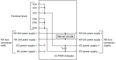 | |
| Installation orientation and restrictions | Installation orientation: • Connected to a CPU Unit or Communication Control Unit: Possible in upright installation. • Connected to a Communications Coupler Unit: Possible in 6 orientations. Restrictions: No restrictions | |
| Terminal connection diagram |  | |
| Overload/low voltage detection | Not supported | |
| Protective function | Not supported. | |
* Use an output voltage that is appropriate for the I/O circuits of the NX Units and the connected external devices.
I/O Power Supply Connection Unit IOG terminal type NX-PC0010
| Unit name | I/O Power Supply Connection Unit |
|---|---|
| Model | NX-PC0010 |
| External connection terminals | Screwless push-in terminal block (16 terminals) |
| Number of I/O power supply terminals | IOG: 16 terminals |
| Current capacity of I/O power supply terminal | 4 A/terminal max. |
| Dimensions | 12 (W) × 100 (H) 71 ×(D) |
| Isolation method | No-isolation |
| Insulation resistance | 20 MΩ min. between isolated circuits (at 100 VDC) |
| Dielectric strength | 510 VAC between isolated circuits for 1 minute at a leakage current of 5 mA max. |
| NX Unit power consumption | • Connected to a CPU Unit or Communication Control Unit 0.85 W max. • Connected to a Communications Coupler Unit 0.45 W max. |
| I/O current consumption | No consumption |
| Weight | 65 g max. |
| Circuit layout | 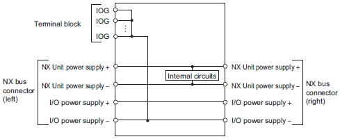 |
| Installation orientation and restrictions | Installation orientation: • Connected to a CPU Unit or Communication Control Unit: Possible in upright installation. • Connected to a Communications Coupler Unit: Possible in 6 orientations. Restrictions: No restrictions |
| Terminal connection diagram | 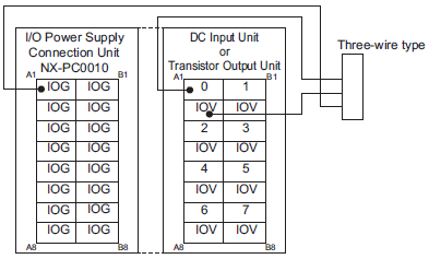 |
I/O Power Supply Connection Unit IOV terminal type NX-PC0020
| Unit name | I/O Power Supply Connection Unit |
|---|---|
| Model | NX-PC0020 |
| External connection terminals | Screwless push-in terminal block (16 terminals) |
| Number of I/O power supply terminals | IOV: 16 terminals |
| Current capacity of I/O power supply terminal | 4 A/terminal max. |
| Dimensions | 12 (W) × 100 (H) 71 × (D) |
| Isolation method | No-isolation |
| Isolation resistance | 20 MΩ min. between isolated circuits (at 100 VDC) |
| Dielectric strength | 510 VAC between isolated circuits for 1 minute at a leakage current of 5 mA max. |
| NX Unit power consumption | • Connected to a CPU Unit or Communication Control Unit 0.85 W max. • Connected to a Communications Coupler Unit 0.45 W max. |
| I/O current consumption | No consumption |
| Weight | 65 g max. |
| Circuit layout | 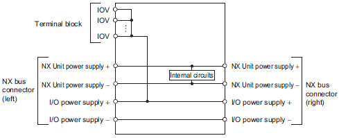 |
| Installation orientation and restrictions | Installation orientation: • Connected to a CPU Unit or Communication Control Unit: Possible in upright installation. • Connected to a Communications Coupler Unit: Possible in 6 orientations. Restrictions: No restrictions |
| Terminal connection diagram | 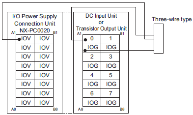 |
I/O Power Supply Connection Unit IOV/IOG terminal type NX-PC0030
| Unit name | I/O Power Supply Connection Unit |
|---|---|
| Model | NX-PC0030 |
| External connection terminals | Screwless push-in terminal block (16 terminals) |
| Number of I/O power supply terminals | IOV: 8 terminals IOG: 8 terminals |
| Current capacity of I/O power supply terminal | 4 A/terminal max. |
| Dimensions | 12 (W) × 100 (H) 71 × (D) |
| Isolation method | No-isolation |
| Insulation resistance | 20 MΩ min. between isolated circuits (at 100 VDC) |
| Dielectric strength | 510 VAC between isolated circuits for 1 minute at a leakage current of 5 mA max. |
| NX Unit power consumption | • Connected to a CPU Unit or Communication Control Unit 0.85 W max. • Connected to a Communications Coupler Unit 0.45 W max. |
| I/O current consumption | No consumption |
| Weight | 65 g max. |
| Circuit layout | 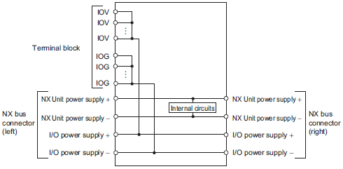 |
| Installation orientation and restrictions | Installation orientation: • Connected to a CPU Unit or Communication Control Unit: Possible in upright installation. • Connected to a Communications Coupler Unit: Possible in 6 orientations. Restrictions: No restrictions |
| Terminal connection diagram | 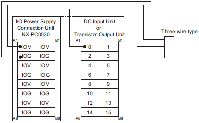 |
Shield Connection Unit NX-TBX01
| Unit name | Shield Connection Unit |
|---|---|
| Model | NX-TBX01 |
| External connection terminals | Screwless push-in terminal block (16 terminals) |
| Number of shield terminals | 14 terminals (The following two terminals are functional ground terminals.) |
| Dimensions | 12 (W) × 100 (H) 71 × (D) |
| Isolation method | Isolation between the SHLD functional ground terminal, and internal circuit: No-isolation |
| Insulation resistance | 20 MΩ min. between isolated circuits (at 100 VDC) |
| Dielectric strength | 510 VAC between isolated circuits for 1 minute at a leakage current of 5 mA max. |
| NX Unit power consumption | • Connected to a CPU Unit or Communication Control Unit 0.85 W max. • Connected to a Communications Coupler Unit 0.45 W max. |
| I/O current consumption | No consumption |
| Weight | 65 g max. |
| Circuit layout | 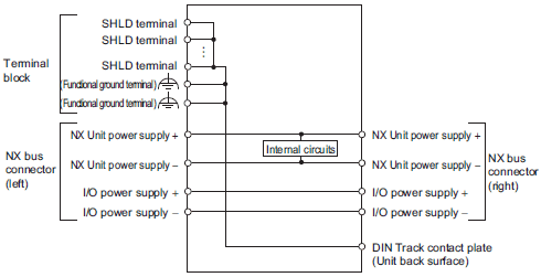 |
| Installation orientation and restrictions | Installation orientation: • Connected to a CPU Unit or Communication Control Unit: Possible in upright installation. • Connected to a Communications Coupler Unit: Possible in 6 orientations. Restrictions: No restrictions |
| Terminal connection diagram | 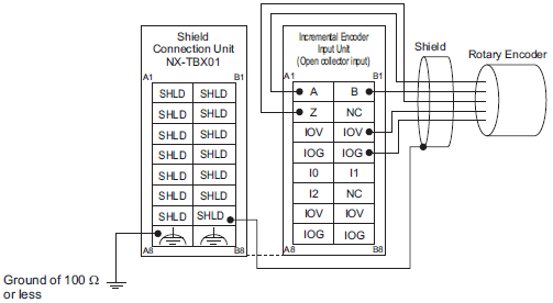 |
Version Information
Connecting with CPU Units
Refer to the user's manual for the CPU Unit for the models of CPU Unit to which NX Units can be connected.
| NX Unit | Corresponding unit versions/versions | ||
|---|---|---|---|
| Model | Unit Version | CPU Unit | Sysmac Studio |
| NX-PD1000 | Ver.1.0 | Ver.1.13 | Ver.1.17 |
| NX-PF0630 | |||
| NX-PF0730 | |||
| NX-PC0020 | |||
| NX-PC0010 | |||
| NX-PC0030 | |||
| NX-TBX01 | |||
Note: Some Units do not have all of the versions given in the above table. If a Unit does not have the specified version, support is provided by the oldest available version after the specified version. Refer to the user's manuals for the specific Units for the relation between models and versions.
Connecting with EtherCAT Coupler Units
| NX Unit | Corresponding unit versions/versions | |||
|---|---|---|---|---|
| Model | Unit Version | EtherCAT Coupler Unit | CPU Units or Industrial PCs | Sysmac Studio |
| NX-PD1000 | Ver.1.0 | Ver.1.0 | Ver.1.05 | Ver.1.06 |
| NX-PF0630 | ||||
| NX-PF0730 | Ver.1.08 | |||
| NX-PC0020 | Ver.1.06 | |||
| NX-PC0010 | ||||
| NX-PC0030 | ||||
| NX-TBX01 | ||||
Note: Some Units do not have all of the versions given in the above table. If a Unit does not have the specified version, support is provided by the oldest available version after the specified version. Refer to the user’s manuals for the specific Units for the relation between models and versions.
Connecting with EtherNet/IP Coupler Unit
| NX Unit | Corresponding unit versions/versions | ||||||
|---|---|---|---|---|---|---|---|
| Model | Unit Version | Application with an NJ/NX/NY-series Controller *1 | Application with a CS/CJ/CP-series PLC *2 | ||||
| EtherNet/IP Coupler Unit | CPU Unit or Industrial PC | Sysmac Studio | EtherNet/IP Coupler Unit | Sysmac Studio | NX-IO Configurator *3 | ||
| NX-PD1000 | Ver.1.0 | Ver. 1.2 | Ver. 1.14 | Ver. 1.19 | Ver.1.0 | Ver.1.0 | Ver. 1.00 |
| NX-PF0630 | |||||||
| NX-PF0730 | |||||||
| NX-PC0020 | |||||||
| NX-PC0010 | |||||||
| NX-PC0030 | |||||||
| NX-TBX01 | |||||||
Note: Some Units do not have all of the versions given in the above table. If a Unit does not have the specified version, support is provided by the oldest available version after the specified version. Refer to the user’s manuals for the specific Units for the relation between models and versions.
*1. Refer to the user’s manual for the EtherNet/IP Coupler Units for information on the unit versions of EtherNet/IP Units that are compatible with EtherNet/IP Coupler Units.
*2. Refer to the user’s manual for the EtherNet/IP Coupler Units for information on the unit versions of CPU Units and EtherNet/IP Units that are compatible with EtherNet/IP Coupler Units.
*3. For connection to an EtherNet/IP Coupler Unit with unit version 1.0, You can connect only to the peripheral USB port on the EtherNet/IP Coupler Unit. You cannot connect with any other path. If you need to connect by another path, use an EtherNet/IP Coupler Unit with unit version 1.2 or later.
Connecting with Communication Control Units
| NX Unit | Corresponding unit versions/versions | ||
|---|---|---|---|
| Model | Unit Version | Communication Control Unit | Sysmac Studio |
| NX-PD1000 | Ver.1.0 | Ver.1.00 | Ver.1.24 |
| NX-PF0630 | |||
| NX-PF0730 | |||
| NX-PC0020 | |||
| NX-PC0010 | |||
| NX-PC0030 | |||
| NX-TBX01 | |||
Note: Some Units do not have all of the versions given in the above table. If a Unit does not have the specified version, support is provided by the oldest available version after the specified version. Refer to the user’s manuals for the specific Units for the relation between models and versions.
last update: August 1, 2018
OMRON NX-PD / PF / PC / TBX catalog
NX-PD / PF / PC / TBX NX-series System Unit/Catalog- Catalog
- Manual
- CAD
English
Global Edition
| Catalog Name | Catalog Number [size] | Last Update | |
|---|---|---|---|
| | - [3361KB] | Aug 01, 201820180801 | NX-PD/PF/PC/TBX Data Sheet |
| | R183-E1-09 [6683KB] | Nov 01, 201820181101 | NX-series I/O System Catalog |
- NO. NX-PD / PF / PC / TBX
- TYPE:Machine Automation Controllers NX-series I/O System System Unit
- DATE:2021-06-10
- Associated products:
NX-CIF NX-series Communications Interface Units/Features NJ NJ Overview/Features