OMRON 61F-GPN-BT / -BCSwitches/ Level Switches/Floatless Level Controllers
OMRON 61F-GPN-BT / -BC Switches
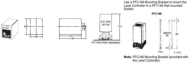
OMRON 61F-GPN-BT / -BC Dimensions
/Images/l_241-25-118527-198x198.jpglast update: December 19, 2013
• Outputs can be set to self-hold at ON or OFF using special circuits.
• Adjustable sensitivity, with an operating resistance range of 0 to 100 kΩ, allows use for a wide variety of liquids.
• Relay contact chattering conventionally caused by waves eliminated using open collector output, reducing contact wear.
• Meets CE marking and is a UL recognized component.
last update: December 19, 2013
Purchase the OMRON Floatless Level Controllers Please fill in the following
If you have just landed here, this product OMRON 61F-GPN-BT / -BC Switches,Switches is offered online by Tianin FLD Technical Co.,Ltd. This is an online store providing Switches at wholesale prices for consumers. You can call us or send enquiry, we would give you the prices, packing,deliverty and more detailed information on the 61F-GPN-BT / -BC We cooperate with DHL,TNT,FEDEX,UPS,EMS,etc.They guarantee to meet your needs in terms of time and money,even if you need your OMRON 61F-GPN-BT / -BCSwitches tomorrow morning (aka overnight or next day air) on your desk, 2, 3 days or more.Note to international customers, YES, we ship worldwide.
FQ2 Smart Camera/Features
FQ-M Series Vision Sensor/Features
G2R-[]-S (S) General-purpose Relay/Features
NX-ILM400 NX-series IO-Link Master Unit/Features
CJ1W-PA / PD CJ-series Power Supply Unit/Features
OMRON 61F-GPN-BT / -BC catalog
61F-GPN-BT / -BC Conductive Level Controller/Catalog- Catalog
- Manual
- CAD
English
Global Edition
| Catalog Name | Catalog Number [size] | Last Update | |
|---|---|---|---|
| | - [549KB] | Aug 06, 201520150806 | 61F-GPN-BT/GPN-BC Data Sheet |
| | N217-E1-01 [2428KB] | Jun 12, 201720170612 | Device Selection Guide for Water Level Control Applications |
OMRON 61F-GPN-BT / -BC lineup
61F-GPN-BT / -BC Conductive Level Controller/Lineuplast update: May 23, 2013
| Product name | Model number | |
|---|---|---|
| Conductive Level Controller | 61F-GPN-BT 24VDC | 61F-GPN-BC 24VDC |
| Open collector (NPN) | Relay contact (SPST-NO) | |
| Front Socket | PF113A-E | |
| Electrode Holder | (See note.) | |
Note: A variety of Holders are available to suit different types of application. For details, refer to 61F Floatless Level Controller (F030-E1).
last update: May 23, 2013
OMRON 61F-GPN-BT / -BC dimension
61F-GPN-BT / -BC Conductive Level Controller/Dimensionslast update: May 23, 2013
61F-GPN-BT/-BC

last update: May 23, 2013
OMRON 61F-GPN-BT / -BC specification
61F-GPN-BT / -BC Conductive Level Controller/Specificationslast update: August 06, 2015
Ratings
| 61F-GPN-BT | 61F-GPN-BC | |
|---|---|---|
| Rated voltage | 24 VDC | |
| Allowable voltage range | 85% to 110% of the rated voltage | |
| Interelectrode voltage | 5 VAC max. | |
| Operation resistance *1 | Variable (0 to 100 kΩ) | |
| Error | For scale of 0: +10 kΩ; For scale of 100: ±10 kΩ | |
| Release resistance | 200% max. of the operation resistance | |
| Switching between supply and drainage | Terminals 7 and 8 open: Automatic drainage operation Terminals 7 and 8 shorted: Automatic supply operation | |
| Output specifications | Open collector (NPN) 30 VDC, 100 mA max. Leak current: 100 μ A max. | Relay output, SPST-NO 5 A, 240 VAC (Resistive load) 5 A, 30 VDC |
| Life expectancy | --- | Electrical: 100,000 operations min. Mechanical: 20,000,000 operations min. |
| Accessories | Hold-down clip PFC-N8 | |
| Wiring distance *2 | 100 m max. | |
*1. The 61F may not operate at resistance settings close to zero. Adjust the sensitivity to match actual usage conditions.
*2. The figure for wiring distance above is for when 600-V 3-core cabtire cable with a cross-sectional area of 0.75 mm2
is used.
Characteristics
| Ambient operating temperature | -10 to 55°C |
|---|---|
| Ambient operating humidity | 25% to 85% |
| Insulation resistance | 100 MΩ min. (at 500 VDC) |
| Dielectric strength * | 2,000 VAC, 50/60 Hz for 1 minute |
| Power consumption | 2 W max. |
| Response time | Operating: 1.5 s max. Releasing: 3.0 s max. |
| Approved standards | UL61010-1, CAN/CSA C22.2 No.61010-1 EN61010-1 EN61326-1 Industrial electromagnetic environment |
* The dielectric strength is measured between power terminals and electrode terminals, power terminals and output
terminals, and between electrode terminals and output terminals.
last update: August 06, 2015
- NO. 61F-GPN-BT / -BC
- TYPE:Level Switches Floatless Level Controllers
 Copyright Statement
 - DATE:2021-06-13
- Associated products:
K8AK-LS Conductive Level Controller/Features 61F-G[]N Floatless Level Switch (Compact Type)/Features